Sharif University of Technology
Scientia IranicaTransactions D: Computer Science & Engineering and Electrical Engineering http://scientiairanica.sharif.edu
Designing an analog CMOS fuzzy logic controller for
the inverted pendulum with a novel triangular
membership function
S.M. Azimi
and H. Miar-Naimi
Department of Electrical and Computer Engineering, Babol Noshirvani University of Technology, Mazandaran, Iran. Received 20 September 2017; received in revised form 14 November 2017; accepted 3 March 2018
KEYWORDS Fuzzy logic; Fuzzy rules; Fuzzy controller; Fuzzy membership function;
PID controller; The inverted pendulum.
Abstract.This study provides a fuzzy analog controller circuit for the inverted pendulum problem that results in a simple analog circuit, which simply performs the act of controlling without requiring any processing structure. In other words, in the case of constructing the proposed circuit, a small analog chip controls the inverted pendulum. For this purpose, the rst step is to study the dynamic model of the inverted pendulum; then, a fuzzy controller is designed systematically. In the following, the number of Membership Functions (MFs) and their formation are designed. In addition, dierent MFs and numbers are examined for each variable, and the most ecient structure is selected as a fuzzy controller. To assess the eciency of the designed fuzzy controller, the controller is simulated in Simulink; then, this design is implemented at the transistor level by TSMC 0.18 m CMOS technology. In this work, the MFs and the circuits for realization of the knowledge-based and defuzzication circuits are designed in the current mode. The proposed circuits are simulated and evaluated by Advanced Design System (ADS) software based on CMOS technology. Simulation results show that the inverted pendulum is controlled with high accuracy and high speed; meanwhile, controllers have low power consumption and good robustness to handle outer large and fast disturbance, as compared to the previous works. © 2019 Sharif University of Technology. All rights reserved.
1. Introduction
The implementation of systems in analog [1] and inte-grated circuits leads to a reduction in area, a decrease in power, and simplicity of the circuit function. Using a fuzzy controller is one of the most eective ways to control complex, unstable and nonlinear systems [2-5] without a processor, while other methods generally tend to have a processing system for implementation. One of the important issues concerning the evaluation
*. Corresponding author.
E-mail addresses: [email protected] (S.M. Azimi); h [email protected] (H. Miar-Naimi)
doi: 10.24200/sci.2018.5224.1153
of control systems is the inverted pendulum control problem or rotary inverted pendulum [6]. The control technology derived from the inverted pendulum is ap-plied to many industrial and engineering products such as high-precision control of a manipulator, stabilization and tracking control of launching rocket, and attitude control of satellite [7]. Some studies have been done to implement fuzzy controllers to solve this problem [8-12]. These circuits are usually a combination of analog and digital circuits [13-15] or digital [16]. Of note, analog implementation has not been carried out completely yet. Figure 1 shows an inverted pendulum system.
The inverted pendulum is dened as a rod lo-cated on the chariot that moves horizontally. The inverted pendulum is inherently unstable in the upright
Figure 1. The inverted pendulum.
Table 1. The inverted pendulum-chariot system parameters.
Mc (kg) Mass of chariot Mp (kg) Mass of pendulum b (N/m/sec) Friction coecient
L (m) Length between axle center and the center of pendulum Inertia (kg:m2) Inertia of pendulum
g (m/s2) Gravity acceleration
F (N) Applied force X (m) Chariot position
(radian) Angle deviation of pendulum
position and requires a controller in order to keep it moving vertically. The inverted pendulum is a classic problem in dynamics and control theory and is used as a benchmark for testing control strategies. The inverted pendulum, as shown in Figure 1, is aected by an impulse force, F . This condition is essential to controlling the pendulum vertically.
As can be seen in Figure 1, the system includes a rod with the mass of Mp and the length of l located on a chariot with the mass of Mc aected by force F and can move along the horizontal axis; thus, the pendulum is diverted from the vertical condition. The purpose of controlling this system is to balance the pendulum (i.e., = 0). For a more precise denition of the mechanical system of the inverted pendulum, parameters of this system are dened in Table 1.
Fuzzy controller methods are particularly one of the most impressive and convenient ways to con-trol nonlinear systems. Many references show that fuzzy controllers operate more eciently than standard controllers do [8-12]. For this reason, this research attempts to design a fuzzy controller for the inverted pendulum problem and is implemented as an analog circuit. As noted above, some studies have been conducted to design a fuzzy control system and other controlling strategies to control the inverted pendulum. In this section, a few of them will be noted.
In [8], two methods of the PID conventional
controller and the rule-based fuzzy logic controller were designed and compared. The proposed fuzzy circuit in [8] had two controllers that were used for chariot position control and pendulum control. Eventually, the results of these two forces and disturbance force were applied to the inverted pendulum to control it. In [8], Ziegler-Nichols criteria were used to tune the control parameters of the PID controller. According to the simulations done in [8], it can be concluded that fuzzy logic control works more eectively than the PID control. These results are achieved in Matlab.
In [9], basic performances of Fuzzy Logic Control (FLC) and conventional PID control were contrasted. According to paper [9], the fuzzy control had smaller overshoot and shorter settling time; hence, the su-periority of fuzzy control received much attention. In addition, according to the results of the study, compared with the modern control theory, the fuzzy logic is easier to implement because it eliminates the complexities of the process of mathematical modeling; instead, a set of control rules is used. Fuzzy control, in comparison with PID control, is more robust against parameter changes. In addition, fuzzy logic is not based on the mathematical model of the inverted pendulum and is more robust to mass variations. The weakness of the proposed fuzzy controller in [9] lies in the complexity of the used fuzzy rules; however, it is not easy to modify or change specications. The proposed work attempts to have a simple structure of fuzzy rules that can be reset for other characteristics easily.
In [10], according to Single Input Rule Modules (SIRMs), a fuzzy controller was used to stabilize an inverted pendulum. The intended fuzzy controller has a high ability to stabilize a wide range of inverted pendulum systems [10]. In this procedure, angular control of the pendulum and the chariot control can be done in parallel, and both of them, according to control situations, are switched smoothly by adjusting the dy-namic importance degrees automatically. In [10], large deviations occurred; then, the system was controlled.
Another architecture of a fuzzy controller for the inverted pendulum was studied [11]. Facility and understandable fuzzy rules are the advantages of the intended design; however, the circuit consists of A/D blocks, D/A blocks, a power amplier, and a servomotor, while using analog design eliminates these blocks. This control technique relies on the human capacity to understand the system's behavior and is based on qualitative control rules. The authors in [11] showed that fuzzy control systems were more robust to variations of parameters (mass and length of the pendulum) than conventional PID control systems.
In [12], an 8-bit microprocessor, according to fuzzy control for the rotary inverted pendulum, was presented. The hardware of the system includes a user interface, a control circuit box, and a rotary
inverted pendulum system. The fuzzy controller consists of two microprocessors: the master one for fuzzy logic operation and the slave one for user [12]. This circuit is composed of an optical encoder for angle and location detection, counters, a keyboard, two microprocessors, a clock, programmable peripheral interface, a transceiver, a DC motor, etc. The proposed design [12] is highly complex because of using dierent components, analog, and digital parts.
In [17], PID controllers were applied to stabi-lization and tracking control of three types of an inverted pendulum system. When a control system has more than two PID controllers, the adjustment of PID parameters is not an easy problem. The authors in [17] presented a new way to design very simple and eective PID controllers.
Unfortunately, the mentioned papers outlined above did not evaluate the performance of the proposed controller accurately and quantitatively and were not compared with other works. Thus, they could not achieve the appropriate conclusion of this research [8-12,17]. Perhaps, one reason for the failure to solve this problem lies in the multifacetedness of the desired control issue. To sum up in brief, in all of the last works, the controllers have been applied to the pro-cessing systems, demonstrating hardware complication, instead. However, in this paper, the controller is completely applied to the analog chip. The proposed work is an attempt to design fuzzy rules to control the system fast enough. This particular example may be of purely scientic value; however, the proposed approach in the design and the implementation of analog chips can be the basis of designing larger and more practical control systems. Unlike previous works, in the present study, some indicators, such as robustness, power consumption, controlling range of disturbance, and maximum deviation, are considered to evaluate the performance of controllers.
The rest of the paper is organized as follows: the second section is dedicated to a brief review of fuzzy logic and fuzzy controllers. In the third section, the fuzzy control system design is expressed, and system-atical simulation results are discussed. In the fourth section, the implementation of the intended controller is presented as an analog chip. In the fth section, ADS simulation results are presented and compared with Matlab simulations. In the sixth section, some conclusions are stated.
2. Brief review of fuzzy logic and fuzzy controllers
2.1. Fuzzy logic
One of the advantages of fuzzy controllers is that the designer does not need to know the exact dynamic model. Hence, fuzzy controllers can be designed only
based on system behavior so that they can control the intended system. Lot A. Zadeh proposed that \as the complexity of the system increases, the possibility of describing the system with deterministic terms diminishes" [18]. In the following, the fuzzy logic and fuzzy controller will be expressed briey. One of the most important characteristics of fuzzy logic is the use of linguistic variables, instead of numerical variables. Linguistic variables are dened as variables in a natural language such as small/large, almost/certainly, etc. Fuzzy sets are not similar to classic sets to which a member belongs or not. Fuzzy sets allow partial membership in a set, which means that an element belongs to more than one set [19]. Each fuzzy set is characterized by its MF whose member is allocated a number between zero and one. Based on these MFs, logical operations were redened among sets.
2.2. Fuzzy logic controller
Fuzzy systems are knowledge-based systems. The heart of a fuzzy system is a knowledge base that consists of if-then rules. The if-then rule is an expression based on which some words have been specied with continuous MFs. According to some of the fuzzy rules, applications can be used for fuzzy controllers, fuzzy expert systems, fuzzy approximate arguments, pattern recognition, and fuzzy decision. In daily life, the if-then statements are used frequently.
The computational complexity of fuzzy rules is expressed by several parameters: the number of inputs, the number of outputs, the number and shape of the MF I/O, the number of rules, method of rules inference, defuzzication algorithm, and accuracy. Typically, a fuzzy controller is composed of a set of if-then rules involving three following basic operations (Figure 2):
(a) Fuzzication: It is an operation that translates crisp input data into a membership degree by means of the MFs;
(b) Fuzzy inference: This operation uses the mem-bership degrees to deduce a fuzzy output for each rule and a nal fuzzy output of the controller;
(c) Defuzzication: It is an operation that
lates the nal fuzzy output into a crisp value compatible with the deterministic external envi-ronment [8].
3. Fuzzy control system design and system simulation results
It is practically impossible to control the inverted pendulum because of extreme nonlinear behavior with the linear conventional control method, or is applicable in very small ranges. This system is actually of one-input and two-output type. The position of the chariot and the angle of the pendulum simultaneously will be under control with a control signal.
3.1. Inverted pendulum modeling
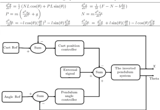
By writing dynamic equations of chariot and pendu-lum, categories of the equations are obtained. Indeed, these equations are the dynamic model of the system. Equations of the dynamics of the pendulum and the chariot can be described in dierent ways [8,20,21]. A summary of the equations concerning the system is shown in Table 2 [8].
Variable N is an interaction force of pendulum and chariot along x-axis, and P is an interaction force of these two along y-axis. The rest of the variables are shown in Table 1.
3.2. The design of the fuzzy controller for the inverted pendulum
A general exponent of a chariot position and angle deviation of the pendulum controller is shown in Figure 3.
In this design, the inverted pendulum has been controlled with two controllers [8]: angular controller and position controller. Each controller has two input variables. The pendulum angle error and its derivative have been used in the pendulum angular controller. The position controller uses the position error and its derivative. Due to the dynamic equations of this system, there are two dynamic objects in the inverted pendulum-chariot system: the pendulum and the chariot. The rule-base mechanism of the controller for separately controlling the pendulum and chariot is easier to implement. However, there is only one control action to control the inverted pendulum-chariot system. Thus, control force F p for the pendulum subsystem and control force F c for chariot subsystem require to be combined into a control force.
It can be seen that driving the chariot to the left side causes the pendulum to go to the right. The goals of the inverted pendulum control system are to balance the pendulum in the vertical situation and to x the chariot in the reference point. A combination of F p and F c is force F = F p F c. In this study, all six universes of discourse are divided into ve overlapping fuzzy set values labeled as Negative Big (NB), Negative Medium (NM), Zero (Z), Positive Medium (PM), and Positive Big (PB). The fuzzication in a fuzzy set is determined by dierent types of MFs such as trapezoidal, triangu-lar, z-shape, s-shape, Gaussian-shape [22-26], and bell-shaped MFs. The shapes of MFs of less signicance to the fuzzy inference system, and the number and the extent of changes in MFs are more important. Simplicity in design and desired precision are good
Table 2. Describing equations of the inverted pendulum.
d2
dt2 = 1I(NL cos() + P L sin()) d 2x
dt2 = M1 (F N bdxdt) P = m
d2yp
dt2 + g
N = md2xp
dt2
d2yp
dt2 = l cos()(ddt)2 l sin()d 2
dt2 d 2xp
dt2 = d 2x
dt2 + l sin()(ddt) l cos()d 2
dt2
reasons to use triangular MFs in this work. Mamdani's technique is one of the most commonly used inference strategies in the existing fuzzy control systems owing to its simplicity. In this method, the minimum operation is adopted to compute the fuzzy implication relation and the max-min as the compositional rule of [27]. The proposed fuzzy controller is used in this procedure. The output of a fuzzy inference engine is a fuzzy set, which represents the possible distribution of control action. For practical usage, a crisp control output is usually required. Thus, a defuzzication interface is necessary to convert the inferred fuzzy control action to a non-fuzzy (crisp) value. Among the suggested defuzzication strategies, the Center Of Area (COA) method is the most commonly used one [13].
3.3. Fuzzy control rules
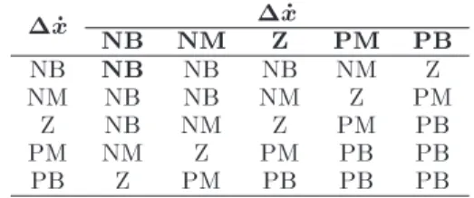
The rule base is constructed using the if-then state-ments. The most dicult aspect of designing fuzzy controllers is the design and construction of a rule base. The rule base mechanism is more convenient to design for separate control of the pendulum and the chariot. Rule design is based on innovative knowledge of the behavior of the system and its theory. In addition, a designer uses his experience and trial-and-error approach to discover the best system rule base. For example, in this application, if the pendulum is falling in one direction, then the inverse movement of the pendulum occurs by pushing the chariot in the same direction. For example, to control the chariot, rules can be changed at will. In this analysis, displacement x is the dierence between the starting location and the current chariot position. Therefore, when the chariot shifts toward the positive position, displacement is negative; in the negative position, displacement is positive. If displacement and the pace of change are negatively large, the chariot is on the positive part of the axis and moves away from the starting location. In this case, a negatively large force should be applied to control the chariot so that it can return to its starting location. This descriptive rule is expressed with a gray background in Table 3. Likewise, the rest of the rules can be described. The fuzzy rules can be seen in Table 3.
The fuzzy rule base is completed, and the next step concerns the implementation of the controller based on the knowledge base. First, fuzzy variables must be described. In other words, each MF should
Table 3. Chariot position fuzzy control rules.
_x NB NM _xZ PM PB
NB NB NB NB NM Z
NM NB NB NM Z PM
Z NB NM Z PM PB
PM NM Z PM PB PB
PB Z PM PB PB PB
Figure 4. MFs of: (a) Chariot position (x) and (b) its derivative ( _x).
Figure 5. Force membership functions.
be dened. Choosing the details of MFs depends on behavior recognition and design knowledge. In this example, MFs are designed in a relatively small range to control the conducted action more appropriately. In this study, it is assumed that the system is fully controlled, and the chariot cannot get away from the starting location in practice. Therefore, under perturbation, if the system is out of the control, the chariot position will undergo small changes around its equilibrium point. MFs of chariot position (x) and its derivative ( _x) are shown in Figure 4.
Figure 6. Diagram of position controller (for F = NB): (a) Fuzzication, (b) fuzzy inference, and (c) defuzzication.
membership degree should be obtained for any possible states to implement the controller in each mode of force. To investigate the possibility of NB force for the position controller, the following system diagram is used (Figure 6). The pendulum angular controller is designed in a similar way. The triangular MFs of and _ are dened as follows: [-0.1,0.1] and _ [-0.2,0.2]. Figure 7 shows MFs of and _.
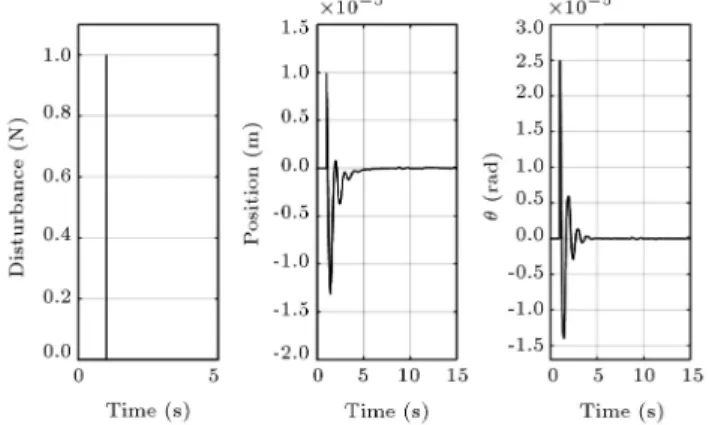
The inverted pendulum specications include mc = 0:5 kg, mp = 0:2 kg, l = 0:3 m, b = 0:1 N/m/sec, inertia = 0.006 kg.m2, and g = 9:8 m/s2. Various
disturbances are applied in MATLAB software, and the controller operation is analyzed. If the input with 1 N amplitude in a short period of time is applied to the inverted pendulum-chariot system, the chariot and the angle of the pendulum must be controlled in four
seconds (see Figure 8). The input actions ranging from two to ve seconds with the amount of 1 N will produce output, as shown in Figure 9.
4. Implementation of the proposed controller for analog chip
To appraise the performance of the designed fuzzy controller in ADS, the inverted pendulum model is implemented. An inverted pendulum model includes op-amp circuits, resistors, capacitors, and math blocks (e.g., SDD blocks are used to implement mathematical operations). First, it is necessary for MFs to be designed as analog circuits to implement the analog de-signed controller. The minimum (Min) and maximum (Max) circuits are used to fulll MFs.
Figure 7. Membership functions of (a) pendulum angle () and (b) its derivative ( _).
Figure 8. First system response.
Figure 9. Second system response.
4.1. Min-max circuits
According to the application of min and max circuits, diverse circuits are designed in current and voltage modes [28-32]. The circuits may perform in dierent ways. One of these methods uses equations to acquire minimum or maximum current [31]. A current-current MFG was presented in [31] to display the min and max circuit performance. By comparing it with other MFG circuits in the current mode, input and output ranges of this MFG circuit are quite wide, and each side slope can independently vary to achieve a triangular or trapezoidal MFG. Another large part of the circuits is designed based on current mirrors [28].
In [28], the minimum and maximum currents are obtained simultaneously; however, in this study, the modied circuits are used (Figure 10). In this case, the number of min and max circuit transistors will be eight and twelve transistors, respectively.
Considering that the controller design is in the current mode, it is preferred that the input impedance of the circuits be small. Therefore, the proposed min-max circuits have been selected on this basis. It is explicit that with an increasing aspect ratio or increasing DC current bias, the input impedance is improved at a cost of sacricing the die chip area and the circuit's speed; in addition, output impedance is large enough to transfer all of the output currents to the load. To ameliorate the output impedance circuit, the DC bias current should be diminished [28].
Suppose that I1 > I2 for min circuit; thus,
the voltage at node A increases more than node B. Accordingly, M8 turns on and M7 turns o. Then, current I2is transferred to the current mirror, and the
dierence between these two currents passes through M8; however, to achieve the maximum current, this dierence current should be transferred to other cur-rent mirrors and be added to the minimum curcur-rent to create the maximum current.
4.2. Novel MF generator
One method for implementing triangular and trape-zoidal MFs was presented in [31]. Accordingly, an MF was made with three min circuits that occupy a high area. The proposed MFG circuit (Figure 11) is presented in this paper which uses only one min circuit so that the size and power consumption decrease considerably. In the proposed triangular MF, a and c are the minimum and maximum input currents, respectively (Figure 12). The highest membership degree is Imaxthat occurs when the input current is b.
The input current is compared with the lowest current and maximum current. If Iin < a and Iin > c, the
output current value will be zero, otherwise will have two currents according to the left and right slopes of the triangle. Then, these two currents are compared,
Figure 10. (a) Min circuit. (b) Max circuit.
Figure 11. Novel MFG block.
Figure 12. Triangular MF.
and the lowest value of these two currents will be the output current.
The inverted pendulum-chariot controller system, which uses the proposed MF, has 480 transistors, which is less than what the previous MF structure
has. Therefore, the occupied area of the controller is reduced signicantly. In addition, power consumption is improved, as compared to the status of the prior circuits.
MFs applied to an analog circuit are based on cur-rent. Currents are values about a few tens or hundreds of microamperes in 0.18 m technology. MFs in the analog circuit have been rewritten (from Matlab values in Figures 4 and 6), as shown in Figures 13 and 14. In other words, real variables, such as position and angle in centimeter and radian scale, become current times of microseconds. Therefore, the used MFs are as follows. 5. ADS simulation results
In this section, the force of 1 N on the brief moment (0.001 s) (Figure 15(a)) is applied to an inverted pendulum. The pendulum will be also unstable and chariot displaces from the reference location; after a few seconds, both of them will return to the reference situation (Figure 15(b), and (c)). In the next exami-nation, disturbance force is 1 N step for three seconds (Figure 16(a)). The controller performs the desired control action (Figure 16(b), and (c)).
Figure 14. (a) Analog implementation of pendulum angle () MF. (b) Analog implementation of ( _) MF.
Figure 15. System behavior: (a) Disturbance input, (b) angle, and (c) position.
Figure 16. System behavior: (a) Disturbance input, (b) angle, and (c) position.
According to a comparison done between system-atical simulation results (Figures 8 and 9) and analog design results (Figures 15 and 16), both behaviors were properly similar. There are minor dierences in overshoot and settling time due to the use of non-ideal circuit components (capacitors, transistors, etc.); the dierences are not unexpected.
5.1. Controlling range of disturbance
Regarding the controlling ranges, when the disturbance force, which is equal to 34 N in 0.001 s, is applied to the inverted pendulum-chariot system, the system is controlled (Figure 17). In addition, if greater force is applied to the system, the controller cannot control it (Figure 18 shows results with force = 35 N). In addition, it can be seen that the system controls negative disturbance force until -35 N (Figure 19), and
the controller cannot control disturbance force lower than -36 N (Figure 20). As a result, the control-ling ranges for the given xed specications of the inverted pendulum system are [-35,34] N. This design can be used to control a wide range of perturbations forces.
5.2. Robustness
Robustness is one of the parameters that concerns control systems. The parameters that dene the inverted pendulum is considered xed, and changes in the mass of the pendulum and cart is investigated. The results of this system are summarized in Table 4.
In the previous sections, this factor was con-sidered as one of the important control assays. By analyzing the system, the robustness of the proposed controller was shown.
Figure 17. System response to F = 34 N: (a) Angle, and (b) position.
Figure 18. System response to F = 35 N: (a) Angle, and (b) position.
Figure 19. System response to F = 35 N: (a) Angle, and (b) position.
Figure 20. System response to F = 36 N: (a) Angle, and (b) position.
5.3. Comparison of the designed fuzzy system and PID control system
The inverted pendulum is characterized by mc = 0.5 (Kg), mp = 0.2 (kg), l = 0.3 (m), b = 0.1 (N/m/sec), inertia = 0.006 (kg.m2), and g = 9:8 (m/s2); PID
control parameters are also shown in Table 5. The results of comparing these two control methods for turbulence with the same specications of the inverted pendulum are presented in Tables 6 and 7. As shown in Tables 6 and 7, the proposed fuzzy controller is more
Table 4. The stability investigation of the inverted pendulum system for changes in mass. Constant parameters
The extent of changes in the mass of the system is controlled
with the desired speed Mp = 0:2 kg, L = 0:3 m (0:1 Mc 3:5) kg Mc = 0:5 kg, L = 0:3 m (0:1 Mp 8) kg
Table 5. PID control parameters. Gain For pendulum angle
controller
For cart position controller
KP 41 2
KI 38 0.02
KD 27 0.4
Table 6. The evaluation of fuzzy control and PID control methods with 0.001 N amplitude of impulse input. Maximum deviation of
cart position
Maximum deviation of pendulum angle
The proposed fuzzy method -70 nmm 50 n rad
PID control 0.6 mm 30 rad
Table 7. The evaluation of fuzzy control and PID control methods with 1N amplitude of impulse input. Maximum deviation of
cart position
Maximum deviation of pendulum angle
The proposed fuzzy method 19 m 48 rad
PID control 0.6 m 0.03 rad
Table 8. The comparison of the proposed FLC chip with those in previous recent works.
References Technology (m) Shape type Supply voltage (V) Power (mW)
[13] 0.35 Trapezoidal, Gaussian, Triangular | 13.4
[15] 0.35 Trapezoidal, Triangular | 10.49
[16] 0.35 Trapezoidal, Triangular | 49
[33] 0.35 Trapezoidal, Triangular 3.3 8
[34] 1.2 Trapezoidal, Triangular 2.5 16.3
[35] 0.35 Trapezoidal, Gaussian 3.3 2.5
Proposed 0.18 Triangular 1.8 0.0234
eective and has lower deviation. 6. Conclusions
One of the most important issues of control is the inverted pendulum control. In this paper, an analog fuzzy controller as an ecient control method was implemented to control the inverted pendulum. Using this method leads to removing processing systems, the digital circuits, converters, and other equipment. Analog chips with a very small area and high speed without any external processor can control a wide range of disturbances. The architectures have been designed and implemented in a TSMC 0.18 m CMOS
technology with a 1.8 V supply voltage. According to the simulation results, the average current of the controller is 13 A. As a result, the power consumption of each chip is 23.4 W. The main characteristics of the intended fuzzy controller are summarized as follows:
Simple circuitry;
High-speed controlling;
Low die area;
Controlling a wide range of disturbances;
Lower power consumption than other circuits. Ta-ble 8 compares the proposed FLC with other works.
The advantages of the proposed triangular MF include simple structure, lower power consumption, small area, and high-precision performance as compared to that of previous works.
References
1. Dualibe, C., Verleysen, M., and Jespers, P.G.A., De-sign of Analog Fuzzy Logic Controllers in Cmos Tech-nologies, Kluwer Academic Publishers, The United States of America (2003).
2. Yu, J., Shi, P., Dong, W., and Lin, C. \Command ltering-based fuzzy control for nonlinear systems with saturation input", IEEE Trans. Cybern, 47(9), pp. 2472-2479 (2017).
3. Mehrpooya, M. and Hejazi, S. \Design and imple-mentation of optimized fuzzy logic controller for a nonlinear dynamic industrial plant using Hysys and Matlab simulation packages", Ind. Eng. Chem. Res, 54(44), pp. 11097-11105 (2015).
4. Jafari, R. and Yu, W. \Fuzzy control for uncertainty nonlinear systems with dual fuzzy equations", J. Intell. Fuzzy Syst., 29(3), pp. 1229-1240 (Oct. 2015).
5. Li, L. and Sun, Y. \Adaptive fuzzy control for nonlinear fractional-order uncertain systems with un-known uncertainties and external disturbance", En-tropy, 17(8), pp. 5580-5592 (Aug. 2015).
6. Sirisha, V. and A. Junghare, S. \A Comparative study of controllers for stabilizing a rotary inverted pendulum", Int. J. Chaos, Control. Model. Simul., 3(1/2), pp. 113 (Jun. 2014).
7. Jia-Jun, W. \Position and speed tracking control of inverted pendulum based on double PID controllers", In 2015 34th Chinese Control Conference (CCC), pp. 4197-4201 (2015).
8. Akole, M. and Tyagi, B. \Design of fuzzy logic con-troller for nonlinear model of inverted pendulum-cart system", XXXII Natl. Syst. Conf. NSC, pp. 750-755 (2008).
9. Nour, M.I.H., Ooi, J., and Chan, K.Y. \Fuzzy logic control vs. conventional PID control of an inverted pendulum robot", 2007 Int. Conf. Intell. Adv. Syst., pp. 1-6 (2007).
10. Yi, J. and Yubazaki, N. \Stabilization fuzzy control of inverted pendulum systems", Artif. Intell. Eng., 14(2), pp. 153-163 (Apr. 2000).
11. Chen Wei Ji, Fang Lei, and Lei Kam Kin \Fuzzy logic controller for an inverted pendulum system", In 1997 IEEE International Conference on Intelligent Processing Systems, pp. 185-189 (1997).
12. Chih Hui Chiu and Wei Yu Chen \A chip based fuzzy logic controller", In IEEE International Conference Mechatronics and Automation, 4, pp. 2194-2199 (July 2005).
13. Yose, G., Aminifar, S., Neda, S., and Daneshwar, M.A. \Design of a mixed-signal digital CMOS fuzzy
logic controller (FLC) chip using new current mode circuits", AEU - Int. J. Electron. Commun., 65(3), pp. 173-181 (2011).
14. Orcioni, S., Biagetti, G., and Conti, M. \A Mixed signal fuzzy controller using current mode circuits", Analog Integrated Circuits and Signal Processing., 38, pp. 215-231 (2004).
15. Amirkhanzadeh, R., Khoei, A., and Hadidi, K. \A mixed-signal current-mode fuzzy logic controller", AEU - Int. J. Electron. Commun., 59(3), pp. 177-184 (2005).
16. Aminifar, S., Khoei, A., Haidi, K., and Yose, G. \A digital CMOS fuzzy logic controller chip using new fuzzier and max circuit", AEU - Int. J. Electron. Commun., 60(8), pp. 557-566 (2006).
17. Wang, J.J. \Simulation studies of inverted pendulum based on PID controllers", Simul. Model. Pract. The-ory, 19(1), pp. 440-449 (2011).
18. Yamakawa, T. \Electronic circuits dedicated to fuzzy logic controller", Sci. Iran., 18(3D), pp. 528-538 (2011).
19. Wang, L.-X., A Course in Fuzzy Systems and Control, Prentice-Hall International, Inc (1997).
20. Mobara, M., Karimpour, A., MollaAhamadian, H., and Pahnabi, A. \Modeling and control of inverted pendulum based on PWA-FUZZY approach", In 2015 International Congress on Technology, Communica-tion and Knowledge (ICTCK), pp. 112-116 (2015).
21. Becerikli, Y. and Celik, B.K. \Fuzzy control of in-verted pendulum and concept of stability using Java application", Math. Comput. Model, 46(1-2), pp. 24-37 (2007).
22. Daneshvar, M. \Programmable trapezoidal and Gaus-sian membership function generator", Basic Appl. Sci. Res., 1(11), pp. 2073-2079 (2011).
23. Moshfe, S., Khoei, A., Hadidi, K., and Mashou, B. \A fully programmable nano-watt analogue CMOS circuit for Gaussian functions", In 2010 International Confer-ence on Electronic Devices, Systems and Applications, pp. 82-87 (2010).
24. Esmaeil Pour, M. and Mashou, B. \A low power con-sumption and compact mixed-signal Gaussian mem-bership function circuit for neural/fuzzy hardware", In 2011 International Conference on Electronic Devices, Systems and Applications (ICEDSA), pp. 87-91 (2011).
25. Khaneshan, T.M., Nematzadeh, M., Khoei, A., and Hadidi, K. \An analog recongurable Gaussian-shaped membership function generator using current-mode techniques", ICEE 2012 - 20th Iran. Conf. Electr. Eng., pp. 145-149 (2012).
26. Chih-Min Lin and Hsin-Yi Li \Adaptive dynamic sliding-mode fuzzy CMAC for voice coil motor using asymmetric Gaussian membership Function", IEEE Trans. Ind. Electron., 17(8), pp. 5662-5671 (Oct. 2014).
27. Pandiyan, M. and Mani, G. \Embedded low power analog CMOS fuzzy logic controller chip for industrial applications", In 2015 IFIP/IEEE International Con-ference on Very Large Scale Integration (VLSI-SoC), pp. 43-48 (2015).
28. Alikhani, A. and Ahmadi, A. \A novel current-mode min-max circuit", Analog Integr. Circuits Signal Pro-cess., 72(2), pp. 343-350 (2012).
29. Ranjbar, M., Karimi, G., and Razaghian, F. \A novel low voltage CMOS controllable fuzzy inference circuit", Analog Integr. Circuits Signal Process., 84(2), pp. 149-160 (2015).
30. Prommee, P., Angkeaw, K., Somdunyakanok, M., and Dejhan, K. \CMOS-based near zero-oset multiple inputs max-min circuits and its applications", Analog Integr. Circuits Signal Process., 61(1), pp. 93-105 (2009).
31. Mesgarzadeh, B. \A CMOS implementation of current-mode min-max circuits and a sample fuzzy appli-cation", In IEEE International Conference on Fuzzy Systems, pp. 941-946 (2004).
32. Prommee, P. and Chattrakun, K. \CMOS WTA max-imum and minmax-imum circuits with their applications to analog switch and rectiers", Microelectronics J., 42(1), pp. 52-62 (2011).
33. Peymanfar, A., Khoei, A., and Hadidi, K. \Design of a general propose neuro-fuzzy controller by using mod-ied adaptive-network-based fuzzy inference system", AEU - Int. J. Electron. Commun., 64(5), pp. 433-442 (2010).
34. Peyravi, H., Khoei, A., and Hadidi, K. \Design of an analog CMOS fuzzy logic controller chip", Fuzzy Sets Syst., 132(2), pp. 245-260 (Dec. 2002).
35. Soleimani, M., Khoei, A., and Hadidi, K. \Current-mode analog CMOS fuzzy logic controller", In 2010 IEEE Asia Pacic Conference on Circuits and Sys-tems, 1, pp. 224-227 (2010).
Biographies
Seyed Milad Azimi was born in Sari, Iran in 1992. He received the BSc and MSc degrees in Electrical Engineering from Babol Noshirvani University of Tech-nology, Babol, Iran in 2014 and 2017, respectively. In 2014, he joined the Integrated Circuit Research Laboratory, Department of Electrical and Computer Engineering, Babol Noshirvani University of Technol-ogy, as a Researcher. His current research interests include CMOS integrated circuits for fuzzy controllers and Flip-op design in nanometer CMOS from high speed to low energy.
Hossein Miar Naimi was born in Chalous, Iran in 1972. He received the BSc degree from Sharif University of Technology, Tehran, Iran in 1994, the MSc degree from Tarbiat Modares University, Tehran in 1996, and the PhD degree from Iran University of Science and Technology, Tehran in 2002, all in Electrical Engineering. Since 2003, he has been a member of the Electrical and Electronics Engineering Faculty, Babol University of Technology where he became a Professor in 2014. His research interests are analog CMOS integrated circuit design, RF and microwave microelectronics.