Karona Apsara Tum
A thesis submitted to the faculty at the University of North Carolina at Chapel Hill in partial fulfillment of the requirements for the degree of Master of Science in the School of Dentistry
(Prosthodontics).
Chapel Hill 2016
DETERMINATION of OCCLUSAL PLANE USING BONY ANATOMICAL LANDMARKS THROUGH THE ANALYSIS of CONE BEAM COMPUTED
TOMOGRAPHY
Approved by:
Glenn E. Minsley
Donald A. Tyndall
ABSTRACT
Statement of problem: Establishing the occlusal plane of the edentulous mouth is challenging but with the accuracy of 3D radiography, the orientation of the occlusal plane can be determined using stable anatomical landmarks.
Purpose: The purpose of this study was to determine the location of the occlusal plane in relation to stable, bony anatomical structures.
Material and Methods: Stable bony structures were identified and the orientation of the occlusal plane was determined in relation to these landmarks, using CBCT scans.
Results: The anterior determinant of occlusal plane is located 29mm (95% CI: 28.3mm to 30.0mm) inferior to the anterior nasal spine (ANS). In relation to the hamular notch-incisal edge (HNI) plane, the occlusal plane forms a 15.5o angle (95% CI: 14.7o to 16.2o).
Conclusions: Results from this study will enable dentists and technicians to accurately locate the occlusal plane in a virtual environment without the use of an analog face-bow.
Karona Apsara Tum: Determination of Occlusal Plane Using Bony Anatomical Landmarks Through the Analysis of Cone Beam Computed Tomography
To my family: I could not have accomplished all of this without you. I am grateful for the sacrifices you have made in helping me realize my dream.
TABLE OF CONTENTS
LIST OF TABLES ... vii
LIST OF FIGURES ... viii
CHAPTER 1. INTRODUCTION ... 1
1.1. Invention of the face-bow ... 1
1.2. Location of arbitrary vs. actual hinge axis ... 2
1.3. Effects of using arbitrary hinge axis on fixed dental restorations ... 4
1.4. Advantages and disadvantages of the face-bow ... 5
1.5. Is it crucial to use a face-bow in denture fabrication? ... 6
1.6. Comparison of traditional (T) vs. simplified (S) denture fabrication technique ... 7
1.7. Incorporation of technological advancement in denture fabrication ... 8
2. MATERIAL and METHODS ... 11
3. RESULTS ... 14
6. CONCLUSION ... 22
LIST OF TABLES
Table 1: List of inclusion and exclusiuon criteria ... 15
Table 2: Anatomical structures and dental landmarks ... 15
Table 3: Mean distances and angulations between landmarks and
LIST OF FIGURES
Figure 1: Simplant Orthodontics and Orthognathics software ... 16
Figure 2: Distance between anatomical and dental landmarks ... 17
Figure 3: Angulation between HNI and occlusal planes ... 18
INTRODUCTION
Smile is a universal welcoming sign and expression of happiness. Due to aging
process and broken dentition, the smile may be severely compromised. In order to
re-establish the proper location of teeth in edentulous mouth, the location of incisal edge and
natural occlusal plane must be determined. The proper orientation of maxillary cast in an
articulator facilitates the establishment of the occlusal plane. This step is traditionally
accomplished by using a face-bow transfer. Since its introduction in 1899, the advantages
and disadvantages of the face-bow in prosthodontic rehabilitation have been thoroughly
discussed, however, the relationship between the face-bow hinge axis and the true hinge axis
as well as the clinical value of hinge axis determination has been questioned and
inconclusively discussed.
1.1. Invention of the face-bow
A face-bow transfer records and preserves the relationship of the maxillae to condylar
hinge axis. Although, Bonwill, Hayes, Walker and Balkwill recognized the importance of
maintaining the relationship of the maxillae to the condylar hinge axis, it was Gysi’s and
Snow’s invention that were able to replicate this relationship. Gysi’s face-bow was “capable
of obtaining more than one position relation record” (1), making it a combination of tracing
device and face-bow, however “it lacked the simplicity of Snow’s unifunction face-bow”. In
All prototypes of face-bows in use today are based on Snow’s face-bow design (2).
There are two types of face-bows available, arbitrary face-bow and kinematic or hinge-bow.
The use of kinematic face-bow “is capable of determining the rotational center of the hinge
axis of the condyles” (1). “The area of the true hinge axis was located by palpating the
subject’s condyles during opening and closing of the mandible” (2). While it is important to
accurately capture the relationship of the maxillae to the condylar hinge axis and transfer that
relationship to a semi-adjustable articulator, the use of such face-bow is not of a practical
one. Using a kinematic face-bow is a lengthy and difficult procedure and requires greater
initial investment. Although the kinematic face-bow is used to actually locate the hinge axis,
the arbitrary face-bow technique is considerably less time-consuming and sufficiently
accurate for routine procedures (2).
1.2. Location of arbitrary vs. actual hinge axis
Beyron (3) in 1942 compared the relationship of arbitrary hinge axis to the true hinge
axis and determined that only 10 out of 39 study subjects have normal occlusion.
Schallhorn’s study (1) selected 70 dental students with normal occlusion and full
complement of at least 28 teeth to determine the location of true hinge axis in relation to the
arbitrary hinge axis. All recordings were made to opening of 10mm, a pure hinge-axis. It
was reported by McCullom (4) and confirmed by Eberle (5) that the mouth may be opened at
least one-half inch on a purely hinge basis. According to Shallhorn 95% of the true hinge
axis locations fall within 5mm radius of an arbitrary axis (1). The results from his study
“1. The arbitrary axis of rotation as set forth by Snow, Gilmer, Hanau, Gysi and others, of
13mm anterior to the tragus on the trageal-canthus line comes very close to an average
determined axis on individuals with normal jaw relationships.”
“2. One can feel justified in using the arbitrary axis for face-bow mountings on a
semi-adjustable articulator since, in over 95 percent of the subjects with normal jaw relationships,
the kinematic center lies within a radius of 5 mm from the arbitrary center, which is
considered by Arstad and others to be within the limits of negligible error.”
“3. I would agree with Schuyler, Arstad, and others that the determining of the kinematic
center of rotation is not nearly as important as the obtaining of proper centric and vertical
relationship records.”
Conversely, Walker declared that only 20% of the true axis locations are within 5mm
radius of the arbitrary location while 60% are within 6mm or more (6). Joyce found “only
50% of the arbitrary hinge axes were within a 5 mm radius of the true hinge axis, while 89%
were within a 6 mm radius” (7). Comparing all studies that investigated the difference in the
arbitrary axis and the kinematic axis, the results are variable ranging from 20% to 95% of the
arbitrary hinge axis points, falling within a 5 mm radius of the true hinge axis point. The
consensus is that a kinematic face-bow provided the most accurate method of mounting (8).
However according to Joyce “the arbitrary location is a common method of determining the
axis for complete denture treatment” (7). Joyce added, although in a “two-way analysis of
variance demonstrated that the ear-bow is not statistically reliable or repeatable, this does not
1.3. Effects of using arbitrary hinge axis on fixed dental restorations
According to Arstad’s (9) investigation on mandibular movements, “… an error of
5mm from the hinge-axis, that exits in arbitrary face-bow, results in an error of only 0.2mm
in the articulator. With “a hinge movement of 2 mm in the articulator, the molar of the lower
jaw model will have contact with its antagonist 0.2 mm mesial or distal to the intraoral
occlusal position of the molar after a corresponding mandibular movement of 2 mm.” This
conclusion is supported by Schuyler’s (10) finding that such recordings take place in proper
centric and vertical relationships. Arstad further said “to locate the patient’s hinge-axis,
however, is an exceedingly difficult and time wasting task”(9). According to Schlosser (11),
although the arbitrary axis is not precise, it is close enough for all practical purposes, and he
bases this contention upon years of clinical experience. With the difference of 5mm
generating a negligible amount of error, many clinicians agreed that determining the accurate
location of the true hinge axis does not outweigh the disadvantages of the kinematic
face-bow.
In spite of its inherited error, Larry Weinberg (12) in 1961 published an article that
approved the use of nonkinematic face-bow in construction of restorations. However, he
expressed the importance of two essential steps in properly mounting a maxillary cast in an
articulator: (1) the transverse hinge axis of the patient must be located and (2) an anterior
point of orientation is selected. It has been shown experimentally and mathematically that an
error of +/- 5mm in transverse hinge axis location produced an extremely small
average measurements on a line from the middle of the tragus of the ear to the corner of the
eye. The pins of the face-bow are adjusted 11 to 13mm from the posterior border of the
tragus on the tragus-eye line.” Regarding the anterior point of orientation there are varying
point of orientation that the transverse hinge axis form the horizontal plane of reference.
Some methods use an orbital pointer on top of the articulator, other parallel the plane of
occlusion with ala-tragus line, while some use a line drawn from the tragus of the ear to the
anterior nasal spine. “These anterior point of reference points can raise or lower the
face-bow mounting by +/- 16mm”. When the face-face-bow is oriented 16mm too high or too low. If
the maxillary cast is placed 16mm too high in the articulator, the condylar path is reduced
from 40 degrees to 31 degrees, which translated to a decrease on cusp height of 0.2mm in
the second molar region, if the total cuspal inclination is 3mm tall. “The magnitude of this
error is so small that it justifies the use of the face-bow”, according to Weinberg.
1.4. Advantages and disadvantages of the face-bow
For many years the usefulness of the face-bow has generated discussion and
controversy in dentistry (1). Logan considered it indispensible in the fabrication of dentures
(13) whereas Stansbery considered it to be useless (14). The advantages and disadvantages
of the face-bow have been studies thoroughly. Lazzari (15) has determined and listed the
advantages of the face-bow:
“ (1) It permits a more accurate use of lateral rotation points for the arrangement of teeth.”
“(2 ) It aids in securing the anteroposterior cast position with relation to the condyles of the
“ (3) It registers the horizontal relationship of the casts quite accurately, and thus assists in
correctly locating the incisal plane.”
“(4) It is an aid in the vertical positioning of the casts on the articulator.”
This list of the face-bow’s advantages has solidified its usefulness in denture fabrication.
However, Stansbery (14) contested that the use of the face-bow is not necessary.
Additionally, Stansbery offered an alternative technique in obtaining “positional relation
records” without the use of the face-bow. This view is echoed by Craddock and Symmons
(16) in their comprehensive evaluation of the face-bow and its lack of importance in denture
construction. Despite these opinions and positional papers, prosthetic literatures
acknowledge the advantages of the face-bow and its use in dentistry. Schallhorn referred to
the face-bow as “neither useless nor indispensible, but it offers certain advantages when used
properly, and therefor merits a place in prosthetic dentistry.” (1)
1.5. Is it crucial to use a face-bow in denture fabrication?
To accurately answer this question, Craddock (16) in 1952 published the results of his
investigation that demonstrated “precisely what may happen when a face-bow is used and
when it is not used and to assigning quantitative measures to the differences observed”. He
investigated an error of 2cm in anteroposterior position of cast in relationship to
intercondylar axis and determined that “the resulting errors in the occlusal relations of full
1.6. Comparison of traditional (T) vs. simplified (S) denture fabrication technique
There are two methods of fabricating conventional dentures as illustrated by a
cross-sectional study in the UK and the USA, a traditional (T) and a simplified (S) method (17).
Hyde and Clark (18,19) stated that the T method uses more complex and time-consuming
techniques. This method is favored by prosthodontists and is taught in most North American
dental schools. On the contrary, most general dentists treat edentulous patients with S
techniques, which reduce the number of visits and time required to fabricate the prostheses.
Previously Duncan and Taylor(20) compared the number of visits for fabrication and
post-delivery adjustments between traditional and simplified impression techniques, and found a
significant reduction in the number of visits required by the simplified method. A
randomized controlled single blind clinical trial conducted by Kawai et al to “evaluate the
effect of differences in traditional (T) and simplified (S) fabrication methods on patient
satisfaction, as well as the quality of the dentures assessed by blinded prosthodontists” (17).
The difference between (T) and (S) denture fabrication methods include final impression, use
of face-bow transfer and clinical remount. The results provide evidence that a simplified (S)
method of fabricating conventional dentures yields similar patient satisfaction and perceived
denture quality as a traditional (T) approach. “This suggests that the time-consuming
procedures of the traditional method, such as final impressions using border molding and
secondary impression materials, face-bow transfer, semi- adjustable articulator and re-mount
procedures, have little influence on outcome”(17). “Clark (21)noted that the amount of time
devoted to the teaching of complete dentures in today’s curriculum is much less than in past
fabrication protocols led many dentists to disregard several procedures including the use of
face-bow transfer in denture fabrication.
1.7. Incorporation of technological advancement in denture fabrication
With the advancement and accuracy improvement in computer-aided design and
computer-aided manufacturing (CAD/CAM) technologies, some concepts and techniques
traditionally considered indisputable are now undergoing intensive revision. Prosthodontics
laboratory procedures such as casting are being replaced by computerized milling and 3D
printing. Laboratory procedures are not the only aspect of dentistry that is moving away
from analogue and toward digital setting. Clinical procedure such as impression making in
fixed restorations is being replaced by intra-oral scanner. With stones models being replaced
by their scanned and digitized replica, many laboratory companies are in search of a proper
method to orient these digitized casts to virtual articulator. Some laboratories rely on
mounted records from dental offices that used mechanical articulator, analog face-bow
transfer and traditional CR records (22,23). According to Bidra (24) the two commercial
laboratories that offer fabrication of digital dentures using CAD/CAM technology, are still
relying on traditional final impression technique and face-bow transfer. Currently digital
dentures fabrication is relying on a combination of analog and digital procedures.
With much dental and laboratory procedures being accomplished in digital setting,
the need for digital radiograph with high accuracy has increased. Cone-beam computed
tomography (CBCT) has gained much popularity in the field of oral diagnosis and
structures of the head and neck area. Recently it was determined that CBCT’s ability to
identify the depth of dental caries and endodontic pathology exceeded 2D radiography (25).
CBCT’s superior diagnostic ability for numerous diagnostic tasks and usefulness in implant
treatment planning has earned its place significant and useful imaging tool for dental practice
(26). Dentists are utilizing CBCT scan as a diagnostic tool for dental pathologies, 3D
visualization tool for implants placement and could be used for the analysis of anatomical
structures to determine maxillary occlusal plane orientation.
Currently cone beam computer tomography is being used as a foundation for the
creation of a virtual patient. Data other than radiographic can be integrated into the CBCT
volume such as optical impressions, jaw tracking motion and 3D photographs of the patient’s
soft tissues thus enhancing digital dentistry capabilities. This leads to significant digital
workflow advantages for diagnosis, treatment planning, fabrication and delivery of
therapeutic devices such as surgical guides for implants, night guards and sleep apnea
appliances. Because of these productivity advantages more and more CBCT units are being
employed in generalist and specialty practices. As dose and pricing are lowered this trend
will only increase. Therefore it is not unreasonable to assume that in the near future most
dentists and dental specialists will utilize some form of CBCT imaging in their practice.
The aim of this study was to use stable anatomical landmarks visualized in CBCT
scans to determine the location and angulation of the natural occlusal plane. Some of these
biological structures include the anterior nasal spine (ANS) and hamular notches (HN). The
accuracy of a CBCT scan as a 3D visualization tool of anatomical structures enables precise
calculation of linear and angulation relationships between biological and dental structures to
as Frankfort Horizontal and Camper’s plane. With these anthropomorphic values, dental
practitioners can be equipped with an alternative method to properly establish the location of
MATERIAL AND METHODS
Fifty cone beam computed tomography scans of patients who were seen in the Oral
and Maxillofacial Radiology Clinic were selected for this study. All CBCTs used in this
study were already taken previously and stored on the School of Dentistry DICOM server.
Sample size was selected based on an initial statistical analysis of ten scans. The small
standard deviation among available of interest afforded the sample size to be conservative
and yet yielded statistically significant results.
The CBCTs that were analyzed in this research project were captured from
06/01/2013 to 12/1/2015 using the Galileos 15x15 and Care Stream 9300 17x13.5 systems.
Scans from the Galileos and CS 9300 were selected due to their large volume size, thus
ensuring all anatomical landmarks of interest would be available for analysis.
The radiographic analyses of anatomical landmarks were determined using SimPlant
Orthodontics and Orthognatics(O&O) software. This software was used to identify
anatomical and dental landmarks through sagittal, coronal and axial cross-sections of 3D
structures, enabling precise location of anatomical landmarks. In addition to its capability of
locating bony structures, it is also capable of drawing a line between two points, a plane
between three points and calculating the distances and angulations between points, lines and
Study inclusion and exclusion criteria are listed in Table 1. Scans that met the inclusion
criteria were de-identified.
Statistical analysis: The alpha value was preset at 0.05.
Analysis of CBCT Scans:
Once CBCT scans were anonymized, SimPlant O&O software was used to determine
angulation and linear relationships between anatomical landmarks of interest (Figure 1).
Anatomical location of the hamular notch is defined by the notch or fissure formed at the
junction of the maxilla and the hamular process of the sphenoid bone, just beyond the distal
end of the alveolar process. Below are lists of definitions and mathematical relationships
between anatomical structures. All anatomical structures and dental landmarks used in this
study are listed in Table 2.
Definitions of planes:
1. Occlusal plane is defined by point mid incisal edge of maxillary central incisors and
mesiolingual cusp of maxillary first molars.
2. HNI plane is defined by point left hamular notch, point right hamular notch and point
mid incisal edge.
3. Frankfort Horizontal plane is defined by point left porion, point right porion and point
mid orbitale.
4. Camper’s plane is defined by left porion, right porion and point ANS
2. Distance (in mm) between point mid hamular notch to point mid incisal edge of
maxillary central incisors
3. Angulation (in degrees) difference between HNI and natural occlusal planes
4. Angulation (in degrees) difference between Frankfort Horizontal and occlusal plane
RESULTS
The results are listed below.
The mean distance from ANS to mid Incisal edge was determined to be 29.2mm (Std
Dev= 3mm, 95% CI: 28.3mm to 30mm). The mean distance between mid hamular notch and
mid incisal edge was 58.5mm (Std Dev.= 3.2, 95% CI: 57.6mm to 59.4mm). The angle
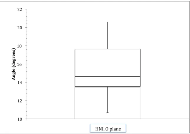
between the HNI plane and the occlusal plane was determined to be 15.5o (Std Dev= 2.7o,
95% CI: 14.7o to 16.2o). The mean angle difference between the Frankfort Horizontal and
occlusal planes was determined to be 9.7o (Std Dev= 5.6o, 95% CI: 8.1o to 11.3o). The
angulation difference between Camper’s and occlusal plane was 6o (Std Dev= 3.2o, 95% CI:
5.0o to 6.9o) (Table 3).
Figure 2 showed the linear measurements from mid hamular notch and ANS to the
anterior determinant of the occlusal plane. The angulation difference between HNI and the
occlusal planes was illustrated in Figure 3. Boxplots in Figure 2 and 3 were calculated using
quartile percentages and median values.
Table 1: List of inclusion and exclusion criteria.
***21 years of age was chosen to ensure that the patients have completed their growth process and 50 years old was an arbitrary cut off age.
Table 2: Anatomical structures and dental landmarks.
Table 3: Mean distances and angulations between landmarks and reference planes.
Inclusion Criteria: Exclusion Criteria
Patients were between the ages of 21 to 50 years old***
Patients who have had full mouth rehabilitation
Patients with 28-32 natural teeth Patients who have had orthognathic repositioning surgery
Patients who have severe skeletal Class II and Class III malocclusion
Anatomical Structures Dental Landmarks
Left and Right Porions Incisal Edge of Central Incisors
Left and Right Orbitales Mesiolingual Cusps of Maxillary 1St Molars
Left and Right Hamular Notches
Anterior Nasal Spine (ANS)
Variables: Mean Values
(Std Dev)
95% CI ANS to Mid Incisal Edge (mm) 29.2 (3) 28.3 – 30.0 Mid Hamular Notch to Mid Incisal Edge (mm) 58.5 (3.2) 57.6 - 59.4 Angle between HNI and Occlusal planes (o) 15.5(2.7) 14.7 - 16.2 Frankfort Horizontal to Occlusal plane (o) 9.7 (5.6) 8.1 - 11.3
Figure 1: Simplant Orthodontics and Orthognathics software was used to identify
Figure 2: Distance (in mm) between line mid hamular notch and line mid incisal edge of maxillary central incisors (left). Distance (in mm) between anterior nasal spine (ANS) to line mid incisal edge of maxillary central incisors (right).
20 25 30 35 40 45 50 55 60 65 70
HN_I edge ANS_Mid I
D ist an ce ( m m )
Figure 3: Angulation (in degrees) between HNI and occlusal planes.
10 12 14 16 18 20 22
HNMIE_O plane
A
n
gl
e
(d
egr
ee
s)
DISCUSSION
The occlusal plane is defined as “the average plane established by the incisal and
occlusal surfaces of the teeth” and it is highly significant in achieving esthetics, phonetics
and re-establishment of lost vertical dimension (27). The reconstruction of natural occlusal
plane in edentulous mouth restores the normal function of cheeks, tongue muscles and other
surrounding structures (28, 29). Without proper orientation, the task of locating the occlusal
plane is challenging, especially in a digital environment. This study offers an alternative
method to determine the location of the occlusal plane through the use of CBCT scans.
Using data collected from 50 anonymous CBCT scans, the angulations and linear
relationships between anatomical structures and dental landmarks were determined. The
incisal edge of the occlusal plane is established by a linear measurement from ANS to mid
Incisal edge of maxillary central incisors; this distance has a mean value of 29.2mm with a
standard deviation of 3mm. The angle of the natural occlusal plane is 15.5o with a standard
deviation of 2.7o, from the HNI plane (Figure 4).
In addition to determining the location of occlusal plane in relation to bony
landmarks, this study also investigated the angulation difference between occlusal plane and
Camper’s and Frankfort Horizontal planes. In this study, the mean angle difference between
Frankfort Horizontal and Occlusal planes was determined to be 9.7o, which was corroborated
angulation of 9.43° in dentulous and 8.53° in edentulous subjects (30). The angular
difference between Camper’s and natural occlusal plane was to be 6.0o in this study. Van
Niekerk et al. conducted a cephalometric study on 33 edentulous patients and found the
angulation difference between occlusal plane and Camper’s plane to be 3.45°. However
Koller et al., and Karkazis and Polyzois reported it as 7.00° and 10.00° respectively (31, 32,
33).
The data from this study provided the linear and angular dimensions needed for the
establishment of natural occlusal plane and it afforded an alternate method to locate the
occlusal plane in-leu of using analog face-bow transfer. The precise measurement acquired
from CBCT scans enabled dentists and technicians to locate the occlusal plane for digital
denture fabrication in a digital environment.
The limitation of this research project may be due to its sample size of 50 patients.
Further verification of these angulations and linear measurements need to be performed
through a larger sample size of CBCT data of adults who are free of dental and skeletal
CONCLUSIONS
With the current paradigm shift in dentistry from analog to digital setting, the ability
to identify the location and angulation of natural occlusal plane digitally is critical to digital
denture fabrication. Distance and angulation relationships between stable anatomical
structures and dental landmarks will provide dentists with the ability to locate the position
and orientation of a patient’s natural occlusal plane without the use of stone models and
analog face-bow. The results of this study can provide dental clinics and laboratories the
ability to fabricate digital dentures in a true digital environment.
Published studies have measured angulation relationships between Frankfort
Horizontal or Camper’s plane and the occlusal plane, which could be used to establish the
orientation of a patient’s occlusal plane, especially in edentulous patients. However, these
studies have illustrated a large variance in the degrees of angulation. The angulation
relationship between the hamular notch-incisal edge (HNI) plane and the occlusal plane
established in this study provide another modality for orientation of occlusal plane. This
angle is confined within the skull and has a low variance. It appears to be a relatively stable
and reliable angle of reference in establishing proper orientation of the occlusal plane.
Current advancement in technology has equipped the dental community with
occlusal plane in edentulous mouth. The technical and clinical importance of this study
findings could be extrapolated to virtual teeth set-up in a digital wax-up, the establishment of
occlusal plane in prosthodontically driven surgical guide and the re-establishment of occlusal
plane in full mouth rehabilitation. Hence, minimizing the guesswork from prosthodontics
REFERENCES
1. Shallhorn RG. A study of the arbitrary center and kinematic center of rotation for face-bow mountings. J Prosthet Dent 7:162, 1957.
2. Strohave, R.A. and Ryan J.R. New face-bow simplifies routine use and dental laboratory cooperation. J Prosthet Dent. 60:638,1988.
3. Beyron AG and Bodner GH. Variation in the location of arbitrary and true hinge axis points. J Prosthet Dent 11:224, 1961
4. McCullom, B. B. Fundamentals Involved in Prescribing Restorative Dental Remedies, D. Items Interest 61:522, 641, 724, 852, 942, 1939.
5. Eberle, William. A Study of Centric Relation As Recorded in a Supine Rest Position, J.A.D.A. 42:15, 1951.
6. . Walker PM. Discrepancies between arbitrary and the true hinge. J Prosthet Dent 43:279, 1980
7. Joyce F.P, Donald R.N, and James T. W. Accuracy of an earpiece facie-bow. J Prosthet Dent, 1985.
8. Lauriztzen AG and Bodner GH. Variations in the location of arbitrary and true hinge axis points. J Prosthet Dent 11:224, 1961.
9. Arstad, T. The of the Dentition Capsular Ligaments in Relationship of
Temporomandibular Joint and Retrusion Facets to Mandibular Movements, Oslo. 1954.
10. Schuyler, C. Factors of Occlusion Applicable to Restorative Dentistry, J Prosthet. Dent. 3:772, 1953.
11. Schlosser, R.O, and Gehl, D.H. Complete Denture Prosthesis, ed. 3, Philadelphia and London, 1953, W.B. Saunders Company.
12. Weinberg L.A. An Evaluation of the Face-bow Mounting. J. Prosthet. Dent. Jan.-Feb. 1961
13. Logan, J. G. Indispensability of the Face-Bow, D. Digest 32:537, 1926.
14. Stansbery, C. J. Futility of the Face-Bow, J.A.D.A. 15:1467, 1928.
17. Kawai Y., Murakami H., Shariati B., Klemetti E., Blomfield J., Billette L., Lund J., Feine, J. Do traditional techniques produce better conventional complete dentures than simplified techniques? J. Dent. 2005:33. 659-668
18. Hyde TP, McCord JF. Survey of prosthodontic impression procedures for complete dentures in general dental practice in the United Kingdom. J Prosthet Dent, 1999; 81:295–9.
19. Clark DM, Oyen OJ, Feil P. The use of specific dental school- taught restorative techniques by practicing clinicians. J of Dent Edu, 2001;65:760–5.
20. Duncan JP and Taylor TD. Teaching an abbreviated impression technique for complete dentures in an undergraduate dental curriculum. J of Prosthet Dent 2001; 85:121–5.
21. Clark RK. The future of teaching of complete denture construction to undergraduates. British Dental Journal 2002;193:13–14.
22. Szentpétery A. Computer aided dynamic correction of digitized occlusal surfaces. J Gnathol 1997;16:53-60. 11.
23. Gaertner C, Kordass B. The virtual articulator: development and evaluation. Int J Comput Dent 2003;6:11-23.
24. Bidra, Taylor and Agar. Computer-aided technology for fabricating complete dentures: Systematic review of historical background, current status, and future perspectives. J Prosthet Dent, 2013.
25. Kalathingal S, Mol A, Tyndall D, Caplan D. In vitro assessment of cone beam local computed tomography for proximal caries detection. Oral Surg Oral Med Oral Pathol Oral Radiol Endod, 104 (2007), pp. 699-704
26. Tyndall D, Price J, Tetratis S, Ganz S, Hildebolt C, Scarfe W. Position statement of the American Academy of Oral and Maxillofacial Radiology on selection criteria for the use of radiology in dental implantology with emphasis on cone beam computed tomography. Oral
Surg Oral Med Oral Pathol Oral Radiol, 113 (2012), pp. 817-826
27. Seifert D, Jerolimov V, Carek V, Ibrahimagic L. Relation of the reference planes for orientation of the prosthetic plane. Acta Stomatol Croat 2000;34:413-6.
28. Landa JC. A scientific approach to the study of the temporomendibular joint and its relation to occlusal disharmonies. J Prosthet Dent 1957;7:170-4.
29. Lang B, Swartz W. Clinical Dentistry. 5th ed. Hagerstown: Harper and Row; 1979. p.
orientation of the occlusal plane and the determination of the vertical dimension of occlusion in edentulous patients. J Oral Rehabil 1992;19:413-25.
32. Karkazis HC, Polyzois GL. A study of the occlusal plane orientation in complete denture construction. J Oral Rehabil 1987;14:399-404.