Volume 2, Issue 9, September 2013
Page 174
A
BSTRACTThis paper presents an algorithm for solving the multi-objective reactive power dispatch problem in a power system. Model analysis of the system is used for static voltage stability assessment. Loss minimization and maximization of voltage stability margin are taken as objectives .Generator terminal voltages, reactive power generation of the capacitor banks and tap changing transformer settings are taken as the optimization variables. The proposed approach employs cat swarm optimization (CSO) algorithm for optimal settings of RPD control variables. The proposed approach is examined and tested on the standard IEEE 30-bus test system with different objectives that reflect power loss minimization, voltage profile improvement, and voltage stability enhancement. The results demonstrate the potential of the proposed approach and show its effectiveness and robust ness to solve the RPD .
Keywords: Reactivepower dispatch , loss minimization, voltage stability enhancement, cat swarm optimization .
1.
I
NTRODUCTIONOne of the important operating requirements of a reliable power system is to maintain the voltage within the permissible ranges to ensure a high quality of customer service. The optimal power flow (OPF) has been widely used for both the operation and planning of a power system .Therefore, a typical OPF solution adjusting the appropriate control variables[1], so that a specific objective in operating a power system network is Optimized(maximizing or minimizing) with respect to the power system constraints, detected by electrical network.
The problem that has to be solved in a reactive power optimization is to determine the required reactive generation at various locations so as to determine the required reactive generation at various locations so as to optimize the objective function. Here the reactive power dispatch problem [2] involves best utilization of the existing generator bus voltage magnitude, transformer tap setting and the output of reactive power sources so as to minimize the loss and to enhance the voltage stability of the system.
Cat Swarm Optimization (CSO) is proposed in this paper .One of the more recent optimization algorithm based on swarm intelligence is the Cat Swarm Optimization (CSO) algorithm[3]-[4]. The CSO algorithm was developed based on the common behavior of cats. It has been found that cats spend most of their time resting and observing their environment rather that running after things as this leads to excessive use of energy resources. To reflect these two important behavioral characteristics of the cats, the algorithm is divided into two sub-modes and CSO refers to these behavioral
characteristics as ―seeking mode and ―tracing mode, which represent two different procedures in the algorithm.
Tracing mode models the behavior of the cats when running after a target while the seeking mode models the behavior of the cats when resting and observing their environment.
The proposed algorithm identifies the optimal values of generation bus voltage magnitudes, transformer tap setting and the output of the reactive power sources so as to minimize the transmission loss and to improve the voltage stability. The effectiveness of the proposed approach is demonstrated through IEEE-30 bus system. The test results show the proposed algorithm gives better results with less computational burden and is fairly consistent in reaching the near optimal solution.
The performance of CSO algorithm was compared to that of different heuristic techniques .it is found that ,the convergence speed of CSO is significantly better than that of DE[1],PSO[6]-[10], and evolutionary algorithms(EAs)[13]-[14].it is found that ,CSO is the best performing algorithm as it finds the lowest fitness value for the most of the problems considered in that study.
2.
PROBLEM
FORMULATION
2.1 Nomenclature :
loss
P
Network real power lossi
P
,Q
iReal and reactive powers injected into network at bus iPower loss minimization using cat swarm
optimization
P.Surya kumari1, Dr.P.Kantarao 2
Volume 2, Issue 9, September 2013
Page 175
ij
G
,
B
ijMutual conductance and susceptance between bus i and bus jii
G
,
B
ii Self- conductance and susceptance of bus igi
Q
Reactive power generation at bus i ciQ
Reactive power generated byi
th capacitor bank kt
Tap setting of transformer at branch ki
V
Voltage magnitude at bus i jV
Voltage magnitude at bus jij
Voltage angle difference between bus i and bus jl
S
Apparent power flow through thel
thbranch kg
Conductance of branch kB
N
Total number of buses1
B
N
Total number of buses excluding slack bus PQN
Number of PQ busesg
N
Number of generator busesC
N
Number of capacitor banks TN
Number of tap-setting transformer branches lN
Number of branches in the systemi
Voltage phase angle ofi
th generator busThe RPD problem aims at minimizing the real power loss in a power system while satisfying the unit and system constraints. This goal is achieved by proper adjustment of reactive power variables like generator voltage magnitudes (V
gi), reactive power generation of capacitor banks (Qci) and transformer tap settings (tk). The optimal reactive power
dispatch problem is formulated as an optimization problem in which a specific objective function is minimized while satisfying a number of Equality and inequality [11]-[14].
2.2 Real power losses
:
This is mathematically stated asMinimize (1)
The real power loss given by (1) is a non-linear function of bus voltages and phase angles which are a function of control variables. The minimization problem is subjected to the following equality and inequality constraints.
2.3 Equality Constraints
These constrains represents the typical load flow equations
(2)
(3)
2.4 Inequality Constraints
These constraints represent the system operating constraints. Generator bus voltages (Vgi), reactive power generated by
the capacitor (Qci), transformer tap setting (tk), are control variables and they are self restricted. Load bus voltages (Vload)
reactive power generation of generator (Qgi) and line flow limit (Sl) are state variables, whose limits are Satisfied by
adding a penalty terms in the objective function.
i j i j ij
k
loss
g
v
v
v
v
P
j i k Nl k
cos
2
2 2 ,
1
,
0
sin
cos
1
B B j ij ij ij ij j ii
i
N
N
B
G
V
V
P
PQB j ij ij ij ij j i
i
i
N
N
B
G
V
V
Q
Volume 2, Issue 9, September 2013
Page 176
These constraints are formulated asi) voltage limits
(4) ii) Generator reactive power capability limit
(5)
iii) Capacitor reactive power generation limit
(6)
iv) Transformer tap setting limit
(7)
v) Transmission line flow limit
(8) vi) Voltage stability constraint
L
max
L
min (9)The voltage stability index given in Equation (9) is evaluated as follows, First, the L-indices [19] of all the load buses in the system are computed using the expression(10):
g N i j i ji j i ji jV
V
F
L
1)
(
1
(10)The values of
F
jiare obtained from the matrix FLG,
Where,
[
]
1[
]
LG LLLG
Y
Y
F
(11)The maximum of the L indices (Lmax ) gives the proximity of the system to voltage collapse. The bus with the highest L index value will be the most vulnerable bus in the system which need critical reactive power support.
3. Cat swarm optimization
3.1 Overview
CSO algorithm[2] is divided into two sub models based on two of major behavioural of traits of cats. These are termed as “Seeking mode” and “Tracing mode”.
Seeking mode has four essential factors .Such as SMP,SRD,CDC,SPC Which are designed as follows .
Seeking Memory pool (SMP):- It is used to define the size of Seeking memory of each cat, indication any points sort by cat.
Seeking Rang of Selected Dimensions (SRD):- It is used to declare mutative ration for selected dimensions. While in seeking mode; if a dimension is selected for mutation, the difference between old and new ones may not be out of range ,the range defines by SRD.
Counts of Dimensions to Change (CDC):- It is used tell how many dimensions to will be varied. All these factors play an important roles in seeking mode.
Self Position Consideration (SPC):- It is a Boolean valued variable, and indicates whether the point at which the cat is already standing will be one of the candidate point to move to.SPC cannot influence SMP.
3.2. Seeking Mode: Resting and Observing
The seeking mode of the CSO algorithm models the behaviour of the cats during the period of resting but staying alert-observing its environment for its next move .
The seeking mode of the CSO algorithm can be described as follows B
i i
i
V
V
i
N
V
min
max;
g gi
gi
gi
Q
Q
i
N
Q
min
max;
c ci
ci
ci
Q
Q
i
N
Q
min
max;
T
N
k
t
t
t
kmin
k
kmax;
l l
l
S
l
N
Volume 2, Issue 9, September 2013
Page 177
Step 1:-Make j copies of the present position of each catk , where j=SMP. if the value of SPC is true. let
j=(SMP=1),then retain present position as one of the candidates.
Step 2:- For each copy according to CDC add or subtract SRD percent values and replace the old ones. Step 3:-Calculate the fitness values (FS) of all candidate points.
Step 4:-If all the FS[3] are not exactly equal calculate the selecting probability(12) of each candidate point .otherwise set all the selecting probability of each candidate point to 1.
where i j
FS FS
FS FS
Pi i b
, 0
min max
(12)
If the global of the fitness is to find the minimum solution .FSb=FSmax , otherwise FSb=FSmin.
Step 5:- Randomly pick the point to move to form the candidate points, and replace the position of catk .
3.3.Tracing Mode.:- Running after a target
Step1:- update the velocities for every dimension (Vid) according to eq (13)
Step 2:- check if the velocities are in the range of maximum velocity is over-range, it is set equal to the equal. Step 3:- update the position of catk according to eq (14)
gd id
id
id
W
V
C
r
P
X
V
*
*
*
(13)Where ,W is inertia weight ,Pgd is position of cat, who has the best fitness value. Xid is the position of catk, C is constant
r is a random value in the range of [0,1].
id id id
X
V
X
(14)3.3 CSO flow chart
Fig
1.CSO flow chart
4.Results
Volume 2, Issue 9, September 2013
Page 178
Fig2: Single line diagram of IEEE-30 bus test system
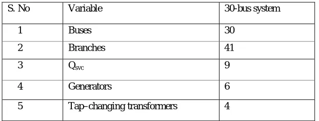
Table1: System description of IEEE 30 bus test system
Variable limits of control variables are given in Table2
Table 2: Control variable limits
RPD with loss minimization objective . Here the CSO algorithm was applied to identify the optimal control variables of the system under base-load condition, with loss minimization and without considering the voltage stability of the system. It was run with different control parameter settings and the minimization solution was obtained with the following parameter setting s are shown in Table3
Table3: CSO Parameters for best results of optimal power flow for IEEE 30-bus system
S.No Parameters Values
1
2
3
Populations
Iterations
Copies
170
180
30
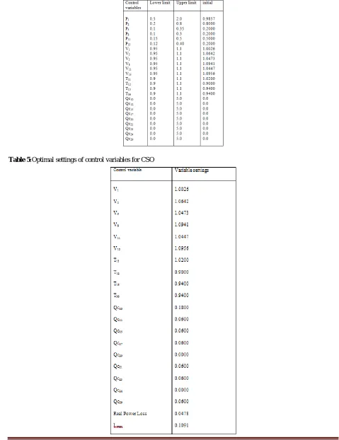
The minimum and maximum limits for the control variables along with the initial settings Table 4 :The optimal values of the control variables along with the minimum loss obtained are given in Table 5.Corresponding to this control variable
S. No Variable 30-bus system
1 Buses 30
2 Branches 41
3 Qsvc 9
4 Generators 6
5 Tap–changing transformers 4
S.No Control variable limits Limits
1
2
3
Generator voltage (Vg)
Tap setting(tk)
MVAR by static compensators (Qsvc)
(0.95-1.1) p.u.
(0.95 -1.1)p.u.
Volume 2, Issue 9, September 2013
Page 179
setting, it was found that there are no limit violations in any of the state variables. The minimum loss obtained by the proposed method is less than the values presented in the other papers. It is tabulated in the Table 5Table 4 :The minimum and maximum limits for the control variables along with the initial settings
Volume 2, Issue 9, September 2013
Page 180
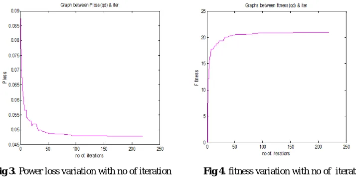
Fig 3. Power loss variation with no of iteration Fig 4. fitness variation with no of iterations
Fig 3,4 shows the graph between power loss and fitness variations with respective to no iterations
Table 6: Comparison of Power Losses for different methods
Method Minimum Power loss(pu)
Evolutionary programming[10]
DE[1]
Proposed algorithm
5.0159
0.0485
0.0478
5.Conclusions
In this paper ,CSO optimization algorithm has been proposed ,developed and successfully applied to solve reactive power dispatch problem .The RPD has been formulated as a constrained optimization problem where several objective functions have been considered to minimize the power losses, to improve the voltage profile ,and to enhance the voltage stability. The proposed approach has been tested and examined on the standard IEEE 30-bus test system. the results demonstrate the effectiveness and robustness of the proposed algorithm to solve RPD problem. This paper shows that such excellent results with different objective functions shows that makes the proposed CSO optimization technique is good in dealing with power system optimization problems.
References
[1] K. Vaisakh and P. K. Rao, “Differential Evolution based optimal reactive power dispatch for voltage stability enhancement,” Journal of Theoretical and Applied Information Technology, pp. 700-709, 2008.
[2] P.Aruna Jeyanthy and Dr.D.Devaraj, “Optimal Reactive Power Dispatch for Voltage Stability enhancement using real coded genetic algorithm”, International Journal of Computer and Electrical Engineering, Vol 2, No.4, Aug 2010, 1793-8163.
[3] S-C Chu, P-W Tsai and J-S. Pan. Cat Swarm optimization. Proceedings of the 9th Pacific Rim International Conference on Artificial Intelligence, LNAI 4099, Guilin,(2006), pp. 854-858.
[4] J.-C. Hwang, J.-C. Chen and J.-S. Pan. CSO and PSO to Solve Optimal Contract Capacity for High Tension Customers. Proceedings of 8th International Conference on Power Electronics and Drive Systems, PEDS-2009, (2009), pp. 76-81.
[5] A.A.Abou El Ela,M.A. Abido,S.R.Spea,” Differential evolution algorithm for optimal reactive power dispatch,” Journal of Electrical Power and Energy Systems Vol. 81,2011, pp 485-464.
[6] Particle Swarm Optimization Approach for Solving the Discrete OPF Problem Considering the Valve Loading Effects”, IEEE Transactions on Power Systems, Issue 4,Vol. 22, pp.2030 – 2038, 2007.
Volume 2, Issue 9, September 2013
Page 181
[8] B. Zhao, C.X. Guo and Y.J. Cao, “Improved particle swam optimization algorithm for OPF problems”, IEEE-PES Power Systems Conference and Exposition, Vol. 1, pp.233 - 238, 10-13 October 2004.
[9] Nakhon Ratchasima . Power Loss Minimization Using Optimal Power Flow Based on Particle Swarm Optimization., U. Leeton University of Technology, THAILAND 30000.
[10]Granville, S. 1994.’Optimal Reactive Power Dispatch through Interior Point Methods’ IEEE Trans. on PowerSystems Vol.9.No.1,pp.98-105.
[11]H. W. Dommel and W. F. Tinny, “Optimal power flow solutions,” IEEE trans. on power app & systems, 87 , 1968, pp 1866-1876.
[12]Wu Q.H. and Ma J. T.(1995) ‘Power System Optimal Reactive Power Dispatch Using Evolutionary Programming’, IEEE Trans on power system, Aug,Vol.10.No.3,pp.1243-1249.
[13]T.Jayabarathi, K.Jayaprakash, D.N.Jeyakumar, T.Raghunathan, “Evolutionary Programming Techniques For Different Kinds Of Economic Dispatch Problems”, Electric Power Systems Research, Vol. 73, 2005, pp. 169-176. [14]Rainer Storn, Kenneth Price, “Differential Evolution – A Simple and Efficient Adaptive Scheme for Global
Optimization Over Continuous Spaces” TR-95-012, March 1995.
[15]Dervis Karaboga, Selcuk Okdem, “A Simple and Global Optimization Algorithm For Engineering Problems: Differential Evolution Algorithm”, Turk J Elec. Engin.,Vol. 12, No.1, 2004, pp. 53-60.
[16]K. Iba, “Reactive power optimization by genetic algorithm,” IEEE trans. on power systems, Vol. 9 No. 2, 1994 , pp 685-692.
[17]Lee K.Y. Park Y.M. and Ortiz J.L. (1985). ‘A United Approach to Optimal Real and Reactive Power dispatch’,
IEEE Trans. On Power Apparatus and Systems, May, Vol.PAS.104, No.5, pp 1147-1153.
[18]Granville, S. 1994.’Optimal Reactive Power Dispatch Through Interior Point Methods’,IEEE Trans. on Power Systems Vol.9.No.1,pp.98-105.
[19]S.Durairaj, D.Devaraj, P.S.Kannan ,’ Genetic algorithm applications to optimal reactive power dispatch with voltage stability enhancement’ , IE(I) Journal-EL Vol 87,September 2006.
AUTHOR
Dr.P.KANTARAO born in Andhra Pradesh, India, in 1969. He received the B.Tech. M.Tech degree in Electrical and Electronics Engineering from Affiliated College of Sri Venkateswara University, A.P.He has the experience of 22 years teaching Experience. His research areas arein power systems security, stability, load management and voltage stability, and has published more papers in these areas. Currently, he is with the Department of Electrical and Electronics Engineering, in GMR Institute of Technology, Rajam, and Andhra Pradesh as a Professor.