© 2019, IRJET | Impact Factor value: 7.211 | ISO 9001:2008 Certified Journal | Page 4427
UNDERWATER IMAGE ENHANCEMENT USING IMAGE PROCESSING
TECHNIQUE
RADHIKA K R
1, V. VINOD KUMAR
2, S MOHAN
3, Dr. V JAYARAJ
41
PG Scholar, Department of Electronics and communication Engineering, Nehru institute of
Engineering and Technology
2,3
Assistant Professor, Dept. of Electronics and communication Engineering, Nehru institute of
Engineering and Technology
4
Professor And Head, Dept. of Electronics and communication Engineering, Nehru institute of
Engineering and Technology
---***---
ABSTRACT - Image enhancement is the major process inthe image processing techniques. Image enhancement would increase the sharpness and intensity of the underwater images. By increasing the factors of the pixels, the object can be visible clearly in the underwater images. Photograph fusion is the mixture of two or extra unique graphics to kind new snapshot through making use of a detailed algorithm. Photograph fusion is the approach of producing a single fused snapshot utilising a set of input pics which are assumed to be registered. Enter image would be multi-sensor, multimodal, multifocal or multi-temporal. This paper grants a literature overview on one of the most photo fusion procedures and photograph enhancement systems. The input image is first pre-processed. Then HWD transform is applied on it for sharpening the image. The low-frequency background is removed using a highpass filter. Image histograms are then mapped based on the intermediate color channel to reduce the gap between the inferior and dominant color channels. Then Wavelet fusion is applied followed by adaptive local histogram specification process. The resultant images processed through the proposed approach could be further used for detection and recognition to extract more valuable information. Image Enhancement is to procedure the input image in any such means that the output image is more compatible for interpretation by the humans as well as by way of machines.
KEYWORDS: HWD transform, highpass filter, Wavelet fusion, Image processing
SECTION I
INTRODUCTION
Image enhancement is the technique for processing the input underwater image to result it in a proper and clearly visible image which can be used for the various research applications. This image enhancement technique is helpful for improving the information which is present in the image. This image alters the visuality of the mage which is useful for improving the image information for the observer. Image enhancement in the
underwater images would be difficult task as it would eliminates the information which is present inside the image while the enhancement process is carried out. Image enhancement identify the feature of the image. Enhancement process is carried out by increasing the image features like edge, contrast to increase the photographs for the research and study. Qualitative objective approach is used for the enhancing process to show the impressive images. Image enhancement includes many operations such as contrast stretching, noise clipping process, pseudo-coloring, noise filtering technique. Active range of the features of image have been amplified by the various detected features. Various existing algorithm of the enhancement process shows the images have the poor quality because of the nature of the light. When the light is entering into the water ,the light get refracted and it was absorbed and scattered as the water is denser medium than air. This light drops occurs when the light entered into the water and got scattered into the different directions. Scattering from the light caused by the blurring effect of the light and the reduction of color contrast. These effects changes in water in underwater images are not only by the nature of the water but also by the organisms and other material which is present in the water. Light have the different intensity and different wavelength according to the blue, green, red colors present in the water.
SECTION II
LITERATURE SURVEY
© 2019, IRJET | Impact Factor value: 7.211 | ISO 9001:2008 Certified Journal | Page 4428
mastery of either the blue or the green shading. unnumerable deliberation space approaches have been created to isolate out the previously mentioned photo magnificent hindrances. To represent shading cast disservice, Iqbal et al [7] arranged a shading leveling methodology to help the superb of submerged film. The
strategy includes computation of the For
correspondence scale component of the overwhelming shading plane inside the RGB shading zone for adjusting the rest of. Be that as it may, daze shading leveling [9] Furthermore debases the shading lovely of the picture that is very unfortunate. One diverse strategy to shrink color cast is predicated on the Beer's enactment. Lager's law is regularly used to right the constituent force by exploitation calculative the amount of daylight assimilation in water. On this framework, missing wavelengths square measure determined assumptive that every one of the items among the scene square measure at consistent profundity. despite the fact that this procedure improves the standard of photo, assumptive an equivalent medium and equivalent profundity of all items in an exceedingly scene probably won't be legitimate through and through events. Also, the shading additional items depend upon various reasons like profundity of the scene, measurement of water particles, thickness of water medium and close
temperature [10], that requires chosen
institutionalization of the improvement parameters. To check these issues, strategies dependent on the material science of photograph arrangement are created to neutralise the adverse impacts of ingestion and backscattering. Schechner and Karpel [3] proposed a calculation dependent on a gathering of photographs by methods for a polarizer at one of a kind edges to invalidate the physical aftereffects of picture quality debasement. Improvement in lights and sensing programs [12] for enlightening an article before taking pictures of the photo is a substitute method in those ways. A distinctive remarkable arrangement of tending to the enhancement side is to utilize a focal point channel [13], whereby upgrade of the picture is guaranteed
because of decrements in assimilation and
backscattering results. Considering the focal point channel ingests a component of enlightenment, the technique is subsequently more correct for earthly photo improvement [3, 12, 14].Statistical methodologies [15] are additionally utilized for shading amendment using Markov irregular subject with the guide of relating the prior color data with the present one. In these methods, the fundamental supposition is that the neighboring scenes for all intents and purposes much like that of the current picture. I observe, amazing usage of onboard electrical life is incredibly primary for duplicated mission perseverance of AUVs, and for that reason, onboard lights are ordinarily flashed best at the time of the photo catch, fundamental to lacking ability of the neighboring scene. Earlier understanding may not likewise be like the present one in heterogeneous
submerged atmosphere – a method of reasoning that could render improvement arranged on factual ways infeasible. Scientists have additionally dealt with shading photo improvement using in excess of a couple thresholding plans [16] which would never again be important all inclusive as predefining the edge esteems may not be reasonable for pixel influenced by shading fashioned.
SECTION III
METHODOLOGY
Basics steps for image processing as shown in the figure 1
Figure 1 Image processing steps Photograph FUSION methods
A. Image acquisition
Input image is captured from the underwater through the camera. This captured image is in the form of RGB image which consists of red, green and blue region. The captured image undergoes the pre-processing stage the bigger the pixel values the more in center of attention the photograph. As a consequence this algorithm chooses the infocus areas from each and every enter photograph through picking the finest value for each and every pixel, resulting in particularly targeted output. The worth of the pixel P (i, j) of each picture is taken and when compared to each other.
B. Pre-processing
The pre-processing stages in image processing consists of various number of process which depends according to the input image. The input image which is taken through some source undergoes the pre-processing stages. Input image is the RGB image.RGB image is converted towards the gray scale image which have the pixel range of 0 to 255.Filtering process which comes under the pre-processing stage. This filtering process reduces the noise which is present in the image.
C .Detection
The detection process which includes the
enhancement of image which is taken as a input image. In the proposed work enhancement process is
Image acquisition
Pre-processing (Image
© 2019, IRJET | Impact Factor value: 7.211 | ISO 9001:2008 Certified Journal | Page 4429
carried out using HWD transform technique. Using this technique noise can be removed and the enhancement of image will be higher.
SECTION IV
PROPOSED WORK
[image:3.595.378.516.222.314.2]The block diagram of the of the proposed work is as shown in the figure 4.1
Figure 4.1 PROPOSED WORK
PRE-PROCESSING
Grey scale is simply reducing complexity: from a 3D pixel value (R,G,B) to a 1D value. Grey scale is a range of shades of grey without apparent color. Grey scale Images are more suitable for many applications such as edge detection. The pre-processing stage consists of following stages
Figure 4.2 INPUT IMAGE
Figure 4.3GRAY SCALE IMAGE
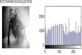
HWD TRANSFORM
The hybrid wavelet transform and directional filter banks (HWD).HWD is a class of non-redundant, directional, hybrid wavelet transform HWD is a two-tier transform, where initially a conventional DWT is applied, followed by the directional filters on the detail subbands. The output of the histogram equalization is shown in the figure 4.4 HWD transform is shown in the figure 4.5
[image:3.595.50.264.226.297.2]Figure 4.4 Histogram Equalization
Figure 4.5.1 Filtered image
Figure 4.5.2 HWD transform
BACKGROUND SUBTRACTION
The image will be first converted into natural
logarithm domain before the Fast Fourier
transformation (FFT) is applied. The high pass filter
Input image Preprocessing HWD Transform
Background removal (Butterworth
filter)
Histogram mapping Wavelet fusion
[image:3.595.335.523.490.676.2]© 2019, IRJET | Impact Factor value: 7.211 | ISO 9001:2008 Certified Journal | Page 4430
is then applied using the Butterworth filter. Butterworth high-pass filter is an effective high-pass filter to eliminate low frequency signal which is normally used for background removal.
Figure 4.6 Background removal
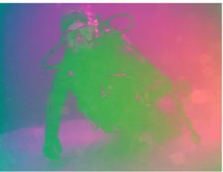
HISTOGRAM MAPPING
Red color channel is normally the inferior color channels while green and blue color channels are the dominant color channels. The percentage of red color channel is the lowest while highest color channel percentage commonly taken by green or blue color channel. The proposed work consists of following work in the figure 4.7
Figure 4.7 HISTOGRAM MAPPING
ENHANCED IMAGE
[image:4.595.92.223.155.296.2]These histograms will produce two independent images which have under- and over-enhanced effects. Therefore, for three basic histogram channels of red, green, and blue will produce six independent histograms.
Figure 4.8 Fusion image
Figure 4.9 Enhanced image
PERFORMANCE METRICS
Thus, the proposed work consists of the below error rate and the accuracy range. Thus the enhancement technique can be carried out with the higher accuracy range.
SL.NO PARAMETER IMAGE VALUE
1 ENTROPY 7.02665
2 ELAPSED
TIME 35.628 S
3 MSE 46010
[image:4.595.79.241.462.587.2]4 PSNR 9.2498
Figure 5 Performance metrics
CONCLUSION
The proposed HTIBF method is an underwater image enhancement technique which is normally used as a pre-processing method for object detection and recognition of underwater image. HTIBF method consists of integrated steps namely pre-processing, HWD transform, background removal, histogram mapping, wavelet fusion, and adaptive local histogram specification.
© 2019, IRJET | Impact Factor value: 7.211 | ISO 9001:2008 Certified Journal | Page 4431
REFERENCES
[1] Chiang J Y and Chen Ying-Ching 2012 Underwater image enhancement by wavelength compensation and dehazing. IEEE Trans. Image Process. 21(4): 1756–1769 [2] Pegau W S, Gray D and Zaneveld J R V 1997 Absorption and attenuation of visible and near-infrared light in water: Dependence on temperature and salinity. Appl. Opt. 36(24): 6035– 6046
[3] Schechner Y Y and Karpel N 2005 Recovery of underwater visibility and structure by polarization analysis. IEEE J. Oceanic Eng. 30(3): 570–587
[4] Sedlazeck A and Koch R 2011 Simulating deep sea underwater images using physical models for light attenuation, scattering, and refraction. Vision, Modeling, and Visualization Workshop, pp 49–56
[5] Trucco E and Olmos-Antillon A T 2006 Self-tuning underwater image restoration. IEEE J. Oceanic Eng. 31(2): 511–519
[6] Iqbal K, Salam R A, Osman A and Talib A Z 2007 Underwater image enhancement using an integrated colour model. IAENG Int. J. Comput. Sci. 32(2): 239–244 [7] Iqbal K, Odetayo M, James A, Salam R A and Talib A 2010 Enhancing the low quality images using unsupervised colour correction method. IEEE Int. Conf. Syst. Man Cybern. (SMC), pp 1703–1709
[8] Kwok N, Wang D, Jia X, Chen S, Fang G and Ha Q 2011 Gray world based color correction and intensity preservation for image enhancement. Int. Congress Image Signal Process. (CISP) 2: 994–998
[9] Provenzi E, Gatta C, Fierro M and Rizzi A 2008 A spatially variant white-patch and gray-world method for color image enhancement driven by local contrast. IEEE Trans. Pattern Anal. Mach. Intell. 30(10): 1757–1770
[10] Ahlen J, Sundgren D, Lindell T and Bengtsson E 2005 Dissolved organic matters impact on colour reconstruction in underwater images. Image Anal. pp 1148–1156
[11] Chikane V and Fuh C-S 2006 Automatic white balance for digital still cameras. J. Inf. Sci. Eng. 22(3): 497–509
[12] Gupta M, Narasimhan S G and Schechner Y Y 2008 On controlling light transport in poor visibility environments. IEEE Conference on Computer Vision and Pattern Recognition pp 1–8
[13] Bier E, Stone M and Pier K 1997 Enhanced illustration using magic lens filters. IEEE Comput. Graph. Appl. 17(6): 62–70
[14] Tan K and Oakley J P 2001 Physics-based approach to color image enhancement in poor visibility conditions. J. Opt. Soc. Am. A 18(10): 2460–2467
[15] Torres-Mendez L A and Dudek G 2005 A statistical learningbased method for color correction of underwater images. In: Gelbukh A and Monroy R (Eds.)Research on computer science Vol. 17, Advances in artificial intelligence theory, pp 151–160
[16] Lam C 2011 Image enhancement using thresholding techniques and histogram equalization. PhD thesis, University of California, Irvine
[17] Karunakaran V and Venugopal T 1998 The Weierstrass transform for a class of generalized functions. J. Math. Anal. Appl. 220(2): 508–527
[18] Perona P and Malik J 1990 Scale-space and edge detection using anisotropic diffusion. IEEE Trans. Pattern Anal. Mach. Intell. 12(7): 629–639
[19] Gerig G, Kubler O, Kikinis R and Jolesz F A 1992 Nonlinear anisotropic filtering of MRI data. IEEE Trans. Med. Imaging 11(2): 221–232
[20] Loupas T, McDicken W N and Allan P L 1989 An adaptive weighted median filter for speckle suppression in medical ultrasonic images. IEEE Trans. Circuits Syst. 36(1): 129–135
[21] Qui F, Berglund J, Jensen J R, Thakkar P and Ren D 2004 Speckle noise reduction in SAR imagery using a local adaptive median filter. GISci. Remote Sensing 41(3): 244–266
[22] Singhai J and Rawat P 2007 Image enhancement method for underwater, ground and satellite images using brightness preserving histogram equalization with maximum entropy. International Conference on Conference on Computational Intelligence and Multimedia Applications 3: 507–512
[23] Pizer S M, Amburn E P, Austin J D, Cromartie R, Geselowitz A, Greer T, terHaarRomeny B, Zimmerman J B and Zuiderveld K 1987 Adaptive histogram equalization and its variations. Computer Vis. Graph. Image Process. 39(3): 355– 368