Date of publication xxxx 00, 0000, date of current version xxxx 00, 0000. Digital Object Identifier 10.1109/ACCESS.2017.DOI
Optimum Deployment of Multiple UAVs
for Coverage Area Maximization in the
Presence of Co-channel Interference
AZIZ A. KHUWAJA1,2, GAN ZHENG3, (Senior Member, IEEE), YUNFEI CHEN1, (Senior Member, IEEE), and WEI FENG4,5, (Senior Member, IEEE)
1School of Engineering, University of Warwick, Coventry CV4 7AL, U.K. (e-mail: A.khuwaja,[email protected]) 2Department of Electrical Engineering, Sukkur IBA University, Sukkur 65200, Pakistan (e-mail: [email protected]) 3
Wolfson School of Mechanical, Electrical, and Manufacturing Engineering, Loughborough University, Loughborough LE11 3TU, U.K. (e-mail: [email protected])
4
Peng Cheng Laboratory, Shenzhen 518000, P.R. China
5
Beijing National Research Center for Information Science and Technology, Tsinghua University, Beijing 100084, P.R. China Corresponding author: Wei Feng (e-mail: [email protected])
This work was supported in part by the Beijing Natural science Foundation (L172041), in part by the National Science Foundation of China (61771286, 61701457, 91638205, 61671478), and in part by the Beijing Innovation Center for Future Chip. The work of G. Zheng was supported in part by the UK EPSRC under grant number EP/N007840/1, and in part by the Leverhulme Trust Research Project Grant under grant number RPG-2017-129.
ABSTRACT The use of unmanned aerial vehicle (UAV) as aerial base stations can provide wireless
communication services in the form of UAV-based small cells (USCs). Thus, the major design challenge that needs to be addressed is the coverage maximization of such USCs in the presence of co-channel interference generated by multiple UAVs operating within a specific target area. Consequently, the efficient deployment strategy is imperative for USCs while optimizing the coverage area performance to compensate the impact of interference. To this end, this paper presents a coordinated multi-UAV strategy in two scenarios. In the first scenario, symmetric placement of UAVs is assumed at a common optimal altitude and transmit power. In the second scenario, asymmetric deployment of UAVs with different altitudes and transmit powers is assumed. Then, the coverage area performance is investigated as a function of separation distance between UAVs which are deployed in a certain geographical area to satisfy a target signal-to-interference-plus-noise ratio (SINR) at the cell boundary. Finally, the system-level performance of a boundary user is studied in terms of the coverage probability. Numerical results unveils that the SINR threshold, the separation distance, and the number of UAVs and their formations should be carefully selected to achieve the maximum coverage area inside and to reduce the unnecessary expansion outside the target area. Thus, this paper provides important design guidelines for the deployment of multiple UAVs in presence of co-channel interference.
INDEX TERMS Coverage area performance, interference management, UAV-based small cells, UAV
communications, UAV separation distance
I. INTRODUCTION
U
NMANNED aerial vehicles (UAVs) equipped with ra-dio transceivers can satisfy the requirements for an aerial communication platform by serving either as a mobile base station or as an airborne relay. Due to their flexible deployment, UAVs can be used in multi-tier UAV-assisted cellular networks to provide on-demand communication ser-vices in disaster areas and to enhance coverage, capacity and reliability performances of existing terrestrial cellular networks [1]. However, several challenges, such as optimal3D placement, flight endurance time, energy constraints and interference management, may impede the widespread appli-cability of UAV communications [2].
instance, in [3] and [4], the UAV deployment issue has been considered for the coverage enhancement of a single USC. In [5], the authors presented the UAV placement method in a 3D space to enlarge the coverage area. References [6] and [7] analyzed the optimal UAV altitude to maximize the coverage area with minimum outage probability for a given signal-to-noise ratio (SNR) threshold. In [8], the authors analyzed the optimization problem for UAV placement to increase the number of covered users with various quality-of-service (QoS) demands. However, these works were conducted for networks with a single UAV. When multiple UAVs are avail-able, references [9] and [10] exploited the deployment of multiple UAVs to reduce the number of aerial base stations and expand coverage for the ground users. Furthermore, most of the works either optimize the horizontal coordinates of UAVs for a constant UAV altitude above the ground [11] or optimize the UAV altitude while keeping a constant horizontal position [12]- [13]. These studies analyzed the UAV placement problem using optimization framework in an interference-free environment. However, in the multi-UAV scenario, interference may be inevitable, as spectrum scarcity may necessitate frequency reuse over the spatial domain [14], causing interference in UAV-assisted cellular networks. Therefore, effective interference mitigation framework is re-quired to maximize the coverage performance and guarantee reliable communications.
A. RELATED WORK AND MOTIVATION
From the perspective of UAV communications, several works have been carried out to characterize the interference gener-ated by UAVs and the impact of interference from terrestrial base stations on the UAV connectivity. For example, the authors in [15] presented the interference-aware placement strategy for UAV relays to overcome traffic congestion and to compensate outage in LTE networks. In [16], the authors analyzed the coverage performance of USCs with and with-out interference for two UAVs. References [17] and [18] used the empirical measurements to characterize the impact of UAV altitude on interference incurred by the terrestrial Long Term Evolution (LTE) networks. In [19], simulation was carried out using commercial software to study the effect of UAV altitude on coverage area and inter-cell interfer-ence. Reference [20] proposed the deployment method for multiple UAVs using circle packing theory to maximize the coverage performance and to compensate interference with the adjustment in UAV’s altitude and the gain of directional antenna. In [21], the interference alignment principle was exploited to manage the interference in small-cell networks. In [22], circle placement problem was formulated without considering coverage overlapping to avoid interference and to achieve maximum user coverage and power efficiency. Most of these studies have relaxed the overlapping coverage constraints to avoid the co-channel interference. Also, the separation distance between UAVs is an important parameter that determines the trade-off between coverage and interfer-ence generated by UAVs but no comprehensive results are
available in the literature to study this parameter in the multi-UAV network.
In UAV communication, the co-channel interference pri-marily occurs when multiple UAVs share the same frequency resources at the same time in spatially separated locations. Therefore, some research efforts have been devoted to con-sider the effect of co-channel interference in the performance analysis of UAV communication. For example, reference [23] considered the impact of the co-channel interference in the problem formulation of the UAV trajectory optimization. Reference [24] took into account the effect of co-channel interference between different data user streams in ground-to-UAV uplink transmission. In [25], the authors derived the closed-form expression of the ground user coverage proba-bility to characterize the influence of co-channel interference while capturing the effect of density of UAV deployment, UAV antenna beam-width and the optimum altitude. On the other hand, interference management techniques have been proposed in the existing literature. For example, in [26], the multi-antenna UAV scheme was proposed as the co-channel interference cancellation technique. Furthermore, references [27] and [28] demonstrated that caching can be used for interference management in UAV communication. In refer-ence [29], the coordinate multipoint (CoMP) architecture was exploited for multi-UAV system to mitigate interference and offer high UAV mobility. In [30], the path-planning algorithm was proposed to achieve a trade-off between the maximiza-tion of energy efficiency and minimizamaximiza-tion of both the inter-ference and latency. In [31], the cooperative non-orthogonal multiple access (NOMA) was proposed to mitigate the up-link interference in cellular-connected UAV communication. However, these techniques may require excessive power for signal processing which can increase the power expenditure of the battery-operated UAVs.
B. CONTRIBUTIONS AND ORGANIZATION
The main contributions of this paper are summarized as follows:
1) Different from [9] and [10], which does not include the effects of co-channel interference between multi-ple UAVs in the placement optimization problem, this paper proposes a coordinated multi-UAV framework to study the coverage area performance in presence of co-channel interference. Specifically, multiple UAVs are deployed at the predefined coordinates in a two-dimensional (2D) Cartesian plane by exploiting hexag-onal layout. These coordinates are specified for a min-imum UAV separation distance to avoid collision in a given target area and utilize SNR measures to find the optimal altitude of UAVs.
2) After the initial deployment of UAVs at the specific coordinates and the optimal altitude, this paper char-acterizes the impact of the UAV separation distance on the coverage area optimization in the presence of co-channel interference with the help of SINR metrics to meet the threshold requirement for the worst-case scenario. Compared with [16], this work studies the coverage area performance for multiple UAVs that can be deployed in one-dimensional (1D) or 2D formations in a single snapshot, while [16] only considered two UAVs deployed in 1D formations. Also, compared with the circle packing approach in [20] and the circle placement approach in [22], this work considers the realistic overlapping scenario of USCs which results in the reduction of the effective coverage area due to the interference and consequently the shape of USCs varies according to the separation distance between UAVs. The results then provides the useful insights for enabling an harmonious integration of multiple USCs in UAV communications.
3) Using the proposed UAV deployment framework, this paper analyzes the system-level performance in terms of the coverage probability of the ground user located at the boundary of the USC with the maximum cov-erage distance. The results are then used to determine the minimum number of UAVs needed to achieve a target coverage probability at different UAV separation distances.
The rest of this paper is organized as follows. The system model is introduced in Section II, including the use of the practical channel model. Section III presents the framework for the deployment of multi-UAV network and assesses the coverage area performance and the coverage probability in presence of interference. Section IV presents numerical re-sults. Section V summarizes the main conclusions of this paper.
II. SYSTEM MODEL
Coordinated multi-UAV network can be used to alleviate the co-channel interference in UAV communications. As a
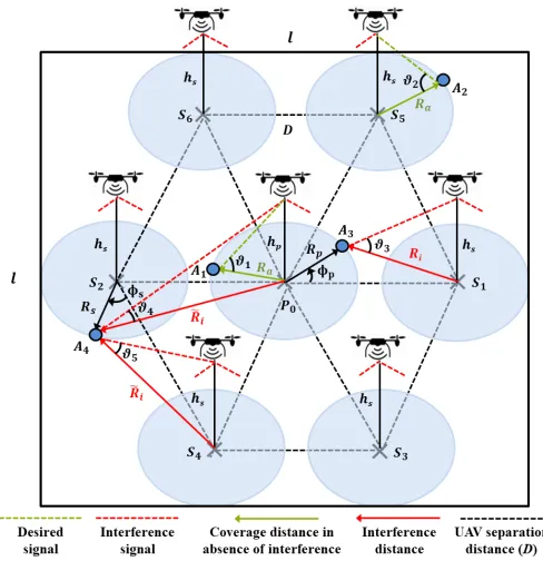
general multiple UAV model forM aerial base stations, this work assumes that the primary UAV is static and fixed on top of the center of a specified target area to serve as a reference node to adjust the separation distance, while secondary UAVs are placed at the predefined deployment coordinates. The secondary UAVs in this work are static after optimization so that the coverage is also static on the ground. Fig. 1 depicts a downlink UAV transmission system that consists of the primary UAV and secondary UAVs positioned at an altitude ofhpandhsmeters, respectively. Without loss of generality,
a two-dimensional (2D) Cartesian system is considered in which seven UAVs are used in the Euclidean plane of the square target area with a side length oflmeters and assume hexagonal layout for UAV deployment. It should be noted that the use of seven UAVs in Fig. 1 is only for illustration purpose. The model is applicable to any numbers of UAVs but in practice, large numbers are highly unlikely due to the exponentially increasing complexity for UAV control, such as collision avoidance and ground coordination. In this case,P0
is the projection center of the primary UAV and S1,···,M−1
are the coordinates of secondary UAVs located at the vertices, where M = 7 in Fig. 1. As a result, spatial isolation be-tween interfering UAVs is possible with the same separation distanceD. Moreover, coordinated multi-UAV networks can be deployed based on the layout of regular convex polygons to meet the coverage requirement inside the specific target area with the required number of UAVs. The advantage of such coordinated scheme is that it can react to failure of any UAVs quickly by reformation of the deployment strategy to the nearest regular polygon layout. The considered multi-UAV network offers resiliency of wireless network in case of malfunctioning base stations and providing coverage in post-disaster areas.
In the absence of interference, Ra is the maximum
cov-erage distance at the boundary points A1 and A2 in the
primary and secondary USC, respectively. In the presence of interference,Rp andRsare coverage distances that attain a
minimum performance, respectively, for boundary pointsA3
andA4 in the primary and secondary USC.Ri∈{1,···,M−1}
are distances to represent the worst-case scenario of the co-channel interference generated at the boundary of the primary USC from the projection of M −1secondary UAVs. Also,
e
Ri∈{1,···,M−1} denote the interference distances from the
boundary point of the serving secondary USC to the coor-dinates of all remaining UAVs in the network. The coverage performances of both the primary and secondary UAVs are dependent on Rp andRsas a function ofD for a specific
range of coverage angles, respectively,ΦpandΦs.
A. CHANNEL MODEL
FIGURE 1.Diagram of the multiple interfering UAVs scenario.
[8], [10], [16], [20], [22], and [32]. This model considers the effect of the environment with parameters αand β to characterize the AG propagation with the probability of LOS as
Px=
1
1 +α×e(αβ−βϑx), (1)
where x ∈ {1,2,3,4,5} represents elevation angles
ϑ1, ϑ2, ϑ3, ϑ4, and ϑ5 at boundary points in five scenarios
shown in Fig. 1. In the case of non-interfering link, the elevation angle for the primary UAV at point A1 is ϑ1 =
180
π arctan(
hp
Ra)and the mean path loss is given as [32]
Lp(dB) =A×P1+ 10 log10(h2p+R2a) +B. (2)
The elevation angle for secondary UAV at pointA2isϑ2= 180
π arctan(
hs
Ra)and the mean path loss is given as
Ls(dB) =A×P2+ 10 log10(h 2
s+R
2
a) +B. (3)
For the interference received in the primary USC at the boundary point A3 from secondary UAVs, ϑ3 =
180
π arctan(
hs
Ri)for i = {1,2,· · ·, M −1} and the mean
path loss is given as
Li(dB) =A×P3+ 10 log10(h2s+R2i) +B. (4)
For the interference incurred in the serving secondary USC at point A4 by the primary UAV, the interference distance
between projection coordinateP0and boundary pointA4is
e
Ri=1. Therefore,ϑ4= 180π arctan(
hp
e Ri=1
)and the mean path loss is given as
e
Li=1(dB) =A×P4+ 10 log10(h 2
p+Re2i=1) +B. (5)
For the interference received in the same secondary USC at point A4 from the remaining secondary UAVs, ϑ5 =
180
π arctan(
hs
e Ri
)fori={2,· · · , M−1}and the mean path loss is given as
e
Li(dB) =A×P5+ 10 log10(h 2
s+Re2i) +B. (6) whereA = ξLOS −ξN LOS,B = 20 log(4πfc ) +ξN LOS,
ξLOS and ξN LOS denote the excessive path loss factors
which rely on the propagation environment as well as on the LOS and NLOS conditions, respectively. Also, f is the carrier frequency andcis the speed of light.
The above channel model is considered due to its common-ality in the formulation of the optimization problem for UAV placement. In addition, the system parameters and channel characteristics are the same for all UAVs. Next, LsandLp
will be used to present SNR measures. Also,Li,Lei=1, and
e
Liwill be used for SINR metrics.
III. COVERAGE AREA PERFORMANCE OF COORDINATED MULTI-UAV NETWORK
Interference control is one of the major challenges in radio resource management of UAV communications. Intuitively, it is evident from the considered system model that, in the absence of coordination between UAVs, a large value ofD
separation distance between UAVs exists and provides trade-off between interference avoidance and maximum coverage. This section defines the deployment strategy for the consid-ered multi-UAV system and then employs it to present the coverage area performance and the coverage probability as a function of the UAV separation distance.
[image:5.576.308.540.583.663.2]A. UAV ALTITUDE
Fig. 2 illustrate the cases of symmetric and asymmetric deployments based on UAV altitude. In the symmetric case, the altitudes and transmit powers of all UAVs are identical. However, for asymmetric case, the primary UAV is placed at an optimal altitude and secondary UAVs can be located above or below this altitude. Therefore, the first goal of this work is to place the primary UAV at the optimal altitudehP
to achieve the maximum ground coverage in a specific target area for a given Ra. In this regard, the boundary point A1
on the ground is covered when its SNR is above a certain thresholdΨthfor a minimum transmit power,Ptp, i.e.
SN R(Ra, hp) =
Prp
N0
≥Ψth, (7)
where Prp = Ptp ×10
−Lp
10 is the received power in the
absence of interference,Lpis given in (2), andN0is the noise
power. The SNR for the secondary UAV is given as
SN R(Ra, hs) =
Prs
N0
≥Ψth, (8)
where Prs = Pts ×10
−Ls
10 is the received power in the
absence of interference, Pts is the corresponding transmit
power of secondary UAVs at altitudehs, andLsis given in
(3).
B. PROJECTION COORDINATES
This paper focuses on the use of quasi-stationary UAVs, where their positions remain unchanged for a specific du-ration of time. For such setup, it is important to determine the placement coordinates of UAVs to avoid collision be-tween them and to provide spatial isolation bebe-tween UAVs to control the interference. Therefore, the deployment strategy assumes that the primary UAV is fixed atP0={0,0}. When
M = 7, the coordinates of secondary UAVs in the hexagonal
layout are given as
S1,···,M−1=
S1 Dmin+D,0
S2 −(Dmin+D),0
S3 12(Dmin+D),−
√
3
2 (Dmin+D)
S4 −12(Dmin+D),−
√
3
2 (Dmin+D)
S5 12(Dmin+D),
√
3
2 (Dmin+D)
S6 −12(Dmin+D),
√
3
2 (Dmin+D)
,
(9) where Dmin=L4s−Rais the minimum separation distance
to avoid collision between UAVs and to ensure minimum coverage performance for all participating UAVs in the pres-ence of interferpres-ence. In this case,Dis the only variable which
controls the coverage area performance within a target area.
C. SIGNAL-TO-INTERFERENCE-PLUS-NOISE RATIO (SINR)
SINR is a commonly used metric for wireless communication systems to characterize the impact of interference generated by adjacent base stations. This affects the received signal strength at a ground user and consequently defines the cover-age area of the cell. This paper assumes that the participating UAVs in the considered system interfere with each other during the downlink transmission. In this case, a boundary user at pointA3is served by the primary UAV in the presence
of interfering secondary UAVs when its SINR satisfies the threshold requirementΨth. As a result, SINR can be defined
as
SIN R Rp(D),Φp=
Prp
I+N0
≥Ψth, (10)
whereRpis related to the interference distanceRias
Ri =
q
R2
p+D2+ 2RpDcos(π−Φp), (11)
and I = PtsPMi=1−110 −Li
10 is the co-channel interference
generated by secondary UAVs, andLiis given in (4).
For the boundary point A4 in the secondary USC, the
SINR is given as
SIN R Rs(D),Φs=
Prs
e
I+N0
≥Ψth, (12)
whereRsis dependent on the interference distanceReias
e
Ri=
p
R2
s+D2+ 2RsDcos(π−Φs), (13)
andIe=Ptp×10 −Lie=1
10 +PtsPM−1
i=2 10
−Lie
10 ,Lei=1is given
in (5), andLeiis given in (6).
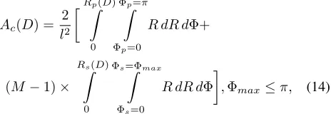
D. COVERAGE AREA PERFORMANCE AS A FUNCTION OF OPTIMAL SEPARATION DISTANCE
The coverage area ratio determines the overall coverage area performance of the considered multi-UAV system. Partic-ularly, it is defined as the ratio of the total effective area covered by both the primary and secondary USCs to the target area as
Ac(D) =
2
l2
Rp(D)
Z
0
Φp=π
Z
Φp=0
R dR dΦ+
(M −1)×
Rs(D)
Z
0
Φs=Φmax
Z
Φs=0
R dR dΦ
,Φmax≤π, (14)
where l2 is the area of the square target area considered
(a)hp=hs (b)hp< hs (c)hp> hs
FIGURE 2.Illustration of symmetric and asymmetric UAV deployment scenarios.
minimum coverage area ratio can be obtained atD=Dmin.
Also, Φmax limits the coverage of secondary UAVs that
might project outside the target area and is given as
Φmax=π−arccos
D
min+D
Rs
. (15)
Finally, the optimal separation distance can be computed by searching (14) numerically as
Dopt= arg max
D Ac(D). (16)
Analytical expressions for Dopt is difficult to obtain, if
not impossible. Therefore, this work will use simulation to study the effect ofD onAc(D)and to determine Doptfor
maximum coverage area ratio.
E. COVERAGE PROBABILITY OF THE BOUNDARY USER
The coverage probability is defined as
Pc=P[SIN R≥Ψth], (17)
which can be written as Pc = P[SIN R(D) ≥ Ψth] as
the SINR depends on the separation distance between UAVs and the thresholdΨthdetermined by the requirement of the
ground user. This performance metric quantifies the reliabil-ity of the AG channel in presence of co-channel interference by satisfying the threshold requirement. In addition, this met-ric is useful to evaluate the performance of the AG channel for command and control (CnC) in multi-UAV network [33]. A reliable CnC is crucial for safe UAV deployment and better traffic management in UAV communications.
For the proposed coordinated multi-UAV network, the shape of the coverage regions of the primary and secondary UAVs may not be completely circular in the presence of the co-channel interference. As a result, the coverage distances
Rp andRs varies non-uniformly for the primary and
sec-ondary USCs, respectively, as the value ofDchanges. In this case, the severe interference can be observed at the boundary points of USCs. The coverage probability for a boundary user located at the maximum distanceRpfrom the projection of
the primary UAV by considering the aggregate interference from all secondary UAVs is given as
Pc=P
P
rp
I+N0
≥Ψth
=P
Prp(dB)≥Pmin
. (18)
[image:6.576.300.530.170.455.2]whereP[.]denotes probability,Prpis the received power
TABLE 1.Simulation parameters.
Parameter Value
l 2000 meters
f 2 GHz
N0 -120 dBm
Ψth 10 dB
suburban (ξLOS,ξN LOS,α,β) 0.1 dB, 21 dB, 4.88, 0.43
urban (ξLOS,ξN LOS,α,β) 1 dB, 20 dB, 9.6, 0.28
10 300 600 900 1200 1500 -20
-18 -16 -14 -12 -10 -8 -6 -4 -2 0
Suburban Urban
FIGURE 3.UAV altitude versus transmit power for urban [16] and suburban environment withRa= 350meters.
in the absence of interference, Pmin = 10 log10(ΨthI +
ΨthN0) is the minimum received power (in dB) for
suc-cessful detection in presence of interference, and I can be extracted from (10). Similarly, the coverage probability can be determined for a ground user located at the maximum coverage distance Rs from the projection of the serving
secondary UAV by considering aggregate interference from remaining UAVs by using (12).
IV. NUMERICAL RESULTS AND DISCUSSION
In this section, numerical results are presented. Simulation parameters for suburban and urban environments are listed in Table I.
Fig. 3 shows the optimal altitude for the primary UAV using (7) to have the minimum transmit power in order to attain the coverage at the maximum radial distance of 350 meters and satisfy the threshold requirement of Ψth = 10
[image:6.576.320.508.305.449.2](a)Three interfering UAVs (b)Five interfering UAVs (c)Seven interfering UAVs
FIGURE 4.Coverage map for coordinated multi-UAV deployment for different numbers of UAVs in suburban environ-ments to attain minimum coverage.
[image:7.576.65.527.253.402.2](a)Three interfering UAVs (b)Five interfering UAVs (c)Seven interfering UAVs
FIGURE 5.Coverage map for coordinated multi-UAV deployment for different numbers of UAVs in suburban environ-ments to attain maximum coverage.
and the ground user with the minimum transmit power. This leads to the best communication performance in the absence of interference. Fig. 3 also shows that the optimal altitude and minimum transmit power depends on the propagation environment. For instance, the optimal altitude is 131 meters and 314 meters in suburban and urban scenarios, respectively. This result is important for the power minimization in plan-ning multi-UAV networks.
Fig. 4 and Fig. 5 show the ground coverage pattern in a specific target area with different numbers of UAVs for the minimum and the maximum coverage, respectively, in suburban environment with the threshold of Ψth = 10dB
and the optimal altitude of 131 meters for all UAVs. The projection coordinates of UAVs are marked by black ‘×’. Particularly, Fig. 4(a) and Fig. 5(a) present the coverage of three UAVs placed along a single axis in one-dimensional (1D) formation with the separation distance of 247 meters and 747 meters, respectively. Fig. 4(b) and Fig. 5(b) depicts the coverage region of five UAVs deployed in 2D formation with the separation distance of 247 meters and 847 meters, respectively. Fig. 4(c) and Fig. 5(c) shows the coverage area of seven UAVs deployed in 2D formation with the separa-tion distance of 247 meters and 847 meters, respectively.
Expressions (10) and (12) are used to achieve the SINR re-quirements at the ground points for the coverage of different UAVs deployed at coordinates specified by (9). These results, use 103 sample points for individual UAVs to test ground coverage requirement and the green patches represent the coverage area of USCs that achieve the threshold requirement in the presence of interference. In this case, the separation distance of 747 meters in 1D formation and 847 meters in 2D formation compensates the strong co-channel interference because the maximum coverage area of the primary UAV is optimally confined within the target area, while a small portion of the coverage region of secondary UAVs falls out-side the target area. Furthermore, as the gap between USCs increases beyond these separation distance, the coverage area of secondary UAVs further moves outside the target area which results in undesirable coverage leakage. On the other hand, the separation distance of 247 meters in both 1D and 2D formations can cause detrimental interference effect on the coverage performance as the effective coverage area shrinks because of overlapping.
400 600 800 1000 1200 1400 1600 1800 2000 0
0.1
0.2 Suburban
Urban
400 600 800 1000 1200 1400 1600 1800 2000 0
0.2 0.4
Suburban Urban
400 600 800 1000 1200 1400 1600 1800 2000 0
0.25 0.5
Suburban Urban
(a)hp=hs
400 600 800 1000 1200 1400 1600 1800 2000 0
0.1
0.2 Suburban
Urban
400 600 800 1000 1200 1400 1600 1800 2000 0
0.2 0.4
Suburban Urban
400 600 800 1000 1200 1400 1600 1800 2000 0
0.2 0.4
Suburban Urban
(b)hp< hs
400 600 800 1000 1200 1400 1600 1800 2000 0
0.1
0.2 Suburban
Urban
400 600 800 1000 1200 1400 1600 1800 2000 0
0.2 0.4
Suburban Urban
400 600 800 1000 1200 1400 1600 1800 2000 0
0.25 0.5
Suburban Urban
[image:8.576.51.533.64.205.2](c)hp> hs
FIGURE 6. Coverage area ratio versus separation distance for different numbers of UAVs in suburban and urban environments.
400 600 800 1000 1200 1400 1600 1800 2000 0
0.1 0.2 0.3 0.4 0.5 0.6
FIGURE 7. Coverage area ratio versus separation dis-tance for seven UAVs deployed in urban environment with different SINR threshold.
400 500 600 700 800 900 1000 0.44
0.445 0.45 0.455 0.46 0.465 0.47 0.475 0.48
3 UAVs 5 UAVs 7 UAVs
FIGURE 8. Boundary user coverage probability in the primary USC for the severe interference generated from secondary UAVs for different number of UAVs in urban environment.
distancesRpin (11) andRsin (13) for the considered
multi-UAV network and then apply them in (14)-(16) to observe the effect of the UAV separation distance on the coverage area
performance in suburban and urban environments. Clearly, to mitigate the interference and to improve the coverage performance with higher number of UAVs, the coverage regions of UAVs must be isolated with proper adjustment in the separation distance. One notices that the coverage ratio changes with the number of UAVs and the environmental conditions.
In Fig. 6(a), when using the optimal altitude i.e.hp =hs,
better coverage performance is observed with three UAVs for
D <350meters in comparison with five and seven UAVs due
to lessen co-channel interference. In contrast, for the case of
hp < hsin Fig. 6(b), the coverage performance degrades as
the altitude of secondary UAVs increased from the optimal value because of higher path-loss. For the case ofhp> hsin
Fig. 6(c), best coverage area ratio is observed forD < 500 meters. However, as the separation distance increased from 500 meters the coverage performance becomes sub-optimal in urban environment. In these results, the minimum cov-erage area ratio is consistent with D = 1250 meters and
D = 1500 meters for 1D and 2D formations, respectively,
[image:8.576.61.246.264.408.2]when the maximum coverage of primary USC is attained and secondary UAVs moved out of the target area. Furthermore, it is observed that to achieve the maximum coverage area ratio, the optimal separation distance is dependent on the deploy-ment formation of UAVs rather on the number of UAVs or environment. For instance, with three UAVs deployed in the 1D formation, the optimal separation distance is 747 meters. Whereas, for five and seven UAVs deployed in 2D formation, the optimal separation distance is 847 meters.
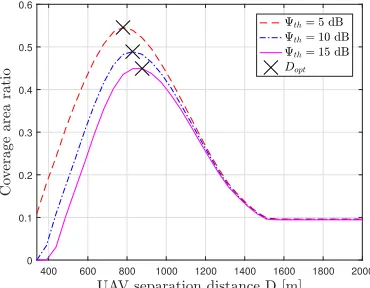
Fig.7 illustrate the impact of the SINR threshold on the coverage ratio and the optimal UAV separation distance in the urban environment for seven interfering UAVs. According to Fig. 7, the optimal UAV separation distance increases with the SINR threshold. For example Dopt = 780 meters for
Ψ = 5 dB, Dopt = 847 meters for Ψ = 10 dB, and
Dopt = 897 meters for Ψ = 15 dB. On the other hand,
[image:8.576.56.246.478.623.2]Fig. 8 shows that the coverage probability of the boundary user in the primary UAV cell in (18) with the threshold of Ψth = 10 dB. Fig 8. depicts that the user coverage
probability improves as the separation distance increases. In this case, the better user performance is possible in the worst-case scenario of the co-channel interference with the minimum required number of UAVs.
These results show that the aerial base stations can work similarly as the ground base stations with defined coverage patterns following principles of coordinated multi-point sys-tems for interference management [34]. This is important for the development of UAV base stations as a supplementary but flexible infrastructure to be compatible with existing fixed infrastructure.
V. CONCLUSION
The optimal separation distance between UAVs to mitigate co-channel interference and maximize the overall coverage performance has been studied in suburban and urban envi-ronments. For this, the coordinated multi-UAV network was designed that allowed us to provide the useful insights on the integration of multiple USCs in UAV communications. Results in this paper showed that the coverage area perfor-mance is dependent on the number of UAVs, operational environment, deployment coordinates or network formation, and separation distance between UAVs. In fact, a proper adjustment of the UAV separation distance can balance the co-channel interference to avoid coverage leakage outside the target area. This work could be extended for UAVs with different mobility laws and a multiple-tier UAV deployment to study the consequences of cross-tier interference in UAV communications. In this case, coverage performance by mul-tiple UAVs can be determined by multi-dimensional search for the optimal UAV altitudes and the separation distances.
REFERENCES
[1] Y. Zeng, R. Zhang, and T. J. Lim, “Wireless communications with un-manned aerial vehicles: Opportunities and challenges,"IEEE Commun. Mag., vol. 54, no. 5, pp. 36-42, May 2016.
[2] A. A. Khuwaja, Y. Chen, N. Zhao, M.-S. Alouini, and P. Dobbins, “A survey of channel modeling for UAV communications,"IEEE Commun. Surv. Tuts., vol. 20, no. 4, pp. 2804-2821, 4th Quart. 2018.
[3] A. Al-Hourani, S. Kandeepan, and S. Lardner, “Optimal LAP altitude for maximum coverage,"IEEE Wireless Commun. Lett., vol. 3, no. 6, pp. 569-572, Dec. 2014.
[4] A. Al-Houraniet al., “Coverage and rate analysis of aerial base stations," IEEE Trans. Aerosp. Electron. Syst., vol. 52, no. 6, pp. 3077-3081, Dec. 2016.
[5] M. Alzenad, A. El-Keyi, F. Lagum, and H. Yanikomeroglu, “3-D Place-ment of an unmanned aerial vehicle base station (UAV-BS) for energy-efficient maximal coverage,"IEEE Wireless Commun. Lett., vol. 6, no. 4, pp. 434-437, Aug. 2017.
[6] M. M. Azari, F. Rosas, K. C. Chen, and S. Pollin, “Optimal UAV position-ing for terrestrial-aerial communication in presence of fadposition-ing," inProc. IEEE GLOBECOM, Dec. 2016, pp. 1-7.
[7] Y. Chen, W. Feng, and G. Zheng, “Optimum placement of UAV as relays," IEEE Commun. Lett., vol. 22, no. 2, pp. 248-251, Feb. 2018.
[8] M. Alzenad, A. El-Keyi, and H. Yanikomeroglu. “3D placement of an unmanned aerial vehicle base station for maximum coverage of users with different QoS requirements,"IEEE Wireless Commun. Lett., vol. 7, no. 1, pp. 38-41, Feb. 2018.
[9] J. Lyu, Y. Zeng, R. Zhang, and T. J. Lim, “Placement optimization of UAV-mounted mobile base stations,"IEEE Commun. Lett., vol. 21, no. 3, pp. 604-607, Mar. 2017.
[10] R. I. Bor Yaliniz, A. El-Keyi, and H. Yanikomeroglu, “Efficient 3-D placement of an aerial base station in next generation cellular networks," inProc. IEEE ICC, May 2016, pp. 1-5.
[11] M. Mozaffari, W. Saad, M. Bennis, and M. Debbah, “Mobile internet of things: Can UAVs provide an energy-efficient mobile architecture?," in Proc. IEEE GLOBECOM, Dec. 2016, pp. 1-6.
[12] S. Kumar, S. Suman, and S. De, “Backhaul and delay-aware placement of UAV-enabled base station," inProc. IEEE INFOCOM Workshops, April 2018, pp. 634-639.
[13] M. Gruber, “Role of altitude when exploring optimal placement of UAV access points," inProc. IEEE WCNC, Sept. 2016, pp. 1-5.
[14] W. Feng, Y. Wang, D. Lin, N. Ge, J. Lu, and S. Li, “When mmWave communications meet network densification: A scalable interference co-ordination perspective,"IEEE J. Sel. Areas Commun., vol. 35, no. 7, pp. 1459-1471, Jul. 2017.
[15] S. Rohde and C. Wietfeld, “Interference aware positioning of aerial relays for cell overload and outage compensation," inProc. IEEE VTC-Spring, Sept. 2012, pp. 1-5.
[16] M. Mozaffari, W. Saad, M. Bennis, and M. Debbah, “Drone small cells in the clouds: Design, deployment and performance analysis," inProc. IEEE GLOBECOM, Dec. 2015, pp. 1-6.
[17] B. V. D. Bergh, A. Chiumento, and S. Pollin, “LTE in the sky: Trading off propagation benefits with interference costs of serial nodes,"IEEE Commun. Mag., vol. 54, no. 5, pp. 44-50, May 2016.
[18] I. Kovacs, R. Amorim, H. C. Nguyen, J. Wigard, and P. Mogensen, “Interference analysis for UAV connectivity over LTE using aerial radio measurements," inProc. IEEE VTC-Fall, Sept. 2017, pp. 1-6.
[19] D. G. Cileo, N. Sharma, and M. Magarini, “Coverage, capacity and interference analysis for an aerial base station in different environments," inProc. ISWCS, Aug. 2017, pp. 281-286.
[20] M. Mozaffari, W. Saad, M. Bennis, and M. Debbah, “Efficient deployment of multiple unmanned aerial vehicles for optimal wireless coverage,"IEEE Commun. Lett., vol. 20, no. 8, pp. 1647-1650, Aug. 2016.
[21] N. Zhaoet al., “Caching UAV assisted secure transmission in hyperdense networks based on interference alignment,"IEEE Trans. Commun., vol. 66, no. 5, pp. 2281-2294, May 2018.
[22] J. Sun and C. Masouros, “Deployment strategies of multiple aerial BSs for user coverage and power efficiency maximization,"IEEE Trans. Commun., vol. 67, no. 4, pp. 2981-2994, April 2019.
[23] Q. Wu, Y. Zeng, and R. Zhang, “Joint trajectory and communication design for multi-UAV enabled wireless networks,"IEEE Trans. Wireless Commun., vol. 17, no. 3, pp. 2109-2121, March 2018.
[24] F. Jiang and A. L. Swindlehurst, “Optimization of UAV heading for the ground-to-air uplink,"IEEE J. Sel. Areas Commun., vol. 30, no. 5, pp. 993-1005, June 2012.
[25] M. M. Azariet al., “Coverage maximization for a poisson field of drone cells," inProc. PIMRC, Oct. 2017, pp. 1-6.
[26] L. Liu, S. Zhang, and R. Zhang, “Cooperative interference cancellation for multi-beam UAV uplink communication: A DoF analysis," inProc. IEEE GLOBECOM, Dec. 2018, pp. 1-6.
[27] N. Zhao, X. Liu, F. R. Yu, M. Li, and V. C. M. Leung, “Communications, caching, and computing oriented small cell networks with interference alignment,"IEEE Commun. Mag., vol. 54, no. 9, pp. 29-35, Sep. 2016. [28] F. Cheng, Y. Yu, Z. Zhao, N. Zhao, Y. Chen, and H. Lin, “Power allocation
for cache-aided small-cell networks with limited backhaul,"IEEE Access, vol. 5, pp. 1272-1283, Jan. 2017.
[29] L. Liu, S. Zhang, and R. Zhang, “CoMP in the sky: UAV placement and movement optimization for multi-user communications," to appear in IEEE Trans. Commun., March 2019.
[30] U. Challita, W. Saad, and C. Bettstetter, “Interference management for cellular-connected UAVs: A deep reinforcement learning approach,"IEEE Trans. Wireless Commun., vol. 18, no. 4, pp. 2125-2140, April 2019. [31] W. Mei and R. Zhang, “Uplink cooperative NOMA for cellular-connected
UAV,"IEEE J. Sel. Areas Commun., vol. 13, no. 3, pp. 644-656, June 2019. [32] W. Feng, J. Wang, Y. Chen, X. Wang, N. Ge, and J. Lu, “UAV-aided MIMO communications for 5G Internet of Things,"IEEE Internet Things J., vol. 6, no. 2, pp. 1731-1740, April 2019.
[34] S. Sun, Q. Gao, Y. Ping, Y. Wang, and L. Song, “Interference management through CoMP in 3GPP LTE-advanced networks,"IEEE Wireless Com-mun., vol. 20, no. 1, pp. 59-66, Feb. 2013.
AZIZ A. KHUWAJAreceived his B.E. degree in telecommunication engineering from Mehran Uni-versity of Engineering & Technology, Jamshoro, Pakistan, in 2010 and M.Sc. in electronics com-munication and computer engineering from the University of Nottingham, U.K. in 2015. He is cur-rently pursuing Ph.D. in Engineering at the School of Engineering, the University of Warwick, U.K. He is also working as an Assistant Professor at the Department of Electrical Engineering, Sukkur IBA University, Sukkur, Pakistan. His research interests include wireless communications and radio resource management in UAV communications.
GAN ZHENG(S’05-M’09-SM’12) received the BEng and the MEng from Tianjin University, Tianjin, China, in 2002 and 2004, respectively, both in Electronic and Information Engineering, and the PhD degree in Electrical and Electronic Engineering from The University of Hong Kong in 2008. He is currently Reader of Signal Process-ing for Wireless Communications in the Wolfson School of Mechanical, Electrical and Manufactur-ing EngineerManufactur-ing, Loughborough University, UK. His research interests include machine learning for communications, UAV communications, edge caching, full-duplex radio, and wireless power trans-fer. He is the first recipient for the 2013 IEEE Signal Processing Letters Best Paper Award, and he also received 2015 GLOBECOM Best Paper Award, and 2018 IEEE Technical Committee on Green Communications & Computing Best Paper Award. He currently serves as an Associate Editor for IEEE Communications Letters.
YUNFEI CHEN (S’02-M’06-SM’10) received his B.E. and M.E. degrees in electronics engineer-ing from Shanghai Jiaotong University, Shanghai, P.R.China, in 1998 and 2001, respectively. He received his Ph.D. degree from the University of Alberta in 2006. He is currently working as an Associate Professor at the University of Warwick, U.K. His research interests include wireless com-munications, cognitive radios, wireless relaying and energy harvesting.