Study on Soft Storey Effect of Plan Regular and Irregular RC Framed
Structures under Different Seismic Zones using Response Spectrum
Method of Analysis
Aradhya B M S
1, Dr. B Shivakumara Swamy
21
Student M.Tech, Department of civil Engineering, Dr AIT, Bengaluru, Karnataka, India
2
Professor, Department of Civil Engineering, Dr AIT, Bengaluru, Karnataka, India
---***---Abstract -In urban India and modern world multi storey constructions open first storey is a typical common feature Due to the advantage of open space for the purpose of parking and for commercial use. And also plan irregularity structures has become common nowadays in urban areas for different reasons like non availability of required site dimensions, aesthetic view etc., Under high seismic regions the buildings built with open storey as well as irregular plan buildings are undesirable. This project aims for the study of performance of a Reinforced concrete frame building (G+13) with soft storey and with bare frame and also with masonry wall infill. Linear dynamic analysis (response spectrum analysis) is done using the software SAP2000 as per IS 1893-2002 ( part 1 ) and the results obtained from the structure like storey displacement, Storey drift, Base shear and time period were compared with the plan regular and irregular structures (re-entrant corner type of irregularity) under medium soil for seismic zones II & V.
Key Words: Soft storey, Response spectrum analysis,
SAP2000, Plan irregularity, Masonry wall infill.
1. INTRODUCTION
Due to past earthquake disasters we seen that many structures collapsed which were not designed as earthquake resistant structures and had huge destruction and also loss of life, so now this issue has become biggest challenge for civil and structural Engineers to make sure structures are safe during earthquake. In modern world plan irregularity structures has become common nowadays in urban areas for different reasons like non availability of required site dimensions, aesthetic view etc., irregularities as per IS code 1893-2002 are stiffness, diaphragm, out of offsets, no-parallel offsets, re-entrant corner, and torsion irregularity. Most buildings are outlined by irregular in each plan and vertical configuration.
Masonry infill generally includes of bricks or concrete blocks built between beams and columns of a reinforced concrete frame. The presence of masonry infill walls has an important impact on the seismic zone response of a reinforced concrete frame building, increasing structural strength a stiffness. The structural influence of infill wall results into stiffer structure thus decreasing the storey drifts. This improved overall performance makes the structural design greater practical to consider infill walls as
a structural element in the earthquake resistant design of structures.
1.1 Objectives
The objectives of this study are listed below.
To analyze the effect of soft storey in RC framed structure.
To study the behavior of the RC framed structure with soft storey and without soft storey.
To compare behaviour of RC framed plan regular and irregular structures under all seismic zones using response spectrum method.
To find the important parameters like Base shear, displacement, storey drifts and time period.
1.2 Methodology
Following method is adopted for the analysis,
1. Extensive literature review is carried out
2. Using the software SAP2000 analysis of the buildings with plan regular and irregularity is done, and also considered with and without soft storey as well as masonry infill.
3. Various parameters like Displacement, Storey drift, and Base shear and time period were obtained.
Based on the results obtained conclusions are derived.
2. MODEL DETAILS
Table -1: Description of models MODEL NUMBE R EART HQUA KE ZONE
PLAN TYPE STOREY DESCRIPTION
Model 1 ZONE
II Plan Regular Masonry wall in filled frame Model 2 ZONE
II Plan Regular Bare Frame (without masonry wall infill) Model 3 ZONE
II Plan Regular Soft Storey At Ground Floor frame Model 4 ZONE
II Plan Irregular Masonry wall in filled frame Model 5 ZONE
II Plan Irregular Bare Frame (without masonry wall infill) Model 6 ZONE
II Plan Irregular Soft Storey At Ground Floor frame Model 7 ZONE
V Plan Regular Masonry wall in filled frame Model 8 ZONE
V Plan Regular Bare Frame (without masonry wall infill) Model 9 ZONE
V Plan Regular Soft Storey At Ground Floor frame Model 10 ZONE
V Plan Irregular Masonry wall in filled frame Model 11 ZONE
V Plan Irregular Bare Frame (without masonry wall infill) Model 12 ZONE
V Plan Irregular Soft Storey At Ground Floor frame
2.1 Model dimensions
Building dimension X=30m, Y=30m,
Height of the building Z=53m (Including head room)
Number of stories = G+13
Each Storey height = 3.5m, 2m (Head Room)
Column spacing along X direction = 5 m
Column spacing along Y direction = 10 m
2.2 Material properties
Concrete Grades = M25, M30, M35 (As per IS standards)
Steel Grade = Fe500
2.3 Member properties
Slab thickness = 200mm
Wall thickness (outer) = 230mm (Masonry)
Parapet and partition walls = 115mm (Masonry)
Beam size = 230X350mm (M25), 250X850mm (M25)
Column size
= 350X350mm (M30), 500X1000mm (M30), [up to 26.5m]
= 300X300mm (M30), 350X700mm (M30), [26.5m to 53m]
Height of parapet wall =1.0m
2.4 General loading
Wall (230mm) load on beam = 12kN/m
Wall (115mm) load on beam = 6kN/m
Floor finish = 1kN/m2
Water tank load (circular 1.1m dia) = 12 kN/m2
Lift load considered on slab = 12 kN/m2
Live load (IS 875-1987 part 2) = 4kN/m2 (floor)
Live load (IS 875-1987 part 2) = 1.5kN/m2 (roof)
For seismic Zone II
Importance factor = 1.0 Response reduction factor =5 Site type = Medium (II) Zone Factor =0.10
For seismic Zone V
Importance factor =1.0 Response reduction factor= 5 Site type = Medium (II) Zone Factor =0.36
2.5 Planning and modelling
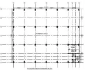
Before modelling, architectural plan of all the models are prepared using AutoCADD software.
[image:2.595.349.521.571.712.2]Fig -2: Regular plan 1 to 13 floors
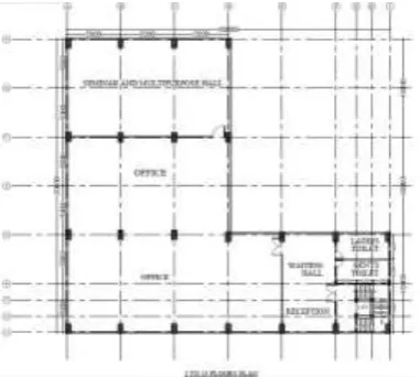
Fig -3: Irregular plan for ground floor
[Re-entrant corner type irregular building having projections 50% along X direction and 33.33% along Y direction]
Fig -4: Irregular plan for 1 to 13 floors
[Re-entrant corner type irregular building having projections 50% along X direction and 33.33% along Y direction]
Fig -5: Plan regular frame Fig -6: Plan regular
with masonry wall in fill bare frame
Fig -7: Plan regular frame Fig -8: Plan irregular frame
with Soft storey at GF masonry wall in fill
Fig -9: Plan irregular Fig -10: Plan irregular frame
Bare frame with soft storey at GF
3. ANALYSIS
[image:3.595.53.545.59.650.2] [image:3.595.63.262.318.503.2] [image:3.595.67.258.580.751.2]4 RESULTS AND DISCUSSIONS
The various parameters like Displacement, Storey drift, Base shear and Time period are obtained by carrying response spectrum analysis for the different models considered in this study.
[image:4.595.307.561.180.386.2]4.1 Displacement:
Fig -11: Displacement along X direction at zone II
[image:4.595.37.284.196.434.2]Fig-11 Shows the plots of displacement of structure along the height in X direction for model 1 to model 6, obtained by dynamic analysis for zone II. Model 2 has higher displacement compare to other models. The highest displacement of the building found to be 17.32mm in Model 2 (Regular plan with bare frame)
Fig -12: Displacement along X direction at zone V
Fig-12 Shows the plots of displacement of building along height in X direction for model 7 to model 12, obtained by dynamic analysis for zone V. Model 8 has highest displacement compare to other models. The maximum displacement of the building found to be 61.77mm in Model 8 (Regular plan with bare frame)
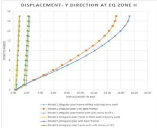
Fig -13: Displacement along Y direction at zone II
[image:4.595.299.560.496.718.2]Fig-13 Shows the plots of displacement of building along height in Y direction for model 1 to model 6, obtained by dynamic analysis for zone II. Model 5 has highest displacement compare to other models. The maximum displacement of the building found to be 17.32mm in Model 5 (Irregular plan with bare frame)
[image:4.595.42.564.499.752.2]Fig-14 Shows the plots of displacement of building along height in Y direction for model 7 to model 12, obtained by dynamic analysis for zone V. Model 11 has greater displacement compare to other models. The highest displacement of the building found to be 79.90mm in Model 11 (Irregular plan with bare frame)
[image:5.595.329.535.180.397.2]4.2 Storey Drift:
Fig -15: Storey drift along X direction at zone II
[image:5.595.42.280.197.407.2]Fig-15 Shows the plot of storey number v/s storey drift for model 1 to model 6, and observed that the storey drift is highest in the storeys where the soft storey is located. The highest value of storey drift in the X direction 0.0056m is occurred in the model3 (Regular plan frame with soft storey at GF) located in seismic zone II.
Fig -16: Storey drift along X direction at zone V
[image:5.595.324.541.511.732.2]Fig-16 shows the plot of storey number v/s storey drift graph for model 7 to model 12, it is observed that storey drift is highest in the storeys where the soft storey is situated. The highest value of storey drift in the X direction 0.0203m is occurred in the model9 (Regular plan frame with soft storey at GF) located in seismic zone V.
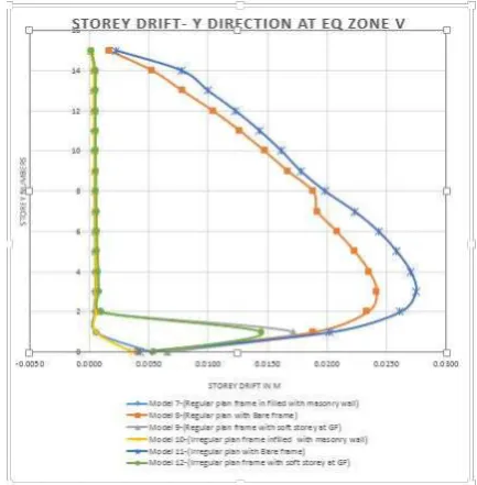
Fig -17: Storey drift along Y direction at zone II
Fig-17 Shows the plot of storey number v/s storey drift graph for model 1 to model 6, it is observed that the storey drift is maximum in the storeys where the there is no masonry wall infill is present. The maximum value of storey drift in the Y direction 0.0059m is occurred in the model 5 (Irregular plan with Bare frame) located in seismic zone II.
[image:5.595.43.276.518.742.2]Fig-18 shows the plot of storey number v/s storey drift graph for model 1 to model 6, it is observed that the storey drift is maximum in the storeys where the there is no masonry wall infill is present. The maximum value of storey drift in the Y direction 0.0275m is occurred in the model 11 (Irregular plan with Bare frame) located in seismic zone V
[image:6.595.37.288.198.277.2]4.3 Base shear:
Fig -19: Maximum base shear along X direction at zone II
[image:6.595.307.571.202.340.2]Fig-19 Shows the plot between maximum base shear v/s various models considered in the analysis. It is observed that the highest base shear value 4267.05 kN is occurred in the model 1 (Regular plan frame in filled with masonry wall) along the X direction located in seismic zone II. It is also observed that, masonry in fill influences the base shear of the building and model 1 which is in filled with masonry wall has higher base shear compared to other models.
Fig -20: Maximum base shear along X direction at zone V
Fig-20 Shows the plot between maximum base shear v/s various models considered in the analysis. In this observed that the highest base shear value 15094.74 kN is occurred in the model 7 (Regular plan frame in filled with masonry wall) along the X direction located in seismic zone V. And also observed that, models with bare frame has very less base shear compare to other models
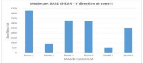
Fig -21: Maximum base shear along Y direction at zone II
[image:6.595.41.282.413.520.2]Fig-21 Shows the plot between maximum base shear v/s various models considered in the analysis. It is observed that the maximum base shear value 4266.95 kN is occurred in the model 1 (Regular plan frame in filled with masonry wall) along the Y direction located in seismic zone II. It is also observed that, masonry in fill influences the base shear of the building and model 1 which is in filled with masonry wall has higher base shear compared to other models.
Fig -22: Maximum base shear along Y direction at zone V
Fig-22 Shows the plot between highest base shear v/s various models considered in the analysis. In this observed that the maximum base shear value 15093.72 kN is occurred in the model 7 (Regular plan frame in filled with masonry wall) along the Y direction located in seismic zone V. And also observed that, models with bare frame has very less base shear compare to other models.
4.4 Time period:
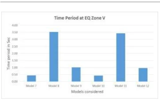
Fig -23: Maximum Time period at zone II
[image:6.595.308.568.478.624.2] [image:6.595.37.286.645.755.2]Fig -24: Maximum Time period at zone V
Fig-24 Shows the plot between time period v/s various models considered in the analysis. In this observed that the highest time period value 3.53 seconds is occurred in the model 8 (Regular plan with Bare frame) located in seismic zone V. It is also observed that models with masonry wall infill has very less time period compare to other models
5. CONCLUSIONS
From this study following conclusions are drawn:
Models having bare frame shows the maximum value of displacement in Both X and Y direction and under both Earthquake zones II and V compare to all other models because of less lateral stiffness of the storey.
The displacement value is considerably reduced in the models with masonry wall infill in both X and Y direction under seismic forces at both Earthquake zones II and V. from this we can conclude that we should prefer masonry wall infill instead of bare frame structures under higher seismic zones.
Models with soft storey shows higher value of storey drift than models without soft storey, therefore we should avoid soft storey in the buildings under higher seismic zones or we should increase the lateral stiffness of the storey by providing shear wall, bracings etc. The existence of masonry infill impacts the overall
behaviour of structures when exposed to earthquake forces. Lateral displacements and storey drifts are noticeably reduced when the involvement of the infill brick wall is taken into account
Models with bare frame shows very less base shear compare to models with masonry wall infill therefore we conclude masonry wall influences the base shear of the building.
Models with bare frame shows high time period compare to other models, which indicates bare frame buildings are more flexible under seismic forces. Models with masonry wall infill has very less time
period compare to other models which shows masonry infill makes building more stiffer and less flexible under seismic forces.
Re-entrant type of plan irregularity buildings having projections less than 50 % are acceptable under both
seismic zones II and V with masonry infill and not acceptable with bare frame .
When Column dimensions to be changed along the height of the building in bare frame buildings (considering economy point as well as requirements), sudden change of column dimensions with large difference should not be done which may lead to sudden storey drift.
Steel framed structure can be used to Study on soft storey effect of plan regular and irregular structures under different Seismic zones using response spectrum method of analysis can be done.
Buildings can be analyzed in different soil types and seismic zones III and IV also.
Other forms of irregularities as per IS 1893 (part1): 2002 such as Torsion irregularity, diaphragm discontinuity, out-of-plane offsets, non-parallel systems can be taken for further study
REFERENCES
[1] Singh Shailendra and Vasaikar Hemant Babulal, “Seismic
Response of Soft Storey on High Rise Building Frame”, www.ijetcr.org Volume 3; Issue 4; July-August-2015; ISSN: 2348 – 2117.
[2] K. Vamshi Satyanarayana and Vinod Kumar, “Seismic
Response of RC Frame Building with Soft Storey at Different Floor Levels”, www.ijettjournal.org – Volume-42 Number-4 - December 2016.
[3] S.Arunkumar and Dr. G. Nadini Devi, “seismic demand
study of soft storey building and it’s strengthening for seismic resistance”,www.ijettcs.org, ISSN 2278-6856, Volume 5,Issue 2, March - April 2016.
[4] Pavithra R and Vasaikar Hemant Babulal, “Study of
Behavior of the Soft Stories at Different Locations in the Multi-Story Building”,www.ijert.org, ISSN: 2278-0181, Vol. 7 Issue 06, June-2018.
[5] Deekshitha Y.L and Kiran Kuldeep K.N, “study linear and
non-linear dynamic analysis of multi storied R.C frame buildings with plan and vertical irregularities using ETABS”,www.irjet.net, p-ISSN: 2395-0072, Volume: 05 Issue: 07 | July 2018.
[6] Ganesh Kumbhar and Anirudhha Banhatti, “Seismic
Retrofitting of Building with Soft Storey and Floating Column”. www.irjet.net, ISSN: 2395-0072, Volume: 03 Issue: 07 | July-2016.
[7] Vihar S Desai, Hitesh K Dhameliya, Yati R Tank,
“investigate performance of a building with soft storey at different level along with ground level”, www.ijert.org, ISSN: 2278-0181, Vol. 6 Issue 04, April-2017.
[8] Pritam C. Pawade, Dr P.P Saklecha and Milind R Nikhar,
“Comparison and analysis of regular and irregular configuration of multistorey building in various seismic zones and various type of soil”, IARJSET, ISSN (Print) 2394-1588, Vol. 5, Issue 6, June 2018.
[9] V Rajendra Kumar and Ranga Rao V, “comparative study
on regular & irregular structures using equivalent static
and response spectrum methods”,
www.iaeme.com/IJCIET. ISSN Online: 0976-6316, Volume 8, Issue 1, January 2017.
[11] IS: 1893 (Part 1):2002 Criteria for earthquake resistant
design of structures.
[12] IS: 456-2000 plain and reinforced concrete code of
practice.IS: 875-1987 (part 1 to part 5) Code of Practice for Design Loads.
And more.
[10]Albert Philip and Dr. S. Elavenil , “Seismic analysis of