1
Interface Formation and Mn Segregation of Directly Assembled La0.8Sr0.2MnO3
Cathode on Y2O3-ZrO2 and Gd2O3-CeO2 Electrolytes of Solid Oxide Fuel Cells
Shuai He,a,b Kongfa Chen,c Martin Saunders,d Zakaria Quadir,e Shanwen Tao,f John T.S.
Irvine,g C. Q. Cui,a,* and San Ping Jianga,b,h*
aSchool of Electromechanical Engineering, Guangdong University of Technology,
Guangzhou 51006, People’s Republic of China
b Fuels and Energy Technology Institute & Western Australian School of Mines: Minerals,
Energy and Chemical Engineering, Curtin University, Perth, WA 6102, Australia
c College of Materials Science and Engineering, Fuzhou University, Fuzhou 350108, China d Centre for Microscopy, Characterisation and Analysis, The University of Western Australia,
Perth, WA 6009, Australia
e Microscopy and Microanalysis Facility, John de Laeter Centre, Curtin University, Perth,
WA 6102, Australia
f Department of Chemical Engineering, Monash University, Clayton, Victoria 3800, Australia g School of Chemistry, University of St Andrews, Fife KY16 9ST, UK
h Faculty of Science, Health, Education and Engineering, University of Sunshine Coast,
Maroochydore DC, Queensland 4558, Australia
Corresponding Author: [email protected] (CQ Cui); [email protected] (SP Jiang)
Abstract:
The establishment of intimate electrode/electrolyte interface is very important in solid oxide
fuel cells (SOFCs), because it plays a critical role in the overall cell performance and durability.
In this study, Mn segregation and interface formation between directly assembled
2
ceria (GDC) electrolytes are studied using combined focused ion beam and scanning
transmission electron microscopy (FIB-STEM). In the case of LSM/YSZ and LSM/GDC
electrodes, a significant reduction in the electrode ohmic resistance is observed after cathodic
polarization at 900oC and 500 mAcm-2, indicating the formation of an intimate interface.
However, LSM particles start to disintegrate at the electrode/electrolyte interface with the
increase of polarization time in the case of LSM/YSZ electrode. On the other hand, the
LSM/GDC interface is very stable with negligible microstructure change at the interface. Mn
segregation from the LSM perovskite structure is identified under the influence of polarization
in both LSM/YSZ and LSM/GDC electrodes. The results demonstrate that nature of the
electrolyte plays a critical role in the electrochemical activity, microstructure, morphology and
stability of LSM/electrolyte interface under SOFC operation conditions.
Keywords: solid oxide fuel cells; direct assembly; LSM cathodes; YSZ and GDC electrolyte;
interface; Mn segregation.
1. Introduction
Solid oxide fuel cells (SOFCs) are energy conversion devices to efficiently produce
electricity from chemical energy of a wide variety of fuels, such as hydrogen, natural gas and
hydrocarbons[1-5]. SOFCs are considered as environmentally friendly technologies with
significantly less greenhouse gas emission as compared to the coal combustion plants[6, 7].
Typical SOFC cells consist of Ni-yttria-stabilized zirconia (Ni-YSZ) cermet anodes, YSZ
electrolyte and lanthanum strontium manganite (LSM) perovskite cathode. Generally, the
ceramic components of the SOFC devices are pre-sintered at high temperatures, e.g., ~1400oC
for Ni-YSZ cermet anode and ~1150oC for LSM cathodes[8-10] to establish an intimate
3
electrocatalytic activity of electrode materials, but also the microstructure of the
electrode/electrolyte interface[11-14].
LSM perovskite is one of the most commonly and widely investigated cathode materials due
to its high electronic conductivity and excellent electrocatalytic activity for oxygen reduction
reaction (ORR) at high temperatures[10, 15, 16]. As LSM is predominantly an electronic
conductor with negligible ionic conductivity, the ORR mainly occur at the triple phase
boundary (TPB) where the oxygen, electrode and electrolyte meet. The formation of an
intimate electrode/electrolyte interface is thus critical in determining the performance and
durability of SOFC cells. This is because the interface provides a direct pathway for oxygen
species migration from electrode to electrolyte. In the case of LSM cathode pre-sintered at high
temperatures, the interface is characterized by the formation of convex contact rings on YSZ
and GDC electrolyte surface[14, 17-22]. On the other hand, it has been known that cathodic
polarization has a significant effect on the electrode/electrolyte interface under the fuel cell
operation conditions. This is reflected from the formation of micro-pores and dense layers at
the interface[19, 23-25], the increase in TPB length[26] and the change in electrolyte
morphology[21, 27]. Early studies show that polarization can broaden and flatten the edges of
the contact rings[18]. The distinct topography change of the convex contact rings is most likely
due to the incorporation of oxygen and/or interdiffusion between LSM and YSZ electrolyte at
the interface. The microstructural change at the electrode/electrolyte interface during long-term
cathodic polarization can also lead to a significant cell performance degradation. Appel et
al.[24] reported that after polarization at 300 mAcm-2 and 1000 oC for 2000 h, the overpotential
of a LSM-YSZ composite cathode based cell exceeds by 100% of the initial value. The
morphology changes at the interface due to pore formation and densification of the electrode
layer were considered as the main reasons for the increase in the polarization resistance during
4
Recently, we have shown the feasibility of applying directly assembled electrode on
electrolyte without requiring further high temperature sintering, and the in situ formation of
electrode/electrolyte interface induced by cathodic polarization[28-37]. In the case of LSM
electrode and YSZ electrolyte (LSM/YSZ), the results indicate that the electrochemical
performance of the cathodic polarization induced interface is comparable to that of the
conventional pre-sintered electrodes, though the topography of the interface is very different,
i.e. the formation of convex contact rings for the thermally induced interface and contact
clusters for the electrochemically induced interface[28]. The formation of the
electrochemically induced LSM/YSZ interface is accompanied by the pronounced decrease of
electrode ohmic resistance, particularly at the initial stage of polarization[31]. Studies show
that LSM is thermally compatible with YSZ and GDC electrolytes and the formation of
lanthanum zirconate only occurs at a higher temperature of 1300 oC in the case of LSM/YSZ
but in the case of LSM/GDC, no interfacial reaction was observed[22]. However, the evolution
of the electrode/electrolyte interface under the influence of cathodic polarization as well as the
fundamental understanding of the crystallographic and compositional changes of the
polarization induced interface in the case of directly assembled LSM electrodes are still unclear
at this stage.
In this paper, a comparative study was carried out on the electrochemical activity, interface
formation and Mn segregation of the directly assembled LSM electrode on YSZ or GDC
electrolytes using combined FIB-STEM technique. The results indicate that the
electrochemical performance of directly assembled LSM/YSZ and LSM/GDC electrodes is
greatly enhanced by the cathodic polarization. The electrode/electrolyte hetero-interface
formed under cathodic polarization is characterized by the periodic lattice plane matching,
5
shows a significant effect on the stability of the interface formed between LSM and YSZ or
GDC electrolyte.
2. Experimental
2.1. Fabrication of direct assembled LSM electrode on YSZ or GDC electrolyte
La0.8Sr0.2MnO3 (LSM) cathode powder was synthesized via sol-gel method, using
La(NO3)3·6H2O (99.9%, A.R., Alfa Aesar, UK), Sr(NO3)2 (99%, A.R., Sigma-Aldrich, US),
Mn(NO3)2 (50 wt% solution, A.R., Alfa Aesar, UK) as raw materials, and anhydrous citric acid
(99.5%, A.R., Chem Supply, Australia), ethylenediaminetetraacetic acid (EDTA, 99%, Acros
Organics, Australia) and ammonia solution (28%w.w., Sigma-Aldrich, US) as complexing
agents with a molar ratio of 1:1.5:1 (metal ions/citric acid/EDTA). Stoichiometric metal
nitrates were blended with deionized water, and the calculated amounts of citric acid, EDTA
and ammonia solution were subsequently added. The pH of the solution was adjusted to 7 and
the solution was stirred on a hot plate until the dry gel was formed. The resultant gel powder
was calcined at 1000oC for 2 h.
Electrolyte pellets were fabricated by die-pressing powders of 8 mol% Y2O3 doped ZrO2
(YSZ, Tosoh, Japan) and Gd0.1Ce0.9O1.95 (GDC, AGC Seimi Chemical Co Ltd), followed by
sintering at 1450oC for 5 h. The pellets were approximately 1 mm in thickness and 18 mm in
diameter. Pt paste (Gwent Electronic Materials Ltd., UK) was painted on the centre and ring
of the electrolyte, and sintered at 1100oC for 2 h as the counter and reference electrodes. LSM
powder was thoroughly mixed with an ink vehicle (Fuel Cell Materials, US) at a weight ratio
of 5:5 in an agate mortar to form a uniform electrode paste. The paste was subsequently
screen-printed on the other side of the electrolyte pellet symmetrically opposite to the Pt counter
electrode and then dried at 100oC for 2h to form the directly assembled cathode/electrolyte
6
2.2. Characterization
Electrochemical performance of directly assembled LSM/YSZ and LSM/GDC electrodes
was measured using a Zahner Electrochemical Workstation. The electrodes were cathodically
polarized at 750 oC and 500 mAcm-2 for 1 or 12 h, and electrochemical impedance was
measured under open circuit conditions in a frequency range of 0.1 Hz to 100 kHz with a signal
amplitude of 20 mV. Air was supplied to the cathode side at a flow rate of 100 mL min-1.
Electrode ohmic resistance (RΩ) was obtained from the high frequency intercept, and electrode
polarization resistance (Rp) was obtained from the differences between the low- and
high-frequency intercepts of the impedance curves.
The microstructure of the electrolyte surface in contact with LSM was examined by scanning
electron microscopy (SEM, Zeiss Neon 40EsB, Germany). In order to examine the morphology
of the electrolyte surface, the LSM coating was completely removed by HCl (32 wt%,
Sigma-Aldrich, US) treatment, and in some cases, the electrode was partly peeled off to study the
electrode/electrolyte interface. The topographic features of the acid cleaned electrolyte surface
were examined by atomic force microscopy (AFM, Alpha 300 SAR, WITec GmbH, Ulm
Germany) at intermittent contact mode. Electrolyte lamella in contact with LSM particle was
lifted out and milled to around 70 nm in thickness using FEI Helios Nanolab G3 CX Dual
Beam Focused Ion Beam - Scanning Electron Microscope (FIB-SEM, Helios Nanolab G3 CX,
FEI company, US) with Ga+ ion source. The elemental mapping and microstructural
micrographs were obtained on the FIB milled sample using a high angle annular dark field
scanning transmission electron microscopy (HAADF-STEM, FEI Titan G2 80-200
TEM/STEM with ChemiSTEM Technology, US) at 200 kV. The fast Fourier transform (FFT)
images were extracted using TEM Imaging & Analysis software (TIA, FEI Company, US) to
7
performed on Gatan Digital Micrograph (Gatan Digital Microscopy Suite, Gatan Inc., US) to
reconstruct the selected lattice planes using FFT images.
3. Results and Discussion
3.1 Electrochemical performance of directly assembled LSM/YSZ and LSM/GDC electrodes
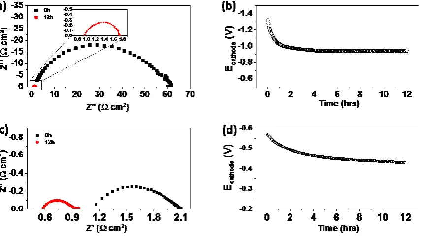
Fig. 1 shows the electrochemical performance of the directly assembled LSM cathode on
YSZ and GDC electrolytes after polarization at 900 oC and 500 mAcm-2 for 12 h. The
electrochemical activity of the LSM/YSZ electrode for ORR improves significantly with the
cathodic polarization. Rp was remarkably reduced from 60.0 Ω cm2 to 0.8 Ω cm2 and RΩ
decreased from 2.1 Ω cm2 to 0.9 Ω cm2 after polarization (Fig.1a). The cathode potential
measured between LSM electrode and Pt reference electrode (Ecathode) also dropped quickly
from its initial value of 1.3 V to ~0.9 V under the influence of cathodic polarization. For the
LSM/GDC electrode, the electrochemical performance also experiences a significant
improvement (see Fig. 1b). The initial RΩ and Rp were 1.1 Ω cm2 and 1.0 Ω cm2, respectively,
and decreased to 0.6 Ω cm2 and 0.3 Ω cm2 after polarization for 12 h. The E
cathode also decreases
gradually from 0.55V to 0.45V. The significantly enhanced activity is due to the well-known
activation behaviour of LSM-based cathode [10, 14, 39-44]. The significant decrease in the RΩ
for both LSM/YSZ and LSM/GDC electrodes implies the establishment of cathode/electrolyte
interface under the influence of cathodic polarization, as in the case of pre-sintered LSM/YSZ
and LSM/GDC electrodes, there is no change in RΩ under similar cathodic polarization
conditions [22, 31]. It is noted that Rp for ORR on LSM/GDC electrode is significantly smaller
than that on LSM/YSZ electrode under identical conditions (e.g., 1.0 Ω cm2 vs 60.0 Ω cm2 at
the initial polarization stage), indicating that the high ionic conductivity of GDC electrolyte
promotes the ORR on LSM electrode. This is consistent with the observed strong dependence
of the electrocatalytic activity of mixed ionic and electronic conducting cathodes for ORR on
8
3.2 Microstructure of the polarization induced interface
The microstructure of the YSZ and GDC electrolytes surface in contact with LSM cathode
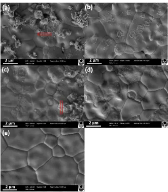
before and after polarization is presented in Fig. 2 and Fig. 3, respectively. For the LSM/YSZ
electrode, the morphology of the electrolyte surface was greatly changed after polarization at
900 oC and 500 mAcm-2 for just 1 h (Fig.2). Pure YSZ electrolyte surface without contact with
LSM coating was smooth and flat and grain size of YSZ was 3.77 3.12 μm (Fig. 2e). The
formation of ring-shaped contact marks was observed and the diameter of the contact marks
was in the range of 0.57-1.1 µm (Fig. 2b). The dimension of the ring-shaped contact marks is
close to that of the LSM particles of the directly assembled LSM, 1.27 0.54 µm (Fig.2a).
Within the contact rings, a considerable number of particles with a dimension of 28.8 8.4 nm
were found, indicating the possible disintegration of the LSM particles under the influence of
polarization. After the polarization for 12 h, the ring-shaped contact marks continue to grow
and merge together, forming contact craters with dimension as large as 2 µm on the YSZ
electrolyte (Fig. 2c and d). Matsui et al. also observed the significant microstructural change
at the interface between pre-sintered LSM electrode and YSZ electrolyte and the increase of
roughness of YSZ surface both in and out of contact with LSM particles with the increase of
the polarization time at 1000 oC [14]. An increase in the length of three phase boundary was
observed after polarization at 200 mA cm-2 for 5 h.
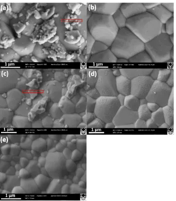
In the case of LSM/GDC electrode, the change in the morphology of GDC electrolyte is
much smaller during the cathodic polarization as compared to that on YSZ electrolyte (see Fig.
3). For instance, after polarization for 1 h, the morphology of the GDC electrolyte surface was
still smooth with a formation of small and shallow ring-shaped contact marks, as shown in Fig.
3a and b. After polarization for 12 h, the contact marks also grew in size (Fig. 3d), but no
ring-shaped contact marks were found as in the case of LSM/YSZ electrode (Fig.2d). The changes
9
polarization are much less significant as compared to that of YSZ electrolyte. The morphology
of pristine GDC electrolyte surface is also smooth with distribution of large and small GDC
grains (Fig.3e). The average grain size was 1.19 1.04 μm.
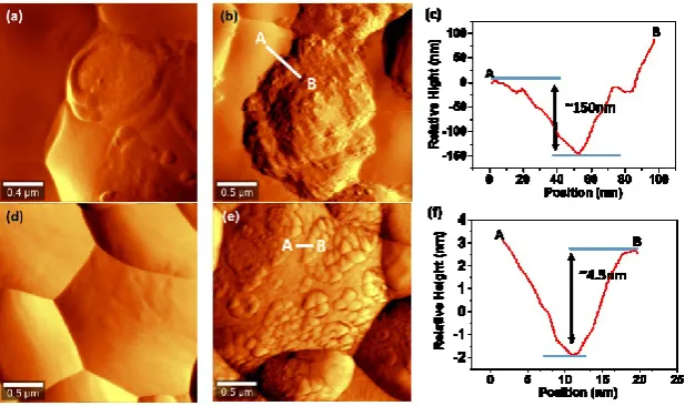
Fig. 4 shows the AFM topography of the YSZ and GDC electrolyte surfaces in contact with
LSM cathode. LSM electrodes were removed by acid treatment. In the case of LSM/YSZ
electrode, convex contact rings with a dimension of 1.14 0.54 µm was formed on the YSZ
surface after the cathodic polarization for 1 h (Fig. 4a). After polarization for 12 h, the contact
rings grew significantly, and the dimension of the rings increased to 1.800.71 µm (Fig.4b).
The AFM line scan across the edge of the contact rings revealed the ring depth profile of
0.140.06 µm (Fig.4c), showing the significant roughening of the YSZ electrolyte surface. For
the LSM/GDC electrode, the change in the electrolyte morphology is almost negligible after
polarization for 1 h (Fig. 4d). After polarization for 12 h, the formation of contact clusters or
marks on GDC electrolyte surface became clearly visible (Fig.4e). The average dimension of
these clusters was 0.220.09 µm with the depth profile of 5.20.7 nm (Fig.4f), substantially
smaller than that on YSZ electrolyte. The relatively small microstructure change of the GDC
electrolyte at the interface implies that the LSM cathode is more stable with GDC as compared
to that with YSZ under the influence of polarization, consistent with the thermal compatibility
studies[22].
Fig. 5 presents the LSM/YSZ and LSM/GDC interface lamella prepared by FIB, taking in
the interface regions as shown in Figs. 2 and 3. The TEM images of the electrode/electrolyte
interfaces clearly demonstrate the interface evolution under the influence of cathodic
polarization. For example, in the case of LSM/YSZ electrode, it appears that the LSM particle
started to disintegrate at the electrode/electrolyte interface after the polarization for 1 h,
10
disintegration of the LSM cathode particle at the interface became clearly visible (Fig. 5b). In
the case of LSM/GDC electrode, no visible disintegration of the LSM cathode particle was
observed. After polarization for 1 h, an intimate and void-free contact between LSM and GDC
electrolyte was established (Fig. 5c). The interface appears stable after polarization for 12 h
(Fig.5d), very different to the LSM/YSZ interface.
3.4 LSM/YSZ interface
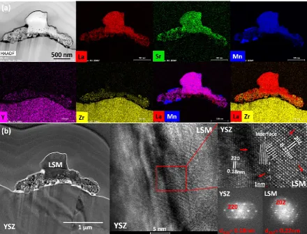
Fig. 6 shows the STEM-EDS and HRTEM results of a directly assembled LSM cathode on
YSZ electrolyte after polarization at 900 oC and 500 mAcm-2 for 1 h. There was a disintegration
at the interface and a clear presence of La, Sr and Mn was observed in the disintegrated
nanoparticles (Fig.6a). A strong accumulation of Mn was also observed on the surface of one
of the LSM particles, indicating the Mn segregation under the influence of cathodic
polarization. Nevertheless, the segregated Mn was not observed at the electrode/electrolyte
interface, indicating that segregated Mn species from LSM perovskite structure may not
migrate to the interface under the cathodic polarization conditions. The HRTEM analysis
shows an intimate contact between the LSM particle and YSZ electrolyte with lattice planes
meeting and matching at the interface. For example, the particle can be identified by the
periodic lattice arrangement of {202}LSM planes with a plane spacing of 0.22 nm[47, 48],
indicating that disintegrated particles exist as LSM perovskite phase. The YSZ electrolyte is
characterized by the {111}YSZ lattice planes with plane spacing of 0.29 nm[49]. In this instance
the orientation relationship, i.e., the angle between the {202}LSM and {111}YSZ lattice planes at
the interface, was found to be θ{202}LSM/{111}YSZ = 46.9o, and the mismatch factor (f) [50-53] for
these two planes can also be calculated:
𝑓 =𝑑{111}𝑌𝑆𝑍−𝑑 𝑑{202}𝐿𝑆𝑀
11
However, it should be noted that the current examined interface and the orientation relationship
between {202}LSM and {111}YSZ lattice planes may be different at different locations, as a result
of the polycrystalline nature of both phases. The establishment of the interface between
disintegrated LSM particles and YSZ electrolyte is supported by the significant decrease in RΩ.
The disintegration of LSM cathode particle at the electrode/electrolyte interface is
significant after polarization at 900oC and 500 mAcm-2 for 12 h, as shown in Fig. 7. The portion
of the LSM particle in contact with YSZ electrolyte decomposed into a large number of small
particles with the formation of voids in the bulk, and Mn segregation was also observed. In the
disintegrated LSM particles, there is a presence of Zr and Y in addition to La, Sr and Mn,
implying the interaction and formation of La-Mn-Zr solid solution[54-57]. Although the
formation of La2Zr2O7 cannot be ruled out at this stage, the continuous decrease of RΩ during
the polarization may indicate that the presence of such solid solutions between LSM and YSZ
on the ORR is negligible and insignificant[58]. The atomic geometry of the hetero-interface
between the YSZ electrolyte and the disintegrated LSM particles shows the lattice plane
matching of the LSM and YSZ phases at the interface, i.e., YSZ phase with {220}YSZ planes
and plane spacing of 0.18 nm and LSM with {202}LSM planes and plane spacing of 0.22 nm
(Fig. 7b). The orientation relationship between the two examined planes was found to be
θ{202}LSM/{220}YSZ = 50.0owith a lattice mismatch factor of f =18.2%. The FFT diffractogram of
the electrolyte shows a typical cubic YSZ structure[49, 59], while for the LSM phase, it appears
to be an overlap of two sets of same patterns at different orientation. This clearly indicates the
overlap of two disintegrated LSM particles. Also, the abrupt image contrast change at the
LSM/YSZ interface is most likely due to the strain effect resulted from the lattice mismatch of
the heterogeneous phases[60-63]. The mismatch strain and the lattice misfit are usually relaxed
and accommodated by the occurrence of misfit dislocations [64-66], e.g. lattice plane distortion
12
3.5 LSM/GDC interface
The influence of cathodic polarization on the interface of directly assembled LSM/GDC
electrodes was also investigated and the results are shown in Fig.8. Different to that observed
on the LSM/YSZ electrode, no Mn segregation was observed after polarization at 900 oC and
500 mAcm-2 for 1 h (Fig. 8a). An intimate LSM/GDC interface was established with a high
level of periodicity and symmetry, free of voids and amorphous phases (Fig.8b). The GDC
electrolyte is characterized by {111}GDC planes with plane spacing of 0.31 nm, while LSM
cathode can be identified by {110}LSM lattice planes with plane spacing of 0.27 nm. The
orientation relationship of these two planes was θ{111}GDC/{110}LSM = 11.0o with f = 12.9%.
Similar to the LSM/YSZ interface, the lattice plane distortion was also observed (indicated by
the red arrows in Fig. 8b). Nevertheless, the observed lattice distortion only existed locally at
the interface region without propagating into the electrode or electrolyte bulk.
The directly assembled LSM on GDC electrolyte was also polarized at 900 oC and 500
mAcm-2 for 12 h. LSM particles were in good contact with GDC electrolyte and there was no
disintegration of LSM phase at the interface (Fig.9a), very different to that observed on
LSM/YSZ electrode under the identical polarization conditions (Fig.7). However, similar to
LSM/YSZ electrodes, Mn segregation from the LSM perovskite was observed. The
polarization induced LSM/GDC interface is sharp and characterized by a high symmetry of
lattice plane structure for both LSM and GDC phases (see Fig. 9b). From the FFT diffractogram
images, the GDC electrolyte phase can be identified by its {220}GDC lattice planes with plane
spacing of 0.19 nm, while LSM phase by the {012}LSM and {024}LSM planes with plane spacing
of 0.39 nm and 0.19 nm, respectively. The orientation relationship of {220}GDC and {024}LSM
was found to be 14.7o with lattice mismatch factor of 13%. The much stable LSM/GDC
interface may indicate that the solubility of La3+ and Mn2+ in GDC is much lower than that in
13
Mn segregation from the LSM perovskite structure occurs in both LSM/YSZ and LSM/GDC
electrodes under SOFC polarization conditions. Fig.10 presents typical STEM-EDS element
mapping and HRTEM analysis of the interface between segregated manganese oxide (MnOx)
and LSM electrode on GDC electrolyte after polarization at 900 oC and 500 mAcm-2 for 12 h.
The segregation of MnOx was indicated by the {013}MnOx and {111}MnOx planes with
corresponding lattice plane spacing of 0.29 nm and 0.25 nm, respectively (Fig.10b). The MnOx
particle is in an intimate contact with LSM electrode, free of voids or other phases,
characterized by a high level of symmetry and periodicity in lattice plane arrangement at the
interface. The interface geometry of MnOx/LSM was revealed as the matching of {111}MnOx
and {110}LSM lattice planes with an orientation relationship of θ{111}MnOx/{110}LSM = 40.7o and a
mismatch factor of 7.4%. The influence of Mn segregation on the performance degradation of
the LSM/YSZ and LSM/GDC cells is not clear at this stage. However, MnOx has a low
electronic conductivity. The segregated MnOx, if diffuses at the TPB, would partially block the
transfer of electrons thus the increase of contact resistance might be expected, which would
lead to the degradation of LSM electrode.
3.6 Effect of polarization on the interface formation and Mn segregation
The results shown in the present study clearly indicate the significant effect of cathodic
polarization on the interface formation and Mn segregation of directly assembled LSM/YSZ
and LSM/GDC electrodes. The findings on the cathode/electrolyte interface microstructure and
Mn segregation is summarized below:
1. For directly assembled LSM/YSZ electrode, there is a significant change in the
microstructure and morphology of the YSZ electrolyte surface in contact with LSM
electrode, indicated by the disintegration of LSM particles and formation of ring-shaped
14
size, and the disintegration of the LSM particle becomes much more obvious at the
interface, resulting in the formation of La-Mn-Zr solid solution. The results indicate the
establishment of an intimate interface and the atomic geometry of the LSM/YSZ
interface is characterized by the matching of {202}LSM and {111}YSZ or {220}YSZ lattice
planes with a mismatch factor of 18.2-24.1%. The significantly enhanced
electrochemical performance with the cathodic polarization demonstrates that the
disintegrated LSM particles at the LSM/YSZ interface do not significantly impede the
oxygen reduction process.
2. In the case of directly assembled LSM/GDC electrode, the change in the microstructure
and morphology of GDC electrolyte is much smaller, very different from the substantial
microstructure changes observed for the LSM/YSZ electrodes under the identical
polarization conditions. Disintegration of LSM particles at the interface was not
observed. The polarization induced LSM/GDC interface is indicated by the formation of
small and shallow contact marks, and characterized by the matching of {024}LSM and
{220}GDC or {110}LSM and {111}GDC lattice planes with a mismatch factor in the range
of 1.3% to 12.9%. As compared to the LSM/YSZ electrode, the LSM/GDC interface is
quite stable under polarization conditions, which is in good agreement with that reported
in the literature[67]. Electrochemically, LSM/GDC electrode behaves similarly to that
of LSM/YSZ electrode, showing the significantly reduced polarization and ohmic
resistance with the polarization, though the magnitude in the change of the polarization
resistances is relatively smaller (see Fig.1).
3. The significantly enhanced electrochemical performance of LSM electrodes during the
cathodic polarization indicates that the presence of misfit dislocations and distortions at
the interface does not impede the migration and incorporation of O2- from the LSM
15
that reported in the literature [22, 37, 69]. For example, Pergolesi et al.[69] fabricated
CeO2 and YSZ biaxially textured epitaxial thin film using pulsed laser deposition method,
and found that the hetero-interfaces were not uniform but significantly strained, yet no
detectable contribution to the oxygen transport properties was found.
4. For both LSM/YSZ and LSM/GDC electrodes, Mn segregation from the cathode was
observed under the influence of the cathodic polarization. The segregated Mn particle
most likely exists as MnOx, and does not show preferential deposition at the interface,
indicating that the segregated Mn would not diffuse to the cathode/electrolyte interface
during the oxygen reduction process. The observed MnOx/LSM interface is sharp and
clean without any noticeable voids or amorphous phase. The atomic geometry of the
examined interface can be identified by the matching of {111}MnOx and {110}LSM lattice
planes with a mismatch factor of 7.4%.
Mn segregation has been commonly observed on the LSM electrodes under SOFC operation
conditions. Chen et al.[70] studied the interface reactions between LSM cathode and YSZ
electrolyte in different atmospheres at 1000 oC and found that Mn segregation was more
pronounced at low oxygen partial pressure. This is consistent with that reported by Nishiyama
[71], in which the oxygen potential gradient developed in the manganite was considered to give
rise to the similar gradients in chemical potential of manganese, providing a driving force for
manganese oxide segregation at the surface. Liu et al.[72] studied the influence of water vapour
on the degradation behaviour of LSM based cells and observed an enrichment of Mn2O3 and
Mn3O4 nano-particles (~100 nm in size) on the electrode surface by STEM-EDS mapping after
the cell was exposed to 20 vol.% humidified air and operated at 800 oC for 200 h. We also
observed a clear formation of Mn-rich phase, possibly Mn3O4 in the LSM electrode after the
16
Liu et al.[74] reported that Mn segregation occurred for the LSM-YSZ composite cathode
and YSZ electrolyte after polarization at 850 oC and 1.76 Acm-2 for 1500 h, and proposed that
the Mn migration cannot be simply attributed to the element diffusion. For perovskite-type
LSM, the electrical neutrality due to substitution of La3+ by Sr2+ at the A site is maintained by
a change in Mn valence. Lee et al. investigated active sites for O2 reduction in the LSM
electrode under various cathodic polarization potentials using in situ X-ray photoelectron
spectroscopy (XPS) and observed a shifting of the Mn 2p peaks to the lower binding energy
side as the applied potential became more cathodic[75]. A recent study by Traulsen et al.[76]
using operando X-ray absorption spectroscopy techniques showed that cathodic polarizations
induced a shift in the Mn K edge energy towards lower energies due to a decrease in the average
Mn oxidation state. This suggests the valence change of Mn ions in the lattice and interstitial
sites under cathodic polarization. The valence change of Mn ions in the perovskite can cause
the structural change and segregation of Mn species to the electrode and electrolyte surface[77,
78]. The segregation of Mn species under cathodic polarization conditions has also been
suggested as the main nucleation agents for the deposition of Cr on LSM electrodes under
SOFC operation conditions[79, 80].
The current study demonstrates that nature of electrolyte has a significant effect on the
stability of the LSM/electrolyte interface. LSM on GDC electrolyte shows a much more stable
interface than that of LSM on YSZ electrolyte under identical polarization conditions. Due to
the fact that the directly assembled electrodes do not go through the high temperature sintering,
the initial physical contact between LSM electrode with YSZ or GDC electrolyte is very weak.
Consequently, the low contact area would result in the initial high contact resistance (i.e., RΩ),
2.1 Ω cm2 in the case of LSM/YSZ electrode and 1.0 Ω cm2 in the case of LSM/GDC electrode.
The high ohmic resistance will result in a much higher local current density at the interface,
17
interface and thus enhance the contacts at the interface. This explains the significant reductions
in RΩ after polarization at 900 oC and 500 mAcm-2 for 12 h from 2.1 to 0.9 Ω cm2 on LSM/YSZ
electrode and from 1.0 Ω cm2 to 0.3 Ω cm2 on LSM/GDC electrode (Fig.1). However, the
observed disintegration of LSM particles at the LSM/YSZ interface indicates that the heat
generated at the LSM/YSZ interface would be significantly higher than that at the LSM/GDC
interface. The underlying reason for the differences in the localized heating at the interface is
most likely related to the significant differences in the ionic and electronic conducting
properties of YSZ and GDC materials. YSZ is a pure oxygen ion conductor with the ionic
conductivity in 0.08-0.11 S/cm range at 1000 oC [81, 82], while the doped ceria, such as GDC,
is a mixed ionic and electronic conductor with significantly higher conductivities (0.20-0.25
S/cm at 1000 oC) [83, 84]. The high ionic conductivity and mixed ionic and electronic
conducting properties of GDC could reduce the electrode ohmic resistance and at the same
time accelerate the oxygen migration and diffusion at the interface between LSM and GDC.
The electronic conductivity of GDC becomes significant at low oxygen partial pressure and
high operating temperature (>800oC) [85, 86], therefore the electronic current in GDC can
occur, which may also influence the reaction at the LSM/GDC interface. This is in fact
supported by the much lower RΩ and Rp values of the LSM/GDC electrode, as compared to that
measured on LSM/YSZ electrodes before polarization (see Fig.1).
Fig. 11 shows a schematic diagram to compare the Mn diffusion and interface formation in
pre-sintered[22] and directly assembled LSM/YSZ and LSM/GDC electrodes in this study. For
the pre-sintered LSM/YSZ cell, the interface establishment after high temperature sintering is
characterised by the formation of convex contact rings on the electrolyte, and the atomic
geometry of the intimate electrode/electrolyte interface can be identified by a high level of
symmetry, free of voids and amorphous phases (Fig.11a). In addition, Mn2+ and La3+ cation
18
observed, indicating a strong solubility of La3+ and in particular Mn2+ species in YSZ. Similar
to the LSM/YSZ electrodes, the pre-sintered LSM/GDC interface is also characterised by the
formation of convex contact rings on the GDC electrolyte surface. No cation diffusion is
detected due to their low solubility in doped ceria. This is in good agreement with the chemical
equilibrium calculations reported in the literature [87]. In (ZrO2)0.85(YO1.5)0.15 at 1000 oC, the
calculated solubility of manganese is 5.1 %, (1.4% as Mn3+ and 3.7% as Mn2+). A detailed
experimental investigation of the ternary phase diagram of (Zr,Y)O2-La2O3-Mn3O4 at 1400 oC
showed that the solubility of manganese in cubic zirconia solid solution phase was between 15
and 25 mol%[57]. In contrast, no solid solution was observed in MnO-Mn2O3-CeO2 system
above 800 oC. As the Mn segregation is most likely caused by the valence change of Mn ions
in the perovskite structure under cathodic polarization conditions[75, 76], this also explains the
observation that no MnOx segregation occurs on pre-sintered LSM/YSZ and LSM/GDC
electrodes (see Fig.11a)[22]. In the case of the directly assembled LSM/YSZ and LSM/GDC
electrodes, the formation of an intimate electrode/electrolyte interface was also observed under
the cathodic polarization conditions (Fig.11b). The significant differences in the microstructure
and morphology of the electrode/electrolyte interface can be attributed to the significant
differences in the nature of YSZ and GDC electrolyte materials as discussed above.
5. Conclusion
The interface formation and Mn segregation and diffusion of directly assembled LSM/YSZ
and LSM/GDC electrodes were studied under cathodic polarization conditions at 900 oC using
combined FIB-STEM techniques. The results indicate that in the case of both LSM/YSZ and
LSM/GDC electrodes, the cathodic current passage induces the formation of intimate
electrode/electrolyte interface, indicated by the significant reduction in both Rp and RΩ.
However, the change in the YSZ electrolyte surface in contact with LSM electrode is
19
phase at the electrode/electrolyte interface and the formation of ring-shaped contact craters at
the interface. The main reason for the disintegration of LSM phase at the interface is due to the
much higher localized heat generated at the interface due to the low ionic conductivity of YSZ
electrolyte material in comparison to that of GDC electrolyte. In addition, Mn segregation was
observed for both LSM/YSZ and LSM/GDC electrodes under the effect of cathodic
polarization, and the segregated MnOx does not show preferential deposition at the interface.
This is probably the main reason for the negligible detrimental effect of segregated MnOx on
the electrochemical activity of LSM electrode studied in this work. This study provides an
insight in the fundamental understanding of electrode/electrolyte interface formation and Mn
segregation in relation to the nature of electrolyte of SOFCs and has significant implications in
the development of active and stable cathodes of SOFCs in general.
Acknowledgment
This work was financially supported by the Australian Research Council under the
Discovery Project Scheme (project number: DP180100731 and DP180100568), and by the
Guangdong Provincial Department of Science and Technology Agency (GDST) under the
GDST-NOW Science-Industry Coorperation Program (No.2017A050501053). The authors
acknowledge the facilities and the scientific and technical assistance of Curtin University
Microscopy & Microanalysis Facility and the Australian Microscopy & Microanalysis
Research Facility at the Centre for Microscopy, Characterization & Analysis, The University
of Western Australia, a facility funded by the University, State and Commonwealth
Governments, and the Key Laboratory of Precision Microelectronic Manufacturing
Technology & Equipment of Ministry of Education of China.
References:
20
[2] A. Choudhury, H. Chandra, A. Arora, Renewable and Sustainable Energy Reviews 20 (2013) 430.
[3] K. Chen, L. Zhang, N. Ai, S. Zhang, Y. Song, Y. Song, Q. Yi, C.-Z. Li, S.P. Jiang, Energy & Fuels (2015).
[4] D. Papurello, R. Borchiellini, P. Bareschino, V. Chiodo, S. Freni, A. Lanzini, F. Pepe, G.A. Ortigoza, M. Santarelli, Applied Energy 125 (2014) 254.
[5] S.Y. Wang, S.P. Jiang, National Science Review 4 (2017) 163.
[6] N. Mahato, A. Banerjee, A. Gupta, S. Omar, K. Balani, Progress in Materials Science 72 (2015) 141.
[7] S.C. Singhal, Wiley Interdisciplinary Reviews: Energy and Environment 3 (2014) 179.
[8] H. Moon, S. Kim, S. Hyun, H. Kim, International Journal of Hydrogen Energy 33 (2008) 1758. [9] T. Fukui, S. Ohara, M. Naito, K. Nogi, Journal of Power Sources 110 (2002) 91.
[10] S.P. Jiang, Journal of Materials Science 43 (2008) 6799. [11] M. Backhausricoult, Solid State Ionics 177 (2006) 2195.
[12] Y.L. Liu, A. Hagen, R. Barfod, M. Chen, H.J. Wang, F.W. Poulsen, P.V. Hendriksen, Solid State Ionics 180 (2009) 1298.
[13] J.T.S. Irvine, D. Neagu, M.C. Verbraeken, C. Chatzichristodoulou, C. Graves, M.B. Mogensen, Nature Energy 1 (2016) 15014.
[14] T. Matsui, Y. Mikami, H. Muroyama, K. Eguchi, J. Electrochem. Soc. 157 (2010) B1790. [15] S. Jiang, J.G. Love, L. Apateanu, Solid State Ionics 160 (2003) 15.
[16] A. Belzner, T. Gur, R. Huggins, Solid State Ionics 57 (1992) 327.
[17] T. Horita, T. Tsunoda, K. Yamaji, N. Sakai, T. Kato, a.H. Yokokawa, Solid State Ionics 152-153 (2002) 439.
[18] S.P. Jiang, W. Wang, Electrochemical and Solid-State Letters 8 (2005) A115.
[19] T. Matsui, Y. Mikami, H. Muroyama, K. Eguchi, Journal of Power Sources 242 (2013) 790. [20] B. Hu, M. Keane, M.K. Mahapatra, P. Singh, Journal of Power Sources 248 (2014) 196. [21] T. Matsui, M. Komoto, H. Muroyama, K. Eguchi, Fuel Cells 14 (2014) 1022.
[22] S. He, K.F. Chen, M. Saunders, J. Li, C.Q. Cui, S.P. Jiang, J. Electrochem. Soc. 164 (2017) F1437. [23] J. Yang, H. Muroyama, T. Matsui, K. Eguchi, Journal of Power Sources 204 (2012) 25.
[24] M.J. Jørgensen, P. Holtappels, C.C. Appel, Journal of Applied Electrochemistry 30 (2000) 411. [25] M.A. Haider, S. McIntosh, Journal of The Electrochemical Society 156 (2009).
[26] G.J. la O, R.F. Savinell, Y. Shao-Horn, J. Electrochem. Soc. 156 (2009) B771.
[27] K. Chen, S.S. Liu, N. Ai, M. Koyama, S.P. Jiang, Phys Chem Chem Phys 17 (2015) 31308. [28] S.P. Jiang, Journal of The Electrochemical Society 162 (2015) F1119.
[29] K. Chen, N. Li, N. Ai, Y. Cheng, W.D. Rickard, S.P. Jiang, ACS Appl Mater Interfaces 8 (2016) 31729.
[30] M. Li, K. Chen, B. Hua, J.-l. Luo, W.D.A. Rickard, J. Li, J.T.S. Irvine, S.P. Jiang, Journal of Materials Chemistry A 4 (2016) 19019.
[31] N. Li, N. Ai, K. Chen, Y. Cheng, S. He, M. Saunders, A. Dodd, A. Suvorova, S.P. Jiang, RSC Adv. 6 (2016) 99211.
[32] N. Ai, N. Li, S. He, Y. Cheng, M. Saunders, K. Chen, T. Zhang, S.P. Jiang, J. Mater. Chem. A 5 (2017) 12149.
[33] N. Ai, N. Li, W.D. Rickard, Y. Cheng, K. Chen, S.P. Jiang, ChemSusChem 10 (2017) 993. [34] N. Ai, S. He, N. Li, Q. Zhang, W.D.A. Rickard, K. Chen, T. Zhang, S.P. Jiang, Journal of Power Sources 384 (2018) 125.
[35] N. Li, N. Ai, S. He, Y. Cheng, W.D.A. Rickard, K. Chen, T. Zhang, S.P. Jiang, Solid State Ionics 316 (2018) 38.
[36] K. Chen, S. He, N. Li, Y. Cheng, N. Ai, M. Chen, W.D.A. Rickard, T. Zhang, S.P. Jiang, Journal of Power Sources 378 (2018) 433.
21
[38] K. Chen, N. Li, N. Ai, M. Li, Y. Cheng, W.D.A. Rickard, J. Li, S.P. Jiang, Journal of Materials Chemistry A 4 (2016) 17678.
[39] S.P. Jiang, Journal of Solid State Electrochemistry 11 (2005) 93. [40] S. Jiang, J. Love, Solid State Ionics 138 (2001) 183.
[41] W. Wang, S.P. Jiang, Solid State Ionics 177 (2006) 1361.
[42] M.A. Haider, S. McIntosh, J. Electrochem. Soc. 156 (2009) B1369. [43] A.A. Vance, S. McIntosh, J. Electrochem. Soc. 155 (2008) B1. [44] A.J. McEvoy, Solid State Ionics 135 (2000) 331.
[45] M.L. Liu, Z.L. Wu, Solid State Ionics 107 (1998) 105.
[46] B. Philippeau, F. Mauvy, C. Mazataud, S. Fourcade, J.C. Grenier, Solid State Ionics 249 (2013) 17.
[47] R. Moriche, D. Marrero-López, F.J. Gotor, M.J. Sayagués, Journal of Power Sources 252 (2014) 43.
[48] A. Hammouche, E. Siebert, A. Hammou, Materials Research Bulletin 24 (1989) 367. [49] C.M. Wang, S. Azad, V. Shutthanandan, D.E. McCready, C.H.F. Peden, L. Saraf, S. Thevuthasan, Acta Materialia 53 (2005) 1921.
[50] D. Wolf, S. Yip, Materials Interfaces: Atomic-level Structure and Properties, Springer Netherlands (1993).
[51] S. Cazottes, Z.L. Zhang, R. Daniel, J.S. Chawla, D. Gall, G. Dehm, Thin Solid Films 519 (2010) 1662.
[52] Y. Ikuhara, Journal of the Ceramic Society of Japan 109 (2001) S110.
[53] J.P. Locquet, D. Neerinck, L. Stockman, Y. Bruynseraede, I.K. Schuller, Physical Review B 38 (1988) 3572.
[54] Tatsuya Kawada, Natsuko Sakai, Harumi Yokokawa, M. Dokiya, Solid State Ionics 50 (1992) 189.
[55] M. Mori, T. Abe, H. Itoh, O. Yamamoto, G.Q. Shen, Y. Takeda, N. Imanishi, Solid State Ionics 123 (1999) 113.
[56] S.P. Simner, J.P. Shelton, M.D. Anderson, J.W. Stevenson, Solid State Ionics 161 (2003) 11. [57] S.P. Jiang, J.P. Zhang, K. Foger, J. Eur. Ceram. Soc. 23 (2003) 1865.
[58] A. Mitterdorfer, L.J. Gauckler, Solid State Ionics 111 (1998) 185.
[59] U. Martin, H. Boysen, F. Frey, Acta Crystallographica Section B Structural Science 49 (1993) 403.
[60] O.I. Lebedev, G.V. Tendeloo, S. Amelinckx, H.L. Ju, K.M. Krishnan, Philosophical Magazine A 80 (2000) 673.
[61] C. Rentenberger, C. Mangler, S. Scheriau, R. Pippan, H.P. Karnthaler, Materials Science Forum 584-586 (2008) 422.
[62] X.L. Wu, E. Ma, Journal of Materials Research 22 (2011) 2241.
[63] M. Sillassen, P. Eklund, N. Pryds, E. Johnson, U. Helmersson, J. Bøttiger, Advanced Functional Materials 20 (2010) 2071.
[64] F.K. LeGoues, MRS Bulletin 21 (1996) 38.
[65] F. Ernst, P. Pirouz, A.H. Heuer, Philosophical Magazine A 63 (1991) 259.
[66] A. Trampert, F. Ernst, C.P. Flynn, H.F. Fischmeister, M. Ru¨hle, Acta Metallurgica et Materialia 40 (1992) S227.
[67] L. Zhao, J. Hyodo, T. Ishihara, K. Sasaki, S.R. Bishop, ECS Transactions 57 (2013) 1607. [68] V.P. Dravid, V. Ravikumar, M.R. Notis, C.E. Lyman, G. Dhalenne, A. Revcolevschi, Journal of the American Ceramic Society 77 (1994) 2758.
[69] D. Pergolesi, E. Fabbri, S.N. Cook, V. Roddatis, E. Traversa, J.A. Kilner, ACS Nano 6 (2012) 10524.
22
[72] R.R. Liu, S.H. Kim, S. Taniguchi, T. Oshima, Y. Shiratori, K. Ito, K. Sasaki, J. Power Sources 196 (2011) 7090.
[73] S. Jiang, W. Wang, Solid State Ionics 176 (2005) 1185.
[74] Y.L. Liu, K. Thyden, M. Chen, A. Hagen, Solid State Ionics 206 (2012) 97.
[75] H.Y. Lee, W.S. Cho, S.M. Oh, H.D. Wiemhofer, W. Gopel, J. Electrochem. Soc. 142 (1995) 2659.
[76] M.L. Traulsen, H.W.P. de Carvalho, P. Zielke, J.D. Grunwaldt, J. Electrochem. Soc. 164 (2017) F3064.
[77] S.P. Jiang, J.G. Love, Solid State Ionics 158 (2003) 45.
[78] M. Backhaus-Ricoult, K. Adib, T.S. Clair, B. Luerssen, L. Gregoratti, A. Barinov, Solid State Ionics 179 (2008) 891.
[79] S.P. Jiang, J.P. Zhang, L. Apateanu, K. Foger, J. Electrochem. Soc. 147 (2000) 4013. [80] S.P. Jiang, S. Zhang, Y.D. Zhen, J. Mater. Res. 20 (2005) 747.
[81] X.J. Chen, K.A. Khor, S.H. Chan, L.G. Yu, Materials Science and Engineering: A 335 (2002) 246. [82] S.P.S. Badwal, Solid State Ionics 52 (1992) 23.
[83] K. Eguchi, T. Setoguchi, T. Inoue, H. Arai, Solid State Ionics 52 (1992) 165. [84] H. Inaba, Solid State Ionics 83 (1996) 1.
[85] S. Lübke, H.D. Wiemhöfer, Berichte der Bunsengesellschaft für physikalische Chemie 102 (1998) 642.
[86] S. Wang, T. Kobayashi, M. Dokiya, T. Hashimoto, Journal of The Electrochemical Society 147 (2000).
23
24
Figure 2. SEM micrographs of YSZ electrolyte surface after polarization at 900oC and 500
mAcm-2 for (a,b) 1 h and (c,d) 12 h. The LSM electrodes were removed (a,c) by stick tape
25
Figure 3. SEM micrographs of GDC electrolyte surface after polarization at 900oC and 500
mAcm-2 for (a,b) 1 h and (c,d) 12 h. The LSM electrodes were removed (a,c) by stick tape
and (b,d) by HCl treatment. The original GDC electrolyte surface without LSM coating is given in (e). The red boxes indicate the locations of FIB milling.
26
Figure 4. AFM micrographs and line scan of (a,b,c) YSZ and (d,e,f) GDC electrolyte
surfaces in contact with LSM electrode after polarization at 900oC and 500 mAcm-2 for (a,d)
27
28
Figure 6. (a) STEM-EDS element mapping and (b) HRTEM micrographs of directly
assembled LSM cathode on YSZ electrolyte after polarization at 900oC and 500 mAcm-2 for
29
Figure 7. (a) STEM-EDS element mapping and (b) HRTEM micrographs of directly
assembled LSM cathode on YSZ electrolyte after polarization at 900 oC and 500 mAcm-2 for
30
Figure 8. (a) STEM-EDS element mapping and (b) HRTEM micrographs of directly
assembled LSM cathode on GDC electrolyte after polarization at 900oC and 500 mAcm-2 for
31
Figure 9. (a) STEM-EDS element mapping and (b) HRTEM micrographs of directly
assembled LSM cathode on GDC electrolyte after polarization at 900oC and 500 mAcm-2 for
32
Figure 10. (a) STEM-EDS element mapping and HRTEM micrographs of (b) segregated MnOx particle and (c) MnOx/LSM interface after polarization at 900oC and 500 mAcm-2 for
12 h on LSM/GDC electrode. The red arrows indicate the locations of lattice distortion.
33