Mapping of a DAB Radio Decoder to Homogeneous
Multi-Core SoC
A case study to evaluate a NLP based mapping flow
Master’s Thesis by
Berend Dekens
Committee:
prof.dr.ir. M.J.G. Bekooij (CAES) dr.ir. A.B.J. Kokkeler (CAES)
J.H. Rutgers, M.Sc (CAES)
Abstract
The race for higher performance in computer processors came to a halt when increasing clock speeds was no longer possible due to the increasing importance of at least two factors: the increasing gap between CPU and memory speeds (memory wall) and the trend of exponentially increasing power with each factorial increase of frequency (power wall). Instead, the industry created multi-core processors to increase processing power. The use of multi-core processors is less than trivial as their efficient usage requires new languages for easy parallel programming.
In this thesis we will evaluate the Omphale Input Language (OIL) and its tool kit by means of a case study. OIL is a language to describe a Nested Loop Program (NLP) and is meant to assist with writing parallel programs by providing a ‘coordination language’. A coordination language is the ‘glue’ to combine blocks of side-effect free code (called tasks) written in another language.
OIL has some aspects of a functional language, allowing it to be converted more easily into a task graph. The synchronisation in this task graph can be modelled in a Cyclo-Static Data Flow (CSDF) model. This CSDF model can be used to compute scheduler settings and buffer capacities such that real-time constraints can be met. Furthermore, it can be used to reduce scheduling and synchronisation overhead. The model can be used to calculate communication channel parameters to guarantee throughput and latency and guarantee the absence of deadlock.
OIL provides the means to write or convert sequential programs written in another language to a hybrid program which can run in parallel on a Multi Processor System on Chip (MPSoC) architecture. However, no experiment has been carried out to evaluate how practical such a rewriting step is and whether there are fundamental problems that hamper conversion into an OIL program.
In this thesis, we will convert an existing Digital Audio Broadcasting (DAB) decoder algorithm written in sequential C in order to evaluate OIL and its tool kit, ‘Omphale’. The algorithm will be converted to be executed on an MPSoC architecture. The used MPSoC system was developed at CAES at the University of Twente within the Netherlands Streaming (NEST) project. The goal of the NEST project is to research and exploit MPSoC architectures
ii
tailored for streaming applications with means for low power, composability, and reconfigurability.
The existing architecture was extended with a network bridge running at 100 Mb/s to accommodate the need for high speed I/O for the case study. The DAB radio decoder processes 10-bit samples at 8 MS/s requiring 80 Mb/s for real-time signal streaming.
A direct mapping of existing functions to tasks of the DAB decoder re-sulted in a first (naive) partitioning which ran at 2.3% of the required speed for real-time radio decoding. The bulk of the processing time was spent in a signal filter which could not be split using task level parallelism because of dependencies. Instead, since OIL does not support Data Level Parallelism ex-plicitly, a work-around was implemented to execute the signal filter in parallel (16 threads) to reach real-time throughput constraints. We recommended to add proper Data Level Parallelism (DLP) support to OIL and Omphale as its necessity is demonstrated with the parallel conversion of the signal filter in de DAB decoder.
A problem which could not be solved was that the frame decoder was not reaching real-time throughput constraints. While the original data flow design of the decoder gave the impression that components like frequency and time demultiplexing as well as Viterbi decoding could be split into sep-arate partitions, the actual implementation required control structures. This control prevents the partitioning of the existing frame decoder without fully redesigning and rewriting said decoder.
While the original implementation of the DAB decoder prevents Task Level Parallelism (TLP) because of many data dependencies, these dependencies have different origins. We found four types of dependencies during the case study: originating from the standard or design choices and inherent to the algorithm, dependencies introduced by the compiler and dependencies intro-duced by data or structure sharing.
The dependencies resulting from design choices are hard to avoid. Most of the possible design choices to avoid dependencies result in a quality trade-off where dependencies are removed by sacrificing quality properties. This trade-off makes the design choices impossible without expert knowledge of the algorithm in question. This means that automatic dependency prevention or removal with design choices is not possible. This type of design choice dependencies also prevented parallelism within the DAB decoder: the decoder had to be modified in order to create potential parallelism.
Note that dependencies do not necessarily stem from the language used to describe the algorithm: both imperative as well as applicative implementations will face the same inherent problem with fundamental dependencies.
fundamen-iii
Contents
1 Introduction 1
1.1 Problem Statement . . . 5
1.2 Outline . . . 5
2 Related Work 7 2.1 Parallelism Types . . . 7
2.2 Imperative Languages . . . 8
2.3 Applicative Languages . . . 11
2.4 Summary . . . 16
3 Platform 17 3.1 Overview . . . 18
3.2 Network on Chip . . . 19
3.2.1 Æthereal . . . 21
3.2.2 Warpfield . . . 21
3.3 Processor Tile . . . 22
3.4 Ethernet Tile . . . 23
3.4.1 Interface Requirements . . . 24
3.4.2 Tile Overview . . . 25
3.4.3 Throughput . . . 26
3.4.4 Measurements . . . 26
3.4.5 CPU to DDR throughput . . . 27
3.4.6 Local RAM to DDR throughput . . . 27
3.4.7 Ethernet controller to local RAM . . . 28
3.4.8 Measurement Summary . . . 28
3.5 Network Stack . . . 29
3.6 Future Work . . . 30
3.7 Conclusion . . . 31
4 Digital Audio Broadcasting 33 4.1 OFDM . . . 34
4.2 Structure . . . 35
4.3 DAB Decoder . . . 37
CONTENTS v
5 Mapping 42
5.1 Benchmarking . . . 42
5.2 Partitioning . . . 43
5.2.1 Symbol Fetch . . . 43
5.2.2 Filtering . . . 45
5.2.3 Frame Decoding . . . 46
5.2.4 Tuning . . . 48
5.2.5 Optimising I/O . . . 49
5.3 DAB Decoder in OIL . . . 50
5.3.1 Program . . . 50
5.4 Summary . . . 53
6 Evaluation 54 6.1 Quantitative Evaluation . . . 54
6.1.1 In-place Processing . . . 55
6.1.2 Structure Sharing . . . 56
6.1.3 Granularity . . . 56
6.2 Qualitative Evaluation . . . 57
6.2.1 Interface Limitations . . . 57
6.2.2 Communication Limitations . . . 58
6.2.3 ‘Hidden’ Dependencies . . . 58
6.2.4 Data Level Parallelism . . . 60
6.2.5 Communication Channel Capacity . . . 60
6.3 Summary . . . 61
7 Conclusion 63 7.1 Future Work . . . 66
A HSI Protocol 67 A.1 Commands . . . 67
A.1.1 Diagnostic . . . 67
A.1.2 Data loading . . . 67
A.1.3 Data storing - Single packet . . . 68
A.1.4 Data storing - Burst mode . . . 68
A.1.5 Summary . . . 69
List of Figures 71
Acronyms 73
CHAPTER
1
Introduction
Since the dawn of computing, processing speeds and processing power have been increasing. The need to go faster came from the hardware industry pushing new products, as well as software developers thinking of new ways to use available processing power. Over the years, processors started to feel the bottleneck of the speed of their peripherals in a computer system and as a result, processors were designed that no longer shared a common clock with the system. Instead, they used a clock which ran a multitude faster than the system clock.
More advanced instruction sets for processors together with ever increas-ing clock speeds made sure the modern day computer became more powerful with each generation. But after decades of ever increasing clock speeds, a boundary appeared which prevents us from simply increasing clock speeds to boost performance [6].
Using more advanced instruction sets and higher clocks speeds is the fastest solution to improve performance. Faster execution requires no modification to programs. In order to exploit more advanced instruction sets, compilers have to be modified and programs have to be recompiled. Both can yield a performance gain without having to modify the source of a program.
Because of the size of transistors in modern day Application-Specific Inte-grated Circuit (ASIC) technology, the common ‘wisdoms’ started to change [2]. One of the old wisdoms was that transistors are expensive and power is ‘free’. Nowadays, this is inverted to the assumption that transistors are ‘free’ and power is the problem: all those tiny transistors together need a lot of power to operate and the additional problem of heat dissipation makes it nearly impossible to increase their operating speeds.
In order to keep increasing processing power, a new direction was chosen: instead of making one processor go faster, systems were created with multiple processors. Multi-processor systems have been around for years but
2 CHAPTER 1. INTRODUCTION
ally consisted of physically separate Central Processing Unit (CPU) packages and required special motherboards to house, feed and control the extra hard-ware. The next step was to mount multiple processors in the same physical package. The added advantage of this structure is the option to share resources between processors and increase their speeds: the on-chip clock is almost the same for all intermediate components, unlike the ‘old’ multi-processor sys-tems which used slower system buses to transfer data between components. An added advantage was that power usage dropped in this configuration as well [31]. The observant reader might notice that sharing on-chip resource might provide benefits but the amount of resource sharing is increased as well, which increases undesirable sharing effects.
So after the race for increasing clock speeds, a new contest is emerging: a race to fit as many processors and as much memory on a single chip as possible. While in theory processing power increases linearly with the number of processing cores (neglecting sharing effects from sharing resources), actually harvesting this power proved to be less than trivial.
Because humans tend to express their (written) intentions sequentially, most computer languages follow suit. This natural way of expressing oneself works fine as long as the intended target reads the instructions in the same way. When this is no longer the case, for example when using multi-threaded programs running on multiple processing cores, the familiar way of writing computer programs becomes a problem.
Taking a step back, the way computer programs are written by a pro-grammer might be sequentially but the source code is not executed directly on a CPU. The compiler for the programming language converts the human readable form into something a computer can execute. When this conversion is done without any optimisations, the resulting program will, in essence, be a literal copy of the original source.
In most cases it is inefficient to simply translate the source because of hidden properties of the target system the programmer might be unaware of, unlike the compiler. Therefore, optimisations like loop unrolling (removing jump overhead), or instruction reordering to accelerate program execution, are applied.
The problem is that the compiler alone can only exploit parallelism up to a certain point, something which is heavily tied into the type of programming language.
To explain this further, we first define three properties for programming languages. Based on the property, some aspects prevent parallelism:
3
take a look at the equations below where the maximum and minimum value of z= 3x+ 4y is requested with the following constraints:
x+ 2y514
3x−y=0
x−y52
The mathematical formulae define only the constraints that a solution should satisfy, they do not define how the solution is computed. The solution of this example for z= 3x+ 4y is a maximum forz= 34 with
x= 6 andy= 4 and a minimum withz=−15 withx=−1 andy=−3. 2. Pure imperative: the language describes the order in which operations must be executed but not their dependencies. Most ‘common’ program-ming languages have mainly aspects of this type. For example, look at the example code below:
f( ); g( ); h( );
Since it is implicit on which data the functions operate, reordering them might not yield the same result as the original program.
3. Pure applicative: the language describes dependencies between oper-ations but not the order in which they must be executed. Most Func-tional Programming (FP) languages have this property. Take a look at the code below for an example where in- and outputs are explicitly labelled.
f( x, out a ); g( y, out b ); h( a, b );
In this example, specifying the statements in a different order will not change anything as the possible execution of statements depends on in-and outputs. As such, f() in-and g() can be executed in parallel or in an arbitrary order and h() will be executed after f() and g() have completed.
4 CHAPTER 1. INTRODUCTION
2009 a 48-core CPU for research purposes [14, 28]. When considering such a system, it is likely that most existing software is not suitable to exploit such a system: most of it would remain unused.
Programs in most common programming languages contain implicit de-pendencies. Therefore, most common languages have similarities with pure imperative languages. Most commonly used programming languages, like C, C++ and Java, have mostly imperative aspects. The problem as denoted above is that derivation of data dependencies at design time in such languages is often difficult or even impossible. When these problems are circumvented, it becomes possible to execute independent parts of programs in parallel.
The challenge is to find methods to derive data dependencies in languages with imperative aspects. Since derivation of data dependencies is an difficult issue in pure imperative languages [10], we relax this to the search for de-tecting data dependencies between pieces of code written in a language with imperative aspects - as long as such a block is side-effect free and as such independent, each block can be executed in parallel.
This raises the question which algorithms, that are expressed in a lan-guage with imperative aspects, can be divided in such independent blocks and whether this is enough to reach the amount of parallelism needed to effi-ciently use a multi-core system. Another element which will likely be relevant is whether a program was written with the prospect of being used in a parallel environment or not.
Another aspect which is just as important as having blocks of program code to run in parallel is the interaction or communication between these blocks. Since pieces run on different threads or cores, issues like cache coherency and data consistency in communication need to be addressed.
One solution is to use communication libraries to provide for example FIFO buffers for communication between threads. Another solution is to use a so-called coordination language. A coordination language is a language in which communication between functions is explicit. Furthermore, a coordi-nation language can be restricted in such a way that a corresponding model can be created that is not Turing complete and therefore amendable for anal-ysis. With this analysis a mapping of tasks can be computed that satisfies real-time constraints. Furthermore, the analysis model enables automatic op-timisation of the task graph to reduce the synchronisation, communication and scheduling overhead.
In this thesis the coordination language called ‘OIL’ and the tool kit called ‘Omphale’ has been used to convert a DAB radio decoder from an imperative, single-threaded implementation to a multi-threaded version which will be de-ployed on a multi-core embedded system. The conversion will provide insight in aspects of writing or converting imperative programs for multi-threaded usage as well as evaluate OIL itself.
1.1. PROBLEM STATEMENT 5
situation where a sequential description is converted into a parallel one by adding synchronisation automatically.
1.1
Problem Statement
In this thesis, we will attempt to address the following questions by means of a case study using an existing DAB decoder. The case study will be done by mapping parts of the decoder into smaller parts and connect these parts using OIL. The tool kit for the OIL language will then be used to generate a parallel program which will be benchmarked and analysed. Given the experi-ence obtained with OIL during the case study, we will formulate answers to the following questions.
1. How suitable is the use of OIL and the Omphale tool kit for creating a real-time DAB channel decoder implementation out of a sequential C implementation?
2. What methods, tools, and language extensions could simplify the cre-ation of such a real-time appliccre-ation and which issues prevent automatic parallelization?
1.2
Outline
The outline of this thesis is as follows. We first create a perspective on cur-rent technologies using an overview of some languages which are based on imperative and/or applicative principles targeted for parallel programming. Using some source code examples we will demonstrate some of their aspects. We will introduce a new language called OIL and compare it briefly with the presented languages.
Subsequently, we present an overview of the used hardware platform and its internal components, from a high level view to the separate components within the design. Given the target application, the platform will be evaluated and extended in order to accommodate for requirements for the case study. In the next chapter, we continue by explaining what DAB radio is and how it works. We then explain how the DAB radio stream is composed and which radio technologies are used.
Next we explain how the original decoder design relates to the actual implementation and what operations were needed to make the decoder suitable for use with OIL. The mapping of the resulting program will then be explained. We conclude by presenting some bottlenecks which were found and solved during the mapping phase.
6 CHAPTER 1. INTRODUCTION
OIL played in the result. While the language provided the ‘glue’ to compose potential parallel segments, the increased complexity by adding another layer to the program might have adverse influences as well.
We end this thesis by presenting our conclusions and will provide ideas for future work based on the results from the case study and its evaluation.
CHAPTER
2
Related Work
As explained in chapter 1, programming languages can be assigned specific properties. Commonly used languages like C have mainly imperative proper-ties: a simple function call can result in unknown data dependencies. Even though it is possible to write programs in a way where dependencies are clear, making it an applicative example, C remains mainly imperative.
A functional language like Haskell is an applicative language. However, constructs like a do-expression in Haskell (which would be an imperative com-mand as it implies order) make Haskell not a pure applicative language.
As stated, most commonly used programming languages are imperative. Since imperative languages tend to match the imperative mood for commands to take action found in natural languages, it is a likely reason to explain the popularity of imperative programming languages.
The disadvantages are very clear as well: since the order of operations are mostly fixed, converting such programs to be executed on multiple cores simultaneously is very difficult. As such, attempts have been made to augment existing languages to provide the programmer new tools to exploit potential parallelism. Another trend is the design of completely new languages, tailored for parallel execution.
2.1
Parallelism Types
Before considering a (far from exhaustive) selection of parallel languages, lets first present some commonly used types of parallelism.
• Instruction Level Parallelism is a form of parallelism where multi-ple independent instructions are executed simultaneously. Most common processors these days support this form of parallelism, this is the case with super-scalar processing [15] and VLIW. While Instruction Level
8 CHAPTER 2. RELATED WORK
Parallelism (ILP) provides some increased performance, it is (near) im-possible for a CPU to perform dependency analysis. This limits the amount of parallelism which can potentially be gained in threads [32].
• Data Level Parallelismis a form of parallelism where identical opera-tions are performed on multiple data elements in parallel. For example, when a loop is used to sum each pair of elements in 2 arrays, this op-eration can be executed in parallel. Single Instruction, Multiple Data (SIMD) is a form of DLP taken to the extreme in some systems like GPUs.
• Task Level Parallelism, also called ‘function level parallelism’, is a form of parallelism where tasks (or functions) are running in parallel on multiple processors. Tasks could be simple threads, each running on a different processor. For example, most web-servers use multiple threads to service all requests.
While ILP is mostly in the realm of CPUs and compilers, both DLP and TLP are forms of parallelism which can be expressed in a programming lan-guage. Some languages express parallelism explicitly while others use implicit parallelism.
We will now discuss some parallel programming languages, starting with imperative languages followed by applicative languages.
2.2
Imperative Languages
OpenMP is a language based on the imperative language C++ and differs only from the original language by the extensions which are implemented using the ‘pragma’ compiler commands [5]. Using these commands, sections of code can be marked to be executed in parallel. Usually this is done to normal loop constructs, but iterative calculations can be ‘collapsed’ as well. It it up to the programmer to clearly mark shared and private variables in such sections and failure to do so can lead to unexpected and incorrect results. OpenMP programs result in DLP but all parallelism needs to be explicitly defined. OpenMP is designed to be used on shared memory multi-core systems [3], as are most other languages discussed below. For an example of OpenMP see code listing 2.1 where a function ‘foo()’ is executed in 4 parallel threads:
#pragma omp parallel num_threads(4)
{ foo( omp_get_thread_num() ); }
Code Listing 2.1: Example of OpenMP spawning 4 threads to execute a func-tion concurrently
2.2. IMPERATIVE LANGUAGES 9
but some added keywords to the language add support for parallel program-ming to ‘plain’ Java. Habanero Java programs are written with explicit par-allel sections. The sections are used for synchronisation to guarantee dead-lock free behaviour and to keep parallel programming simple (no dangling threads etc). The language provides support for parallel loops and explicit asynchronously executed sub-sections (which can be part of a loop). These parallel subsections are denoted by a keyword and a scope and end as soon as the operations in the scope complete. If desired, a barrier can be added to the program flow to wait for parallel executed statements to complete. Habanero Java hides all thread management and communication from the programmer allowing programs to execute parts in parallel with ease. A drawback from the Habanero Java language is the fact that the parallelism has to be defined explicitly; in essence parts of a sequential program are executed in parallel and as soon as a parallel section is complete, the original thread continues as a normal sequential program. Another aspect is the job of the program-mer to make sure that no data conflicts or even data corruption is possible, something that would not be plainly visible in the sequential execution of the operations. See for an example of Habanero Java the parallel numeric integra-tion implementaintegra-tion in code listing 2.2. The ‘async’ keyword at the for loop results in parallel execution of the loop content. Note that since ‘sum’ is a shared variable, theatomic keyword is required for correct functioning:
public double integrate() {
double sum = 0, step = 1.0 / NSTEPS;
finish for(int i = 0; i < NSTEPS; i++) async {
double x = (i + 0.5) * step;
atomic sum += 4.0 / (1.0 + x * x);
}
return sum; }
Code Listing 2.2: Example of Habanero Java to perform parallel numerical integration
10 CHAPTER 2. RELATED WORK
to defer execution until another kernel has generated (part of) their input data, the amount of possible parallelism would decrease significantly.
OpenCL is suitable to be executed on multiple platforms, depending on the platform, it might not be possible to execute multiple type of kernels at the same time. For example, CUDA [19] can only do this for limited number of kernels and only for relatively new hardware [20]. See for a (stripped) example of FFT using OpenCL code listing 2.3, note that only the control functionality is shown; the actual kernel is a (normal) function. In the example below, a OpenCL context is requested for a specific platform and a command queue is created. After the definition of communication buffers and the loading of the algorithm kernel, the kernel isqueued for execution.
context = clCreateContextFromType(NULL, CL_DEVICE_TYPE_GPU, ...);
queue = clCreateCommandQueue(context, NULL, 0, NULL);
buff = clCreateBuffer(context, CL_MEM_READ_ONLY | CL_MEM_COPY_HOST_PTR, ...);
program = clCreateProgramWithSource(context, 1, &fft1D_1024_kernel_src, ...);
clBuildProgram(program, 0, NULL, NULL, NULL, NULL);
kernel = clCreateKernel(program, "fft1D_1024", NULL);
...
clEnqueueNDRangeKernel(queue, kernel, ...);
Code Listing 2.3: Example of OpenCL code showing the control functionality
Cilk is an imperative language based on C which relies on the programmer to specify which functions should be run in parallel [13]. This form of TLP requires the programmer to design functions which are side effect free (no modifications to global structures etc). For example, a programmer can start a number of functions in parallel (not necessarily identical functions) and the program flow will simply continue without waiting for the invoked function to complete. As such, the return values for such ‘spawned’ functions are undefined until an explicit ‘synchronisation’ is performed. Once the ‘sync’ is complete, the return values are available for further use by the invoking function.
As a consequence, programmers might reorder their program to ‘spawn’ function calls as early as possible in a function to benefit from the potential parallelism. Cilk functions are largely identical to their C counterparts and as such, most programmers should be able to modify existing code or write new Cilk functions without detailed knowledge of the internal workings of the language.
2.3. APPLICATIVE LANGUAGES 11
cilk int fib (int n) {
if (n < 2) return n;
else {
int x, y;
x = spawn fib (n-1);
y = spawn fib (n-2);
sync;
return (x+y); }
}
Code Listing 2.4: Example of Cilk code to calculate Fibonacci numbers
2.3
Applicative Languages
A language that takes a different take is Single assignment C (SaC) [26], a subset of C which is in fact a functional language. Like stated in chapter 1, functional languages are commonly regarded as pure applicative. Because SaC shares a semantic subset, the subset is suitable to automatically determine the dependencies between operations and as such it is applicative (even though C is imperative). SaC was designed to ease the transition from imperative to applicative languages by providing programmers with a familiar language.
The restrictions SaC impose might be a problem for algorithm designers since some programming features which are valid for C are not available in the subset, for example a lack of pointers. This means that re-factoring existing C code to SaC might prove near to impossible without actually rewriting parts. See code listing 2.5 for an example with some simple integer operations.
use StdIO: all;
use Array: all;
int main() {
vect = [ 1,42,3,81,77 ]; print( sum( vect ) ); print( maxval( vect ) ); }
Code Listing 2.5: Example of SaC performing some simple integer operations
12 CHAPTER 2. RELATED WORK
The balance between fine and coarser granularity for parallelism in FP languages is largely depending on the actual implementation and most likely differs from platform to platform as well as the intended usage. While this holds for all parallel languages we discussed, the applicative aspect allows the derivation of parallelism much more easily. In the end, the balance between cost (synchronisation and communication overhead) and performance gain is a general problem.
See as an example of a functional language the implementation of the Quick-Sort algorithm in the functional language called Haskell [16]. It is possible to write this in a mere 2 lines of code, see code listing 2.6.
qsort [] = []
qsort (x:xs) = qsort (filter (< x) xs) ++ [x] ++ qsort (filter (>= x) xs)
Code Listing 2.6: Example of Quick-Sort in Haskell
Directly related to FP is data flow programming. In data flow program-ming, a model is constructed which is usually depicted (or conceptually thought of) as a directed graph of data flowing between operations. Data flow machines execute operations as soon as the inputs for said operations are available.
In this model of a program, its data and the operations on them can be seen in most functional languages where each result is computed from inputs when needed and recursively solving these dependencies yields the answer or completion of the program.
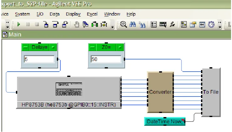
Some of the data flow programming languages are largely graphical. An ex-ample data flow programming language would be Agilent VEE [1]. In Agilent VEE, input (from both virtual and physical sensors as well as data generators) can be processed by graphically connecting sources to operation blocks and sending output to other operation blocks or actuators. See Figure 2.1 for an example.
The language used in the case study of this thesis is OIL. OIL provides a nested loop program description which is implemented as a mix of applicative and imperative elements. It was designed at NXP to be used in real-time systems and was implemented as one possible target for the NEST MPSoC hardware architecture which was developed at the University of Twente, see also the next chapter. The nature of NLP is a structure where a number of loops iterate over a stream of data. While the loops not necessarily process an unlimited amount of data, making the loop repeat endlessly will result in the processing of an infinite stream of data: stream processing. As such, this makes OIL especially suitable for streaming applications, where the streaming aspect is visible in an infinite loop in the algorithm.
2.3. APPLICATIVE LANGUAGES 13
Figure 2.1: Example of a Agilent VEE program
similar and even OpenMP uses something like this. In Figure 2.2 we see one control thread which branches into multiple tasks running in multiple threads. Eventually, the tasks end and the control flow returns to the control thread.
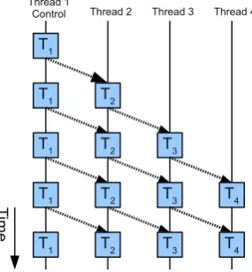
When we consider the model used with OIL, we have a control task to start the program which will then start tasks in parallel. These tasks do not end unless the program is terminated. See Figure 2.3 for an example. This form of ‘pipeline’ parallelism is clearly different from that of the other languages we just showed. As each task in the pipeline receives input, it becomes active until the entire pipeline is active.
OIL attempts to strike a balance between imperative and applicative or functional languages. The language semantics are similar to C but the ac-tual syntax has some fundamental deviations. The coordination language is used to describe nested loops: function calls (to functions written in another programming language) with explicit inputs and outputs within a (possibly infinite) loop.
The resulting dependencies between functions (based on the in- and out-put) and conditional program flow are then put in a model which looks mostly like a hybrid solution between one or more data flow models and a state ma-chine. Each function call is considered as an atomic task and as such is run as a task on a specific processor. When we assume a pool of infinite processors, each task will run on a processor and will be activated as soon as data is available.
14 CHAPTER 2. RELATED WORK
T
T T
T
T T T
T
T
im
e
Thread 1
[image:22.595.256.380.125.306.2]Control Thread 2 Thread 3
Figure 2.2: Example of the threading and communication model used in various parallel languages
T1
T1 T2
T
im
e
Thread 1
Control Thread 2 Thread 3 Thread 4
T1 T2 T3
T1 T2 T3 T4
T1 T2 T3 T4
Figure 2.3: Example of the threading and communication model used in OIL
which allows traditional imperative languages to be combined with applicative languages in a way that allows algorithms to be executed on parallel hardware. The internal data flow model is used to derive a task graph with an execution schedule which is guaranteed to be deadlock free.
The main strength of OIL is the prediction of real-time behaviour for the resulting program after compilation. Combined with the worst-case run times of each task, the compiler can devise a possible schedule for the available hardware which is guaranteed to satisfy throughput and latency constraints. Even combinations of OIL programs can be run on the same system with the guarantee that each algorithm will be executed within the boundaries as specified on compile time.
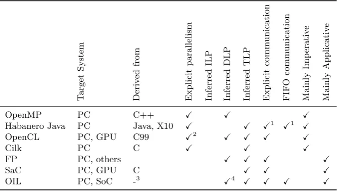
[image:22.595.248.391.356.510.2]2.3. APPLICATIVE LANGUAGES 15 T arget System Deriv ed from Explicit pa rallelism Inferred ILP Inferred DLP Inferred TLP Explicit comm unication FIF O comm unication Mainly Im p erativ e Mainly App licativ e
OpenMP PC C++ X X X
Habanero Java PC Java, X10 X X X1 X1 X
OpenCL PC, GPU C99 X2 X X X X
Cilk PC C X X X
FP PC, others X X X X
SaC PC, GPU C X X X
OIL PC, SoC -3
X4 X X X X
1Habanero consists of multiple projects, including the CnC library which handles
(amongst other things) communication.
2While OpenCL is a SIMD language, the kernels themselves have no parallel
structures.
3Based on NLP and applicative concepts.
4While OIL has no explicit DLP support, this can be inferred by creative usage
[image:23.595.92.426.126.315.2]of the syntax.
Table 2.1: Properties of various parallel languages compared
systems. Among the possible outputs (at the time of this writing) are:
• plain POSIX:suitable to be compiled and executed on ordinary Unix systems, normal POSIX threads are combined with a special wrapper for communication between tasks. Note that there is no explicit scheduling involved in this mode: tasks are executed as soon as their input buffers contain data and their output buffers are ready to accept new tokens.
• SystemC: The SystemC output allows the algorithm to be executed in a data flow simulator. The simulation provides deterministic temporal behaviour and should exhibit the parallel behaviour which was described in the coordination language.
• embedded system output: this output is used on a dedicated multi-core chip with a shared memory architecture. The tasks from the co-ordination language are mapped onto specific cores in such a way to guarantee their throughput and latency constraints. This target is us-ing a special real-time kernel [34] and uses software FIFO communication between tasks.
16 CHAPTER 2. RELATED WORK
functiong(y) will be executed when a value for y is available. Note that the execution of both functions can be in parallel.
def int x, y; x = 0;
while(1) {
f(x, out y); g(y); }
Code Listing 2.7: Example of OIL
2.4
Summary
In this chapter we discussed some parallel programming languages and intro-duced OIL. The different approach OIL takes has some advantages over other languages, most noticeably the ability to ‘embed’ blocks of another language while adding parallelism using an coordination language. This attribute will most likely prove valuable in the re-factoring of an existing algorithm if this algorithm was written in a imperative language like C. As the functionality of the original algorithm will still be compiled just like in the sequential version, the efficiency of the resulting OIL program is directly related to the efficiency of the implementation of the original algorithm.
As the applicative property is preferable to the imperative property when we want parallelism, as clear dependencies help in parallel execution, some of the languages we discussed attempt to bring the applicative aspect to an imperative language. While others like OIL or SaC might share semantics with an imperative language like C, they are actually mainly applicative.
CHAPTER
3
Platform
In the previous chapters, we looked at parallel programming languages and introduced the language called OIL, which will be used in the case study. As mentioned before, the OIL language has multiple target platforms. Besides the Unix targets, the OIL compiler, called Omphale, also supports the MPSoC architecture developed at the CAES group at the University of Twente.
The architecture was developed for the NEST project. Participants in the NEST project are Thales, Philips Medical Systems, Oc´e and Next eXPerience Semiconductors (NXP). The goal of the project is to research and exploit:
1. MPSoC architectures with means for low power, composability, and re-configurability.
2. A design flow for MPSoC based systems using high level synthesis.
3. An MPSoC run-time system management. By means of dynamic re-configuration, the run-time system is capable of dealing with adaptive service requirements and platform variability.
While the NEST architecture and Omphale tool kit are developed sepa-rately, the 2 systems have been connected to allow OIL based programs to run on the MPSoC.
In this chapter we will first introduce the architecture used for this case study. After explaining the general structure, we will explain which NoC designs are available for this architecture. Afterwards, we will look into 2 of the more complex tiles: the processing tiles and the ethernet tile. We will then explain why ethernet was chosen as a new tile for high speed I/O and present some results from testing the ethernet tile.
18 CHAPTER 3. PLATFORM
3.1
Overview
Within the NEST project a multi-processor architecture was designed for streaming applications. The architecture consists of processor tiles and periph-eral tiles which are all interconnected by means of a Network on Chip (NoC). This MPSoC architecture allows the system to scale to increase processing power and add new peripherals when needed.
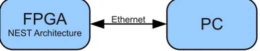
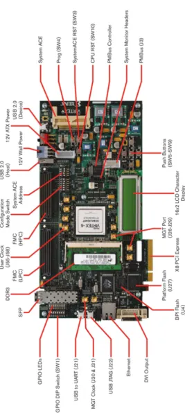
[image:26.595.192.450.346.397.2]One of the key aspects of the architecture is its scalability. The NoC is generated based on a simple specification and each processing tile is an instance of a template. The NEST architecture generator can generate a system description (in the VHSIC Hardware Description Language (VHDL) language) which can be simulated and synthesized for the target hardware platform. In this case study we use the architecture on a Field Programmable Gate Array (FPGA) in combination with a normal desktop computer, see Figure 3.1. Note that the processing tiles run at 100 MHz.
FPGA
NEST Architecture
PC
Ethernet
FPGA
NEST Architecture
Figure 3.1: Overview of the system set up
Inside the FPGA, we find the NoC which interconnects all tiles in the sys-tem. The network provides some guarantees about its behaviour, depending on the type. At least the lower bandwidth limit can be determined, as well as the upper limit on latency.
The processing tiles, labelled CPU Core # as shown in Figure 3.2, each contain a single CPU, and are almost identical1. Each processing tile has its own peripherals like timers and memory.
While processing tiles have their own private memory, these are very lim-ited in size (mere kilobytes) while most data intensive applications most likely need more storage. The memory tile connects a DDR memory bank to the architecture. Due to the fact that the design is using a distributed shared memory architecture in combination with Memory Mapped I/O (MMIO), the external memory can be easily accessed from each tile. The ML-605 evaluation board comes with a 512 MB memory bank.
To provide feedback and allow input from the outside world, the peripheral tile connects some LED lights and some push buttons to the system. Again, due to the sharing design of the system, these peripherals are available to all tiles.
1Each tile and CPU can be configured individually, for this case study all CPUs are all
3.2. NETWORK ON CHIP 19
Taking feedback another step further than a few blinking lights, is the DVI tile. This tile drives the display port on the testing board in order to send a video signal to an external monitor. While connected to the system, this tile uses the memory tile via the NoC to read its pixel data from the DDR memory. In order to produce visual output, other tiles need to write their image data in a reserved section of the DDR memory.
The last tile is an ethernet bridge. The ethernet tile gives an external device, like a computer, access to the entire system. This tile was created for this project and is used to stream radio data from and to the DDR memory.
Peripherals
PC
EthernetEthernet
BridgeNoC
NetworkingCPU
Core 0
CPU
Core 1CPU
Core 2...
CPU
Core NDVI
Monitor
DVI / VGA
Memory
Controller
[image:27.595.93.458.272.543.2]Buttons / LEDs
DDR3
Memory GPIO DDR3 N E S T A rc hi te ct ur e X ili nx V ir te x-6 F P G AFigure 3.2: Overview of the NEST MPSoC architecture
3.2
Network on Chip
20 CHAPTER 3. PLATFORM
3.2. NETWORK ON CHIP 21
3.2.1 Æthereal
Æthereal is a NoC which was developed at NXP as a scalable and highly reconfigurable network to replace traditional bus architectures for MPSoC systems [8]. It consists of routers which are connected to end points and to other routers to form a complete network.
The Æthereal tool kit can generate a network specification based on so called use cases. Depending on the application, more than one use case can be provided to the tool kit. Each use case describes which end point com-municates to which end point and specifies the type of service required: for example latency bounds can be set and guaranteed throughput (bandwidth) can be requested.
The resulting NoC is generated as VHDL and is composed by considering the specifications of all use cases and can be simulated as well as synthesized. A problem with Æthereal is the fact that it is using a connected network. This means that a dedicated point to point connection is provided. As each connection requires buffers and other logic, regardless of the actual implemen-tation of the link itself, each connection is expensive in terms of area. As the number of connections in a multi-core system increases exponentially with the number of cores, the use of a connected network becomes a major issue.
3.2.2 Warpfield
Since in some applications the features and guarantees of Æthereal are not required, a new type of NoC was developed at the University of Twente: Warpfield2. While Æthereal uses dedicated point to point connections with configurable bounds for latency and bandwidth, Warpfield uses a connection-less design where data packets are switched and routed as they travel through the network. Also, all peers can communicate with each other. The major advantage of this network is the reduction in area when compared to Æthe-real while still providing throughput and latency bounds. To illustrate this: the architecture has been generated for an FPGA for a 32 core system using a Warpfield network, at which point a lack of resources limited the number of CPUs. When using Æthereal, the network itself consumed a significant amount of resources, resulting in a 8 core system.
Warpfield uses fair scheduling and as such the network is starvation free. If a Warpfield NoC is used to connect N devices while the network has a total bandwidth of B, then every device on the network gets at least B/N
bandwidth, given equally sized transactions. When network peers do not use their bandwidth, unused bandwidth is available to the other peers. This is in contrast to Æthereal, which provides exactly the required amount of
2The work on Warpfield is unpublished and therefore only a global description is
22 CHAPTER 3. PLATFORM
bandwidth, but does not allow connections to use more than their requested bandwidth, even if the network is otherwise idle.
The latency bounds are a result from the fair packet scheduling as well. The worst case scenario would be a network under full load where a packet has to wait at each hop. Since the schedule is fair, and the number of hops in the network is limited, for each network configuration the upper latency bound can be determined.
As the entire design works at 100 MHz and the network uses communica-tion channels which are 32-bit wide, the throughput between peers is in the ideal case equal to 400 MB/s but because of protocol overhead throughput ranges from 133 MB/s up to 320 MB/s for bursts.
3.3
Processor Tile
The used processor architecture is the MicroBlaze soft processor core designed for Xilinx FPGAs. As a soft-core processor, the MicroBlaze is implemented entirely in the general-purpose memory and logic fabric of Xilinx FPGAs. The instruction-set architecture is based on RISC (Reduced Instruction Set Computing), a CPU design strategy used in many well known CPUs: ARM, SPARC, PowerPC and MIPS. The MicroBlaze has many aspects which can be user configured at design time, for example floating point support.
The processor is supported by a special GCC compiler. In the design used for this case study, each CPU is provided with a Floating Point Unit (FPU) and options like a barrel shifter and a hardware divider. Both the instruction cache as well as the data cache have 4 KB or more memory.
Each CPU has a small dual-port local memory which is used for some of the kernel administration. In general, all data and instructions are stored in the on-board DDR memory (which is accessed through the NoC).
The CPU is connected to its peripherals using a local bus, the Processor Local Bus (PLB). Both caches are connected to the PLB and so is the network bridge which connects the processor tile to the network. Note that a specific memory range is considered ‘local’ and all other addresses are assigned to the network interface to allow every device which is connected to the PLB access to the other tiles in the network.
A timer is used to fire interrupts to perform multi-threading by means of time slices and to keep track of time.
Finally, each tile has a dual-port scratch memory attached to the PLB which is also connected to the NoC. This memory has an address range on the NoC assigned to it and allows direct data passing between tiles (without using the DDR memory).
3.4. ETHERNET TILE 23
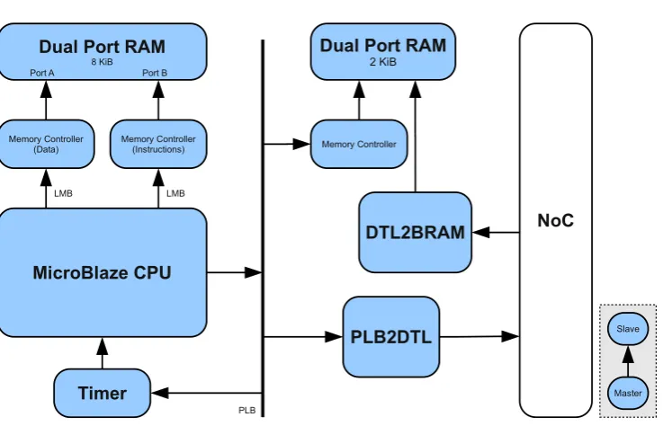
Dual Port RAM 8 KiB
Memory Controller
(Data) Memory Controller(Instructions)
MicroBlaze CPU
LMB LMB
Port A Port B
PLB
NoC
PLB2DTL Dual Port RAM
2 KiB
Memory Controller
DTL2BRAM
Slave
[image:31.595.93.462.114.351.2]Master Timer
Figure 3.4: Internals of the processing tile
3.4
Ethernet Tile
The case study, which is explained in chapter 4, will process large amounts of data. Even though the platform has DDR memory available, there was no reliable and fast way to perform I/O with the system. In this section we will explain why we chose ethernet to expand the I/O capabilities of the platform and how it was implemented.
Previously, only 2 methods of I/O for the platform were available. Either by means of the debugging interface of one of the MicroBlaze CPUs (optional, the debugging interface can be omitted) and the serial UART port. The latter requires a special initialisation of one of the CPUs in the system with an interpreter program in order to listen and process bytes from the serial port.
While the debugging port is marginally faster, the serial I/O is performed at a 115 kbps. Not only is this transfer speed insufficient when megabytes of data have to be transferred every second, but there is no support for flow control nor extensive error correction either. This makes up- and downloading data using the serial port on the NEST platform an unreliable operation.
The USB debugging interface for the MicroBlaze CPU provides access to a CPU with debugging support enabled but requires to suspend the processor in order to read or write data from the system. In other words: to use a MicroBlaze core for I/O on a streaming platform, the core would essentially be sacrificed to become a dedicated I/O component.
24 CHAPTER 3. PLATFORM
which could also be used for system I/O. The downside to using USB is the fact that special drivers need to be written which makes it an OS specific implementation.
The last problem we encountered was the fact that similar efforts were made to use the USB interface directly with the Æthereal network and only USB Full Speed was supported, meaning the I/O ran at 12 Mb/s.
The ML-605 evaluation board also has support for tri-speed ethernet. The full ethernet driver supports all ethernet modes up to full duplex 1 GBit/s LAN, but also consumes a lot of resources. Xilinx also provided a ‘light’ driver for the ethernet interface which requires almost no resources on the FPGA but is locked on a fixed network configuration and limited to 100 Mb/s.
3.4.1 Interface Requirements
The new interface tile will be called HSI which stands for High Speed Interface, a relative term based on the bandwidth of serial port it is meant to be replacing (a speed-up or bandwidth increase of roughly a factor 800).
The bridge IP will be designed as a peripheral tile on the NoC with the following requirements:
• The IP is to be designed with speed (throughput) in mind, at least 80 Mb/s is required.
• The IP will use an external interface type available on common comput-ers.
• The IP is stand-alone: it does not rely on other parts of the system (except the NoC).
• The IP is robust: external influences (commands, data) should not in-terfere with its functioning.
• The IP will be able to access most parts of the MPSoC system, for example by supporting MMIO.
Speed and type
The Xilinx board used for this project is the ML-605 which has numerous I/O connections. Most of these connections are not common on normal computers or would require a lot of effort to connect to a simple computer.
We selected the standard ethernet interface using the ‘light’ ethernet con-troller implementation on the ML-605. The concon-troller was set up to use the maximum speed of 100 Mb/s in full duplex mode.
Stand-alone and robustness
3.4. ETHERNET TILE 25
The most logical solution is to add a dedicated processor to the IP3. This allows data handling and parsing and because the behaviour is defined in software, it should be relatively simple to extend or improve the functionality of the IP.
Robustness can be achieved by keeping the software on the IP minimal-istic: no operating system, no multi-tasking. Even stripped down to simple firmware, a network stack should be provided in order to be able to commu-nicate with standard ethernet devices. In order to facilitate this, we created a minimal network stack which provides a partial implementation of a number of protocols, see section 3.5.
System Access
Since most parts of the MPSoC are addressable via the NoC, it stands to reason that the IP should use the NoC as well. This way, most peripherals of the MPSoC are memory mapped for the IP and access to other parts becomes trivial.
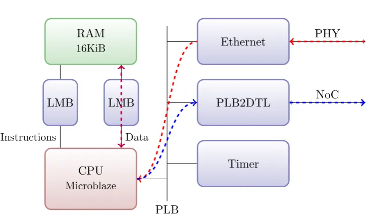
PLB CPU
Microblaze
LMB LMB
RAM
16KiB Ethernet
PLB2DTL
Timer
Instructions Data
PHY
NoC
Figure 3.5: Design of HSI bridge
3.4.2 Tile Overview
The original design is created using the Xilinx XPS software. This allowed for rapid prototyping to build the core for the peripheral tile which could be converted to an IP during integration. The result which was integrated with the NEST MPSoC system is shown in Figure 3.5.
3Note that unlike with the USB debugging interface, the CPU can be programmed to
26 CHAPTER 3. PLATFORM
3.4.3 Throughput
The ethernet network transmits and receives data at 100 Mb/s. This means each bit takes 1
100∗106 = 1∗10−8s= 10nsand each byte takes 80nsto transmit
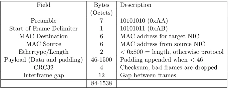
or receive. Since each packet which is exchanged over an IEEE 802.3 ethernet network contains at most 1538 bytes (see table 3.1), a complete packet is transferred in 1542∗80 ns ≈ 123 µs = 123∗10−6s. Since the MicroBlaze CPU in our system runs at 100 MHz, one ethernet packet is transferred in
123µs⇒ 1001∗106 = 10ns/cycle⇒ 12300010 = 12300 CPU cycles.
In other words: the HSI bridge needs to copy data words (4 bytes) in 32 CPU cycles or less to be able to reach maximum throughput (this includes overhead from loops and protocol handling before the data can be copied).
Field Bytes Description (Octets)
Preamble 7 10101010 (0xAA) Start-of-Frame Delimiter 1 10101011 (0xAB)
MAC Destination 6 MAC address for target NIC MAC Source 6 MAC address from source NIC Ethertype/Length 2 < 0x800 = length, otherwise protocol Payload (Data and padding) 46-1500 Padding appended when <46
CRC32 4 Checksum, bad frames are dropped Interframe gap 12 Gap between frames
[image:34.595.135.537.299.452.2]84-1538
Table 3.1: Overview of fields in a ethernet 802.3 frame
3.4.4 Measurements
One of the problems of the bridge design became visible during testing: the maximum speed of ethernet is not reached. To determine more accurately how long data transfers take, multiple performance tests were run to measure the actual times and speeds. To get accurate results, the speed of all data transfers between components is measured individually. The normal data flow is marked in Figure 3.6.
The total throughput is roughly the serial throughput of all components as measured before. Since early tests showed that protocol parsing takes less than 200 cycles and data transfers take thousands of cycles, the overhead of the protocol stack is neglected in the following sections.
3.4. ETHERNET TILE 27
PLB CPU
Microblaze
LMB LMB
RAM
16KiB Ethernet
PLB2DTL
Timer
Instructions Data
PHY
[image:35.595.95.459.109.323.2]NoC
Figure 3.6: HSI bridge with timer and data flow for storing data
3.4.5 CPU to DDR throughput
This test is meant to determine the maximum throughput from the HSI pro-cessor to the DDR memory.
A test program is used to generate data (for example, incrementing 32-bit integer values, e.g. the memory address itself) which is stored in DDR memory. This means no data is loaded from the local on-tile BRAM memory since all data is generated internally on the processor. The only overhead for each write is an increment for the memory pointer and the branch for the loop.
The design was altered to include a timer to track CPU cycles, see Fig-ure 3.6 for the system model and the data flow.
Measurements showed roughly 268.4∗106 cycles for 64 MB of data. Since transfers are done per word (= 4 bytes), exactly 16 cycles per word are required to store data from the CPU into DDR. Since the loop uses a counter which has to be incremented and a branch instruction for the loop itself which takes 3 cycles, actually storing a single word takes ∼12 cycles.
With a system clock of 100 MHz and 16 cycles per word, this means the maximum throughput or bandwidth is 200 Mb/s from CPU to DDR.
3.4.6 Local RAM to DDR throughput
28 CHAPTER 3. PLATFORM
and an ‘AND’ operation on the local memory pointer to loop (the ‘AND’ operation provides a mask on the read address since 64 MB is copied and the local memory is only 16 KB in size).
The measurement results confirm this: 318.8∗106 cycles for 64 MB of data means 19 cycles per word are needed to copy data from local memory to DDR.
With a system clock of 100 MHz and 19 cycles per word, this means the maximum throughput is∼168 Mb/s from local RAM to DDR.
3.4.7 Ethernet controller to local RAM
One of the final data flow paths is the transfer of data from the ethernet device buffers to the local memory. After data has been moved to local memory, the ethernet device can resume receiving data (note that there are parallel buffers: while at least one buffer is free, data is received from the physical network).
The first measurement was performed while ignoring the actual buffer status and while the network was idle to prevent external influences. The test copied 1500 bytes in 375 word transfers from the first receive buffer to the local memory.
Surprisingly enough, the read of the entire buffer was done in roughly 7,500 cycles. This means a single word is copied in∼20 cycles, even slower than the storing of words to the external DDR memory!
It seems that the Xilinx implementation of the ethernet device driver did not use ‘memcpy’ or a similar optimized function but rather implemented a similar algorithm. A few tests showed that memcpy was significantly faster so the driver was modified to perform the data copy using the ‘memcpy’ function. The results speak for themselves: the whole buffer of 1,500 bytes was copied in roughly 5,800 cycles. This means a single word is copied in 15 cycles, a speed-up of 25%!
Given the system clock of 100 MHz and 15 cycles per word, this means ∼213 Mb/s can be copied between the local ethernet controller and local memory.
3.4.8 Measurement Summary
3.5. NETWORK STACK 29
0 5 10 15 20 25
(128 Mb/s) 30 35 (80 Mb/s)40
CPU to DDR BRAM to DDR ETH to BRAM Combined
CPU cycles per word copy
Figure 3.7: Measured cycles required for word transfers (smaller is faster)
Initial testing (without using ‘memcpy’ to copy data buffers from the eth-ernet device) showed a throughput of ∼70 Mb/s. If the remote host would attempt to increase throughput beyond that point it would result in packet loss (increasing total used bandwidth but reducing actual throughput as pack-ets would be discarded, resulting in zero gain). After tweaking the software (using ‘memcpy’ on the initial data transfer for example), throughput was increased to∼91 Mb/s, without any packet loss.
Since the required bandwidth for our case study is 80 Mb/s in order to be real-time, this performance is acceptable (see also chapter 4).
3.5
Network Stack
One of the problems when building a bridge between a NoC in an architecture and a physical ethernet network is the question which protocol stack should be used. The most simple solution is to implement no protocol stack at all.
The first problem with this approach is the fact that all routing and use of standard IEEE 802 compatible equipment becomes impossible. This means that the most minimalistic viable approach should at least implement the Media Access Control (MAC) layer (IEEE 802.3).
The easiest solution would be to implement a basic protocol stack to be able to use standard network access to communicate with other devices on the network. Since the goal is to use the solution for an embedded and real-time environment, a minimalistic implementation will suffice.
30 CHAPTER 3. PLATFORM
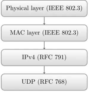
Resolution Protocol (ARP). In case of IPv4 as in Figure 3.8, another protocol is wrapped inside the IPv4 [21] structure. This could be Internet Control Message Protocol (ICMP) [23], Transmission Control Protocol (TCP) [22] or in this case User Datagram Protocol (UDP) [29].
Physical layer (IEEE 802.3)
MAC layer (IEEE 802.3)
IPv4 (RFC 791)
[image:38.595.245.395.196.351.2]UDP (RFC 768)
Figure 3.8: Typical network stack for UDP
The protocol stack in the bridge supports a subset of ARP (to communi-cate its IPv4 address to other devices on the network), a subset of ICMP (to be able to ‘ping’ the bridge to test connectivity, none of the error handling is implemented or needed) and a subset of IPv4 with basic UDP support. The IPv4 implementation supports non-fragmented frames up to the normal size (1,538 bytes) and the UDP implementation is complete except for checksum checking and generation for payloads (to save CPU cycles).
This minimalistic network stack has a binary footprint of ∼19 KB. As a reference, the complete IPv4 implementation (without ‘netfilter’) as used in the 2.6.34 kernel of the Linux operating system is ∼1.6 MB as binary. That means the full implementation is over 86 times the size of the embedded stack while the latter is still able to interact with most devices on a network. The hierarchy of the resulting stack can be found in figure 3.9.
3.6
Future Work
In this section we will propose 2 future optimisations which can improve the performance of the HSI tile.
3.7. CONCLUSION 31
MAC
ARP IPv4
ICMP UDP
[image:39.595.182.365.123.334.2]Application
Figure 3.9: Components from the implemented (minimal) network stack
the architecture, the required 16 MB/s for ‘uncompressed’ DAB signal can be achieved4.
A second performance boost can come from the use of a DMA controller. Testing showed that a DMA controller only needs 8 cycles per word copy from and to shared memory. This is considerably faster than the 20 cycles it takes the MicroBlaze CPU to write a word to shared memory. Using the DMA controller on local memory as source will mean even lower copy times. This will boost throughput in the HSI tile but will also lower the load on shared memory as the DMA controller will use bursts to write its data, which is faster than separate word writes.
The DMA controller was tested on a (manually) modified architecture. As the DMA controller is not well supported at this time, the actual mapping is performed without it.
3.7
Conclusion
In this chapter, we described the used platform and its components and the extension that was added to the NEST system in order to be able to use the platform for the case study. We explained the choice for implementing a peripheral tile with ethernet support to improve the I/O capabilities of the NEST platform. After evaluating the performance of the new ethernet tile a pair of possible performance improvements are suggested.
4The radio signal actually uses 10-bits, packing these bits together results in a signal at
32 CHAPTER 3. PLATFORM
A detailed overview of the HSI network protocol and its features can be found in Appendix A.
CHAPTER
4
Digital Audio Broadcasting
In this thesis we will study the mapping of a DAB decoder algorithm onto a multi-core system. In this chapter we will introduce and explain how DAB works.
Digital Audio Broadcasting is a digital radio technology for broadcasting radio stations. Mostly used in various countries in Europe, it was developed in the late eighties in a European project as a replacement for analogue ra-dio broadcasting technologies. One of the key aspects of the standard was to bundle multiple radio streams in one DAB signal and to improve radio broad-casting in terms of spectral efficiency, quality of reception, and in quality of sound.
Both spectral efficiency and sound quality are directly related to the fact that a digital radio technology as DAB uses a digital encoding to transport the sound. The used audio encoding technology is MPEG Audio Layer II, which was a state of the art encoding during the development of DAB and is still widely used in for example DVDs. A problem with using such a digital audio encoding is a result from the fact that the digital DAB carrier has a fixed bandwidth. As such, the number of radio channels available in a single DAB stream is inversely proportional to the bit-rate of the encoded audio, and as such, the audio quality. This resulted in a negative image for DAB broadcasts starting in the 90’s in the United Kingdom where the BBC started to reduce audio bit-rates to broadcast more radio channels. This resulted in a reduction in perceived audio quality of DAB which was lower than analogue FM transmissions1 [4, 11].
Some of the digital technology used in the DAB standard is meant to improve reception. While analogue radio reception quality gradually degrades
1DAB supports bit-rates from 64 kb/s for speech, up to 256 kb/s for high fidelity music.
Common bit-rates in the UK are 128 kb/s for music stations while at least 192 kb/s is required to improve FM radio audio quality [11].
34 CHAPTER 4. DIGITAL AUDIO BROADCASTING
with decreasing signal, DAB reception remains excellent until the signal falls below a critical threshold. The used transmission technology, called OFDM, is still used today in technologies like WiFi. The use of OFDM results in more robust broadcasts, even in mobile settings, where noise and multi-path distortions are no longer affecting reception. Another benefit is that OFDM transmissions of the same broadcast can be transmitted on the air at the same frequency at multiple, geographically spaced, antennas. In contrast, analogue FM transmissions require that each antenna with an overlap in coverage uses a (slightly) different frequency, forcing mobile listeners to re-tune their receivers as they move from the coverage of one antenna to the next.
The technical base, the physical layer, of DAB is used in newer standards like DMB and DAB+ [36]. DMB adds support for video and multimedia broadcasting, resulting in a digital mobile television platform. DAB+ ad-dresses some of the problems of the old DAB standard: better error correction (Reed-Solomon) to improve reception and a better audio encoding technology, called MPEG-4 audio or AAC+, make DAB+ the successor of DAB.
At the time of writing, the Netherlands are aiming to reach an 80% national DAB+ coverage by the year 2015 using channel 11C. This excludes regional radio broadcasts which will be transmitted using a different channel. See Figure 4.2 for a map of the expected coverage of the Netherlands by 2015, see Figure 4.1 for the current situation. Clearly, after 25 years, DAB radio is still not widely accepted despite the advantages over FM radio.
In the next section, we will explain the transmission technique used by DAB. In the following section, the internal structure of a DAB transmission is explained. Afterwards, we will relate the presented transmission structure to the decoding of it in a schematic overview of a DAB decoder.
4.1
OFDM
Coded Orthogonal Frequency-Division Multiplexing (COFDM), also known simply as OFDM, is a transmission method where instead of one carrier fre-quency, data is transmitted in several smaller carrier frequencies. The deci-mation of data in frequency means the data rate in all these sub-carriers can be much lower compared to when one carrier would need to carry all data. DAB Transmission Mode 1 uses 1536 carriers, spaced 1 kHz apart from each other. See Figure 4.3 for a visualisation of OFDM.
4.2. STRUCTURE 35
Figure 4.1: DAB coverage area in the Netherlands in 2009 [24]
constellation diagram is shown which can be used to decode the sub-carrier payload based on the complex signal phase2. Combining the D-QPSK encoded bits for all sub-carriers yields the data for the entire symbol. When regarding Transmission Mode 1, 1536 carriers with each 2 bits yields a symbol size of 3072 bits, see also Table 4.2.
The advantage of using OFDM for radio transmission is that the length of a single symbol in the DAB stream takes over a millisecond of time. At such speeds, accurately detecting the symbol value is possible. Also, multi-path reception from reflections of buildings and other environmental influences can be easily countered.
Besides data frequency interleaving due to the use of OFDM, time inter-leaving is also used: this means the data bits are spread over different carriers at different times. The result is that signal loss can be countered for impulse interference or short drop-outs.
4.2
Structure
A DAB radio stream consists of an endless stream of so called frames. Frames are separated by null symbols, where a null symbol is defined as a gap between
2The shown constellation diagram is for illustration purposes and might not be the same
36 CHAPTER 4. DIGITAL AUDIO BROADCASTING
Figure 4.2: DAB+ coverage area in the Netherlands in 2015 [24]
Figure 4.3: Visualisation of OFDM in both time and frequency
frames, in time, with zero energy. A single DAB frame consists of multiple symbols. A null symbol has a different length (in time) compared to a symbol from a frame. The number of symbols per frame is determined by the used Transmission Mode where DAB has 4 different modes. See Table 4.2 for details [35].
[image:44.595.177.466.368.509.2]4.3. DAB DECODER 37
11
10 00
01
Q
[image:45.595.195.356.124.297.2]I
Figure 4.4: Quadrature Phase Shift Keying constellation diagram
channel is requested.
To further protect the data integrity, all the data in the DAB frames are encoded using Viterbi, an encoding scheme to detect and correct transmission errors to reconstruct the original data. Because the FIC is more important than the Main Service Channel (MSC) (a corrupt FIC makes an entire frame useless, a corrupt MSC makes for a small glitch or gap in the audio stream, most likely unnoticeable to human ears), the Viterbi encoding scheme is dif-ferent for difdif-ferent parts of the frame. As such, de-puncturing is used with the Viterbi encoding to alter the number of encoding bits to encode data bits.
Null TFPR FIC
0
FIC
1
FIC
2
MSC
0
MSC
1
..
.
..
.
..
.
MSC
70
MSC
71
Table 4.1: Symbol overview of the structure of a DAB frame
4.3
DAB Decoder
In this section, the structure of the decoder is described at a high level. The decoder actually has 2 states toward producing radio output: tuning and decoding, as shown in Figure 4.5.
[image:45.595.159.388.486.534.2]38 CHAPTER 4. DIGITAL AUDIO BROADCASTING
Parameter Mode I Mode IV Mode II Mode III
Sub-carriers
Number of sub-carriers: K 1536 768 384 192 Sub-carrier spacing: ∆f 1 kHz 2 kHz 4 kHz 8 kHz
Time relations
Transmission frame duration: TF rame 96 ms 48 ms 24 ms 24 ms Symbol duration: TsymOF DM=Tguard+Tu 1246µs 623µs 312µs 156µs
Guard interval duration: Tguard 246µs 123µs 62µs 31µs
Symbol