Partitioning Technique for 3D ICs based on Power
Density
R. Jayagowri1, Kavya Bhat2
1, 2
Department of Electronics and Communication, BMSCE, Bangalore
Abstract: IC technology has witnessed miniaturization consistently over a period of time. Enormous number of devices are placed densely compared to their older counterparts. 3D IC packaging is one of the famous packaging technologies where in IC contains multiple dies having various modules or sub-systems interconnected through TSVs (Through Silicon Via). One of major challenges in 3D IC packaging is thermal management. This paper proposes a partitioning technique that helps to improve heat sinking in especially Flip-chip packaged 3D ICs. The main motive of the proposed partitioning technique is to place more heat producing modules in the netlist closer to heat sink, so that it helps for maximum heat removal during IC operation.
Keywords: Partitioning, 3D ICs, Flip-chip packaging, Heat sinking, power density
I. INTRODUCTION
Human life has changed and made easy greatly after the invention of IC technology. This has become the base of modern communication technology, computer technology, information technology and many more. Semiconductor industry has witnessed huge miniaturization of device in order to improvise the device characteristics, reduce power consumption and to make it faster and faster. Today we are in VLSI (Very Large-Scale Integration) era and we are leading to ULSI (Ultra Large-Scale Integration). One of the very important steps of VLSI technology is physical design of ICs. An IC with excellent logic design but poor physical design will certainly fail. Physical design deals with actual fabrication of the design on silicon wafer along with meeting all chip logic implementation and meeting all chip constraints. Parameters that are verified in every stage of physical design are timing, power density and connectivity etc.
Partitioning of modules is the very first step in physical design of any ICs. This step is the base for efficient physical design. Input for partitioning is the netlist of IC, technology libraries and constraint files. Partitioning step divides the overall logic devices into different groups such that the overall wire length is optimal while meeting all circuit constraints. Based on the constraints, the partitioning output varies for same input netlist. In earlier ICs bigger than sub-micron technologies, wire length reduction was the main constraint in physical design. But as the technology entered sub-micron dimensions, different parameters also started playing key role in proper and sustainable performance of ICs. One of such vital parameters is Temperature. More and more device scaling and packaging techniques such as 3D IC stacking led to increase in Power densities of ICs leading to creation of Thermal hotspots in ICs during their operation. This will eventually lead to IC damage and will reduce the mean time-to failure (MTTF) of the chips. Few relevant research papers have been studied related to existing partition techniques of 3D ICs. In [1], authors have proposed a partitioning technique for 3D ICs that is based on process called layer assignment. The technique proposed uses adjacency matrix of a graph for layer assignment problem. [2] proposes a netlist partitioning technique that aims to minimize the inter-layer interconnections while maintaining area constraints. In [3], authors have proposed a novel procedure to reduce TSV count as well as total wire length of circuit simultaneously. A partitioning technique that helps to reduce rise in temperature is proposed in [4]. This algorithm is based on Compact resistive Network Thermal Model and Integer Linear Programming (ILP) approach. In [5], authors propose a successive two-way partitioning method for 3D ICs that divide the circuit in to k-layers, under power density constraints. This algorithm also tries to minimize signal TSV and area overhead while maintaining power considerations. Electro-migration aware partitioning technique for 3D ICs is proposed in [6]. In [7], authors propose Thermal aware 3D partitioning technique in which modules with high power densities are placed at the bottom in the 3D stack structure and modules with relatively low power densities are placed at the top.
II. PROPOSEDPARTITIONINGTECHNIQUEFOR3DICS
The proposed Partitioning technique for 3D ICs focuses on arranging the modules in such a way that maximum heat sinking is facilitated from IC. This algorithm is not based on complex mathematical functions, rather it is based on a specific logic of module movement among different layers in 3D IC. This algorithm would estimate the heat produced by each module in the netlist based on its power density. The basic understanding is that the module that has maximum power density will lead to higher power dissipation. Thus, this partitioning technique doesn’t employ complex thermal modelling and hence this easy to understand and implement. Below sub-sections explain the proposed partitioning technique in detail.
A. Inputs to the Partitioning Technique
Following are the inputs to the proposed Partitioning technique for 3D ICs:
i) Unpartitioned netlist of the design with module list
ii) Number of layers in which the given netlist needs to be partitioned
iii)Area info of each module in the netlist
iv)Power density values for each module in the netlist
B. Steps Involved in Proposed Partitioning Technique
The steps involved in proposed Partitioning technique are explained below in sequential steps: 1) Read all inputs of the algorithm as shown below:
a) Let set ‘V’ represent the input netlist with list of modules in it
b) Let set ‘V_area’ contain area of each module in netlist ‘V’ in the same order
c) Let set ‘V_power’ contain power density values of each module in netlist ‘V’ in the same order d) Let ‘K’ represent the number of layers in which given netlist needs to be partitioned
2) Sort the modules of input netlist ‘V’ in descending order of their power density values. Let the new set be ‘V_sorted’. Thus after sorting, the first module in set ‘V_sorted’ will contain module with highest power density and the last module will be the module with least power density. Update sets ‘V_power’ and ‘V_area’ in such a way that the power density and area values in these sets correspond to modules in ‘V_sorted’ in the same order.
3) Read the number of modules present in input netlist ‘V’. Call it as ‘module_count’.
4) Calculate average layer area considering all the modules present in the netlist as shown below:
=
_ where represents the average layer area.
5) Consider an array (say) ‘A_layer’ of K number of elements for calculation. Let all the array elements hold the value ‘0’ initially. This array will hold the final partitioned netlist after the following step. Also consider following variables with initial values as mentioned below, which are needed for further calculation:
_ = 0 _ = 0
_ [] =
Here, demark_ref[] array is considered to keep a record of from which module in ‘V_sorted’ each layer has been assigned with. 6) The logic of partitioning the modules among different layers is given in pseudocode below:
ℎ (( _ ! = ) ( _ ! = _ )):
(( _ [ _ ] + _ [ _ ] ) ≤ ):
_ [ _ ] = _ [ _ ] + _ [ _ ]
( _ < _ ):
_ = _ + 1
( _ < ):
_ = _ + 1
_ [ _ + 1] = [ _ ]
ℎ
7) If there are modules left out after step (VI) in set ‘V_sorted’, then assign those modules to top layer.
Above mentioned partitioning technique tries to assign modules in ‘V_sorted’ set from bottom to top layer satisfying following two criteria:
a) If sum of area of the modules present in a layer in 3D IC doesn’t exceed after appending a module from ‘V_sorted’ set then, that module can be moved to the layer. If this condition is not satisfied, then assign this module from ‘V_sorted’ set to the next layer. Note that module assignment from ‘V_sorted’ set is carried out from its first module with highest power density in sequential order.
b) If there are modules left in ‘V_sorted’ set which don not satisfy criterion explained above in (i) for any layer, then those modules will be assigned to top layer of 3D IC. These would be the modules with lower power density values.
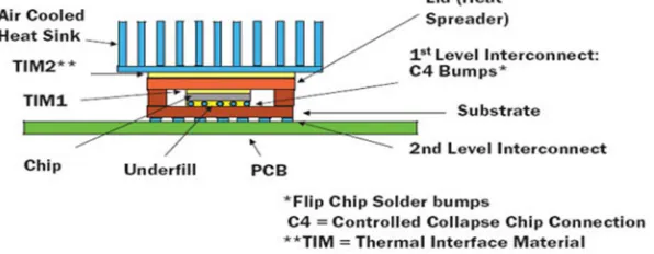
[image:3.612.164.462.296.412.2]By this approach, highest power density modules are assigned to bottom layer of 3D IC and lower power density modules will be assigned to top layers. In Flip-chip packaging technology, the IC is flipped to make electrical contacts with the base PCB. Thus, bottom layer comes closer to the heat sink after IC is flipped. Modules which produce highest amount of heat are assigned to bottom layer in this partitioning technique, which is placed closer to the heat sink after packaging. This facilitates removal of maximum amount of heat from the chip, avoiding the rise in chip temperature and creation of thermal hotspots. Thus, the proposed partitioning technique helps for better thermal management and hence it helps to improve the life time of the chips. A pictorial representation of Flip-chip 3D IC is shown in Figure 1.
Figure 1. Pictorial representation of Flip-chip packaging of 3D IC [8]
III.EXPERIMENTALRESULTSANDANALYSIS
The proposed partitioning technique is implemented using C language on a PC with 16GB RAM and with Linux OS. A set of example netlist was considered for validating the proposed partitioning technique. Table I shows a simple netlist considered for experiment with 10 modules in with their area and power density values. This technique can be applied on any netlist given that area and power density values of each module in netlist are available. As mentioned in the below table, there are 10 modules (m1 to m10) in the netlist which need to be partitioned in 3 layers. 3 number of layers are considered for testing the proposed technique. However, implemented algorithm is flexible enough to take different number of layers as input given the condition that the number doesn’t exceed the number of modules present in the input netlist. Here no specific unit of dimension is considered as the proposed technique doesn’t depend on unit of dimensions
TABLEI
Input Netlist Considered For Testing
Module list Area of each module Power density of each module
m1 3.1 units 2.2 units
m2 4.2 units 5.9 units
m3 3.8 units 3.1 units
m4 2.15 units 1.0 units
m5 5.8 units 7.8 units
m6 4.9 units 6.2 units
m7 0.8 units 2.0 units
m8 3.9 units 5.4 units
m9 1.2 units 1.8 units
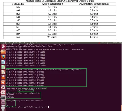
[image:3.612.69.538.577.731.2]Here, No. of input modules in the list = 10. Thus, module_count = 10. No. of 3D layers in which partition should take place = 3. Thus, K = 3. Total area of all input modules = 32.65 units
Average area of each layer, = Total Area / No. of layers = 32.65 / 3 = 10.883 units
First, the modules are sorted in descending order of their power density values. Table II shows modules after sorting in descending order of their power densities. According to the algorithm, the modules with highest power density will be assigned to bottom most layer and the modules with lower power densities will be assigned to upper layers with constraint: area of each layer should not exceed . Top layer is an exception for this constraint which may have area more than in some cases. Top layer with larger area will not affect the balance of the structure as top layer will come at the bottom after flipping the IC during packaging. Advantage of having area constraint is to distribute the modules among different layers in such a way that there will not be imbalanced area among different layers of the 3D IC. If few layers get considerably large area than other layers then, there is a chance of having dead spaces in 3D IC. Figure 1 shows the results obtained for input netlist mentioned in Table I.
TABLEII
Modules Sorted In Descending Order Of Their Power Density Values
Module list Area of each module Power density of each module
m5 5.8 units 7.8 units
m6 4.9 units 6.2 units
m2 4.2 units 5.9 units
m8 3.9 units 5.4 units
m10 2.8 units 3.5 units
m3 3.8 units 3.1 units
m1 3.1 units 2.2 units
m7 0.8 units 2.0 units
m9 1.2 units 1.8 units
m4 2.15 units 1.0 units
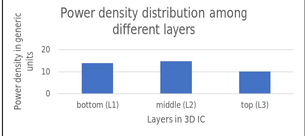
[image:4.612.61.562.266.724.2]Figure 3. Power density distribution among different layers of 3D IC after partitioning
Area of each layer after partitioning is given below (L1 represents the bottom layer): L1 area = 10.70 units
L2 area = 8.10 units L3 area = 13.85 units
Demarcation in sorted module list shown in Table II: L1 – from module 5
L2 – from module 2 L3 – from module 10
Figure 3 shows power density distribution among three layers of the 3D IC. As we can see, after the area constraint the bottom layer has 14 units, middle layer has 14.8 units and top layer has 10.1 units of power density.
IV.CONCLUSIONS
This paper proposes a simple yet effective partitioning technique for facilitating maximum heat removal from 3D IC during its operation. This helps in reducing the overall temperature of IC and creation of thermal hotspots and hence helps to avoid damage to the IC. The proposed partitioning technique is implemented using C language on a machine with Linux OS. A sample set of modules is considered for validating the proposed partitioning technique. Results are presented and analyzed. It can be seen that bottom layers are assigned higher power density modules which produce more heat compared to top layers in 3D IC. As heat sink will be closer to the bottom layer of the IC after Flip-chip packaging, it helps to improve heat sinking from IC during its operation.
V. ACKNOWLEDGMENT
We would like to thank Department of Electronics and Communication, BMS College of Engineering, Bangalore for the constant support throughout this work. We would also thank Mr. Sabyasachee Banarjee for his suggestions and help for this work.
REFERENCES
[1] Ajoy Kumar Khan, Sudipta Roy, Bhaskar Das, Rajat Kumar Pal, “A New Efficient Layer Assignment Algorithm for Partitioning in 3D VLSI Physical Design”, Conference proceedings of 2013 1st International Conference on Emerging Trends and Applications in Computer Science, Shillong India, Sept. 2013. [2] Sabyasachee Banerjee, Subhashis Majumder, Bhargab B. Bhattacharya, “A Graph Based 3D IC Partitioning Technique”, Conference Proceedings of 2014
IEEE Comp`uter Society Annual Symposium on VLSI, Tampa, USA, July 2014.
[3] Yung-Hao Lai, Yang Lang Chang, Jyh-Perng Fang, Jie Lee, “Simultaneous Layer-aware and Region-aware Partitioning for 3D IC”, Conference Proceedings of 2016 IEEE Asia Pacific Conference on Circuits and Systems, Jeju, South Korea, October 2016.
[4] Hua-Hsin Yeh, Shih-Hsu Huang, Kuan-Hui Li, “3D IC Design Partitioning for Temperature Rise Minimization”, Conference Proceedings of 2011 6th International Microsystems, Packaging, Assembly and Circuits Technology Conference, Taipei, Taiwan, October 2011.
[5] Ho-Lin Chang, Hsiang-Cheng Lai, Tsu-Yun Hsueh, Wei-Kai Cheng, Mely Chen Chi, “A 3D IC Design Partitioning Algorithm with Power Consideration”, Conference Proceedings on 13th Iternational Symposium on Quality Electronic Design, Santa Clara, CA, USA, March 2012.
[6] Tiantao Lu, Zhiyuan Yang and Ankur Srivastava, “Electromigration-Aware Placement for 3D-ICs”, Conference Proceeding of 17th Internal Symposium on Quality Electronic Design, Santa Clara, CA, USA, March 2016.
[7] Sabyasachee Banerjee, Subhashis Majumder, “A Thermal Aware 3D IC Partitioning Technique”, Conference Proceedings of 18th International Symposium on VLSI Design and Test, Coimbatore, India, July 2014.
[8] Bruce Guenin, ‘Packaging Challenges For High Heat Flux Devices’. [Online]. Available: https://www.electronics-cooling.com/2006/08/packaging-challenges-for-high-heat-flux-devices/ . [Accessed: 05-Mar-2019]
0 10 20
bottom (L1) middle (L2) top (L3)
P
o
we
r
d
en
si
ty
in
g
en
er
ic
u
n
it
s
Layers in 3D IC