Comparison Between Direct and Indirect Field
Oriented Control of Induction Motor
Venu Gopal B T
Research Scholar, Department of Electrical Engineering UVCE, Bangalore University, Bengaluru
ABSTRACT - Vector control, also called field-oriented control (FOC), is a Variable frequency Drive (VFD) control method in which the stator currents of a 3 phase induction motor are identified as two orthogonal components that can be visualized with a vector. The vector control of induction motors is one of the most suitable and popular speed control technique presently used. The vector control technique decouples the two components of stator current space vector: one providing the control of flux and the other providing the control of torque. The two components are defined in the synchronously rotating reference frame. With the help of this control technique the induction motor can replace a separately excited dc motor. The scalar control technique is simple to implement but have the coupling effect ultimately responsible for the sluggish response, which leads to instability due to higher order system effect. The DC motor needs time to time maintenance of commutator, brushes and brush holders. The main effort is to replace DC motor by an induction motor and merge the advantages of both the motors together into variable speed brushless motor drive and eliminate the associated problems. The squirrel cage induction motor being simple, rugged, and cheap and requiring less maintenance, has been widely used motor for fixed speed application. The induction motor is transformed from a non-linear to linear control plant. It is expected that with increasing computational power of the DSP controllers, it will eventually nearly universally displace scalar volts -per-Hertz (V/f) control. In this paper we will come to know the concept of vector control and different types of vector control techniques available. And finally we will be able to compare them.
Key words-Induction Motor, Vector Control, Scalar Control, Sluggish, Higher Order System Effect, DSP.
I. INTRODUCTION
ALMOST 45 years ago, in 1971 F. Blaschke presented the first paper on field-oriented control (FOC) for induction motors. Since that time, the technique was completely developed and today field oriented controlled drives are industrial reality and are available on the market by several producers and with different
solutions and performance. Thirteen years later, a new technique for the torque control of
induction motors was developed and presented by I.Takahashi
as direct torque control (DTC) and by M. Depenbrock as direct self control (DSC). Since the beginning, the new technique was characterized by simplicity, good performance and robustness . Using DTC or DSC it is possible to obtain a good dynamic control of the torque without any mechanical transducers on the machine shaft. Thus, DTC and DSC can be considered as “sensor less type” control techniques. The basic scheme of DSC is preferable in the high power range applications.
Now a days more than 60% of all the electrical energy generated in the world is used by cage induction machines Variable speed or adjustable torque control of electrical motor drives are crucial components in almost all-modern industrial manufacturing processes. Traditionally variable speed electric machines were based on dc motors, but for the last 45 years, Ac drives using induction machines are now finding increasing acceptance in various industrial applications because of the performance they can provide. The development of high performance control strategies for ac drives, driven by industry requirements has followed a rapid evolution during the last two decades. On the other hand, D.C machines have been used for variable speed applications. In DC machines mmf axis is established at 90˚ electrical to the main field axis. The electromagnetic torque is proportional to the product of field flux and armature current. Field flux is proportional to the field current and is unaffected by the armature current because of orthogonal orientation between armature mmf and field mmf .Therefore in a separately excited DC machine , with a constant value of field flux the torque s directly proportional to the armature current.
also become better with time. In 1980s, DC motor drives were generally used in variable speed drives because of the simplicity of control due to decoupling between armature current & the field current.
The control & estimation of ac drives in general is considered more complex than those of dc drives, & this complexity increase substantially if performance are demanded. To control the induction motor there are different types of control are there they are:
Variable supply voltage control Variable rotor resistance control
Constant Volts/Hz control (scalar control) Direct torque control
Vector Control
The name direct torque control is derived by the fact that, on
the basis of the errors between the reference and the estimated
values of torque and flux, it is possible to directly control the
inverter states in order to reduce the torque and flux errors within the prefixed band limits. Unlike FOC, DTC does not require any current regulator, coordinate transformation and PWM signals generator (as a consequence timers are not required). In spite of its simplicity, DTC allows a good torque control in steady-state and transient operating conditions to be obtained. The problem is to quantify how good the torque control is with respect to FOC. In addition, this controller is very little sensible to the parameters detuning in comparison with FOC. On the other hand, it is well known that DTC presents some disadvantages that can be summarized in the following points:
1) difficulty to control torque and flux at very low speed;
2) high current and torque ripple;
3) variable switching frequency behaviour; 4) high noise level at low speed;
5) lack of direct current control.
It is now recognized that the two high-performance control strategies for induction motor drives are Field Oriented Control (FOC) and Direct Torque Control(DTC) . Both FOC and DTC are strategies allow torque and flux to be decoupled and controlled independently. In the dc machine, this decoupling is obtained in an electromagnetic way by orienting the current with respect to the stator flux using a commutator.
In ac machines, this decoupling is obtained by implementing
mathematical transformations, thereby avoiding problems due to the commutator. The mentioned control techniques have undergone considerable research over the last 20 years, but several problems remain. The implementation of those concepts was possible due to technological developments such as the DSP controllers and the new power semiconductors. The electrical DC drive systems are still used in a wide range of industrial applications, although they are less reliable than the AC drives. Their advantage consists in simple and precise
command and control structures.
There are two fundamental directions for the induction motor control:
• Analogue: direct measurement of the machine parameters (mainly the rotor speed), which are compared to the reference signals through closed control loops;
• Digital: estimation of the machine parameters in the sensor less control schemes (without measuring the rotor speed), with the following implementation methodologies:
• Slip frequency calculation method; • Speed estimation using state equation;
• Estimation based on slot space harmonic voltages; • Flux estimation and flux vector control;
• Direct control of torque and flux;
• Observer-based speed sensor less control; • Model reference adaptive systems; • Kalman filtering techniques;
• Sensor less control with parameter adaptation; • Neural network based sensor less control; • Fuzzy-logic based sensor less control.
The interest in sensor less drives of induction motor has grown significantly over the past few years due to some of their advantages, such as mechanical robustness, simple construction and less maintenance. These applications include pumps and fans paper and textile mills, subway and locomotive propulsions, electric and hybrid vehicles, machine tools and robotics, home appliances, heat pumps and air conditioners, rolling mills, wind generation systems etc.
speed regulation, fast dynamic response, and operation above base speed. The choice of technique is vital in determining the overall characteristics and performance of the drive, during normal operation the control strategy must ensure that motor operation is restricted to the regions of high torque per ampere, there by matching the inverter ratings and minimizing the system losses. Overload or fault conditions must be handled by sophisticated control rather than over design.
2. FIELD ORIENTED CONTROL
Scalar control such as the “V/Hz” strategy has its limitations in terms of performance. The scalar control method for induction motors generates oscillations on the produced torque. Hence to achieve better dynamic performance, a more superior control scheme is needed for Induction Motor. With the mathematical processing capabilities offered by the micro-controllers, digital signal processors and FGPA, advanced control strategies can be implemented to decouple the torque generation and the magnetization functions in an AC induction motor. This decoupled torque and magnetization flux is commonly called rotor Flux Oriented Control (FOC).
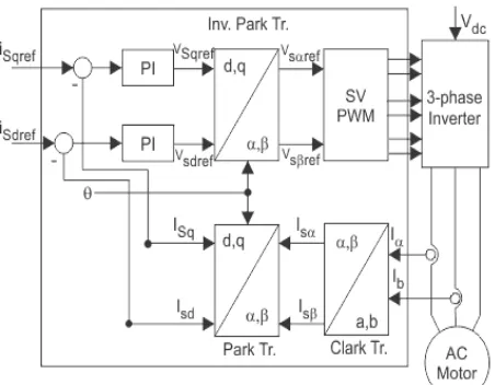
Figure 1: Simplified Indirect FOC
Field Oriented Control describes the way in which the control of torque and speed are directly based on the electromagnetic state of the motor, similar to a DC motor. FOC is the first technology to control the “real” motor control variables of torque and flux. With decoupling between the stator current components (magnetizing flux and torque), the torque producing component of the stator flux can be controlled independently. Decoupled control, at low speeds, the magnetization state of motor can be maintained at the appropriate level, and the torque can be controlled to
regulate the speed. “FOC has been solely developed for high-performance motor applications which can operate smoothly over the wide speed range, can produce full torque at zero speed, and is capable of quick acceleration and deceleration”.
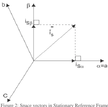
The field oriented control consists of controlling the stator currents represented by a vector. This control is based on projections that transform a three phase time and speed dependent system into a two coordinate (d and q frame) time invariant system. These transformations and projections lead to a structure similar to that of a DC machine control. FOC machines need two constants as input references: the torque component (aligned with the q coordinate) and the flux component (aligned with d coordinate). The three-phase voltages, currents and fluxes of AC-motors can be analyzed in terms of complex space vectors. If we take ia, ib, ic as instantaneous currents in the stator phases, then the stator current vector it defined as follow:
Where, (a, b, c) are the axes of 3 phase system. This current space vector represents the three phase sinusoidal system. It needs to be transformed into a two time invariant coordinate system. This transformation can be divided into two steps: (a, b, c) → (α, β) (the Clarke transformation), which outputs a two coordinate time variant system. (a, β) → (d,q) (the Park transformation), which outputs a two coordinate time invariant system. The (a, b, c) → (α, β) Projection (Clarke transformation), in this process, 3-phase quantities either voltages or currents, varying in time along the axes a, b, and c, can be mathematically transformed into two-phase voltages or currents, varying in time along the axes α and β by the following transformation matrix:
Figure 2: Space vectors in Stationary Reference Frame
The above projection modifies the three phase system
into the (α, β) two dimension orthogonal system as stated below:
But these two phase (α, β) currents still depends upon time and speed. The (α, β) → (d.q) projection (Park transformation) , this is the most important transformation in the FOC. In fact, this projection modifies the two phase fixed orthogonal system (α, β) into d,q rotating reference system. The transformation matrix is given below.
Where, „θ‟ is the angle between the rotating and fixed coordinate system. If you consider the d axis aligned with the rotor flux,
Figure 3: Space Vectors in Rotating Reference Frame
Where, “θ” is the rotor flux position. The torque and flux components of the current vector are determined by the following equations:
These components depend on the current vector (α, β) components and on the rotor flux position. If you know the accurate rotor flux position then, by above equations, the d,q component can be easily calculated. At this instant, the torque can be controlled directly because flux component (isd) and torque component (isq) are independent now.
If the field angle is calculated by using terminal voltages and currents or flux sensing windings and rotor speed, then it is known as direct FOC. The field angle can also be obtained by using rotor position measurement and slip position by partial estimation with only machine parameters but not any other variables such as voltages or currents, this class of control scheme is known as indirect FOC. The rotor field angle is obtained by submission of rotor speed and slip frequency.
Figure 4: Simplified Direct FOC
2.A. Indirect Vector control
complex functions required by field oriented control are executed by intelligent controllers using microcontrollers or digital signal processors (DSP), thus greatly reducing the necessary control hardware. An important requirement to obtain good control performance is to make the motor parameters in the field-oriented controller coincide with the actual parameters of the motor. The ability to inject currents into the motor with a current source opened up new possibilities for parameter determination. It was Takayoshi who described a new identification technique utilizing injected negative sequence components. It is shown that the stator as well as rotor resistance and leakage inductance can be determined on line while the motor is driving the load. The theory is verified with a full-scale hybrid computer simulation of a field-oriented controlled PWM inverter based induction motor drive.
2.B. Direct Vector Control
In direct FOC the rotor angle or control vector is obtained by the terminal voltages & currents directly by using flux estimators. The direct vector control is also known as feedback vector control scheme. Similar to Indirect Vector Control, various controllers have been implemented on direct vector controlled induction motor drives also to improve the performance of the drive. While the direct method is inherently the most desirable control scheme, it suffers from high cost and the unreliability of the flux measurement. Although the indirect method can approach the performance of the direct measurement scheme, the major weakness of this approach is centered upon the accuracy of the control gains which, in turn, depend heavily on the motor parameters assumed in the feed forward control algorithm.
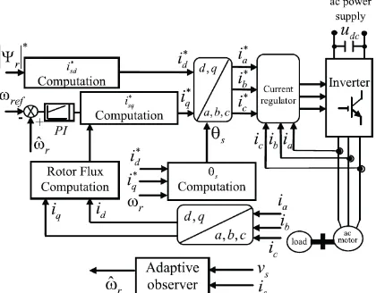
Figure 5: Basic FOC of Sensor less Induction Motor Drive
Here, only the rotor-flux-oriented type of control, also termed ”Field-Oriented Control” (FOC), is considered. FOC can be implemented as indirect (feed forward) or direct (feedback) depending on the method used for rotor flux identification. The direct FOC determines the orientation of the air-gap flux by use of a hall-effect sensor, search coil or other measurement techniques. However, using sensors is expensive because special modifications of the motor are required for placing the flux sensors. Furthermore, it is not possible to directly sense the rotor flux. Calculating the rotor flux from a directly sensed signal may result in inaccuracies at low speed due to the dominance of stator resistance voltage drop in the stator voltage equation and inaccuracies due to variations on flux level and temperature. In FOC, to perform the frame transformation, accurate rotor flux position is needed to be acquired.
Because with inaccurate rotor flux position torque and flux components are not be completely decoupled, as a result of which dynamic response become poor . So, knowledge of rotor flux position is the core of the FOC. The measurement of the rotor flux position is different if we consider synchronous or induction motor. In synchronous machine the rotor speed and rotor flux speed are equal. Then rotor flux position is directly measured by position sensor or by integration of rotor speed. In the induction machine the rotor speed is not equal to the rotor flux speed, then it needs a particular method to calculate field angle.
2.C. Comparison with direct vector control
The major disadvantage of direct vector method is the need of so many sensors. Fixing so many sensors in a machine is a tedious work as well as costlier. Due to this the scheme is prevented from being used. Several other problems like drift because of temperature, poor flux sensing at lower speeds also persists. Due to these disadvantages and some more related ones, indirect vector control is used. In indirect vector control technique, the rotor position is calculated from the speed feedback signal of the motor. This technique eliminates most of the problems, which are associated with the flux sensors as they are absent.
2.D. Advantages of Indirect FOC
The sensors are eliminated.
The dynamic performance of the indirect vector control is better than the direct vector control
The cost factor is decreased.
2.E. Advantages of Field Oriented Control
Improved torque response.
Torque control at low frequencies and low speed.
Dynamic speed accuracy. Four quadrant operation. Short-term overload capability. Reduction in size of motor, cost Reduction in power consumption .
3. SUMMARY
The stator currents are converted to a fictitious synchronously rotating reference frame aligned with the flux vector and are transformed back to the stator frame before feeding back to the machine. The indirect method is normally preferred over the direct method. It provides the independent control of flux and torque, control characteristics is linearised.
The vector control implementation with corresponding feedback signal estimation is complex, and therefore, digital control with high speed, powerful microcontroller, or DSP is essential. It is expected that the vector control will eventually emerge as the industry standard control method for induction motor drives. Fuzzy logic and neural network based adaptive controls constitute emerging technologies.
4. CONCLUSION
From the above discussion it can be concluded that the control of induction motor is very necessary as it is the common motor used in industrial motor control systems. Hence a well established induction motor drive which is simple, rugged, low cost and low maintenance can serve the required purpose. This paper reviews the various aspects in the field oriented control of induction motor including the principles, classification (direct and indirect FOC), and the flux vector position determination. Many authors have published several research papers on the vector control techniques of induction motor. And studying vector control techniques it is clear that the indirect vector control technique supersedes the direct vector control and is more used rather than the later one. Hence for the further work the method adopted is the indirect vector control technique.
5. REFERENCES
1. Domenico Casade, Francesco Profum, Giovanni Serra, Angelo Tani, “FOC and DTC: Two Viable Schemes for
Induction Motors Torque Control”, IEEE
TRANSACTIONS ON POWER ELECTRONICS, VOL. 17, NO. 5, SEPTEMBER 2002
2. Mircea Popescu, “INDUCTION MOTOR MODELLING
FOR VECTOR CONTROL PURPOSE”, Helsinki University of Technology, Laboratory of Electromechanics Report, Espoo 2000, 144 p.
3. Rakesh Singh Lodhi1, Payal Thaku, “Performance & Comparison Analysis of Indirect Vector Control of Three Phase Induction Motor”, International Journal of Emerging Technology and Advanced Engineering Volume 3, Issue 10, October 2013
4. Ashish Chourasia, Vishal Srivastava,Abhishek Choudhary and Sakshi Praliya, “Comparison study of Vector Control of Induction Motor Using Rotor Flux Estimation by Two Different Method”, International Journal of Electronic and Electrical Engineering, Volume 7, Number 3 (2014), pp. 201-206
5. Muhammad H. Rashid, “Power Electronics, Circuits, Devices and Applications”, Third edition 2011
6. B.SrinuNaik,“ComparisonofDirectandIndirectVector Control of Induction Motor”, International Journal of New Technologies in Science and Engineering Vol. 1, Issue. 1, Jan. 2014,
7. Bimal K Bose, “ Modern Power Electronics and AC Drives”, 2002,