311 | P a g e
SEISMIC BEHAVIOUR OF ELEVATED STORAGE
RESERVOIR BY FINITE ELEMENT METHOD
Suyash Nerkar
1, Chittaranjan Nayak
21
Student, M.E. Structural Engineering, VPCOE Baramati
2
Assistant Professor, Civil Engineering Dept, VPCOE Baramati
ABSTRACT
The elevated water tank consists of tank supported by staging system composed of columns, braces and
foundations. Elevated water tanks have generally performed well in seismic zones. However large number of
tank collapses has been observed during earthquakes from, as early as the San Francisco earthquake (1906) to
the Bhuj earthquake (2001). The observed damage in recent earthquakes shows that, it is necessary to choose
new methods for improvement while designing the structures. In many earthquake prone countries, buildings as
well as water tanks are continuously being retrofitted or constructed with control devices to reduce stresses,
displacements and base shear during seismic activity. A good understanding of the seismic behaviour of these
structures is necessary in order to meet up safety objectives while containing construction and maintenance
costs.
In this paper, circular and rectangular elevated water tank with different water levels are considered for study.
The static and dynamic analyses of time history were performed on the tanks. The different cases depending on
water levels as 0%, 25%, 50%, 75%, and 100% were studied. In this project base shear variation, time period
for different mode shapes, time history for different earthquakes were calculated by using SAP2000.
Keywords:
Base shear, dynamic analysis, stresses, SAP 2000, time history.
I. INTRODUCTION
The Bhuj earthquake of 26 January, 2001 in Gujarat, India caused the major destruction of medium-rise and
high-rise structures. After this earthquake, many questions ascended about our professional practices, building
by-laws, construction materials, and education for civil engineers and architects. In addition to this current
Indian codes do not address the evaluation of seismic resistance of existing structure standard, which may not
have been designed for earthquake forces.
In light of these facts, it is necessary to seismically evaluate the structures with the present knowledge to avoid
the major destruction during the earthquakes in future. Seismic safety of liquid storage tanks is of considerable
importance because water storage tanks should remain functional in the post earthquake period to ensure potable
water supply to earthquake affected regions and to cater the need for fire fighting. Industrial liquid containing
tanks may contain highly toxic and inflammable liquids and these tanks should not lose their contents during the
earthquake. Liquid storage tanks are mainly of two types, ground supported tanks and elevated tanks. Elevated
tanks are mainly used for water supply schemes and they could be supported on RCC shaft, RCC or steel frame,
312 | P a g e
II. METHODOLOGY
Design of new tanks and safety evaluation of existing tanks should be carried out with a high level of accuracy
because the failure of such structures, particularly during an earthquake, may be disastrous. In order to make
sure that the water tank design is capable to withstand any earthquake loads like overturning moment and base
shear, therefore the needs of detailed investigation of fluid structure interaction must be taken into account. The
movement and response of the water towards the wall structure may create an effect to the fundamental
frequency of elevated tank. There are many techniques to handle the dynamic response of elevated concrete
water reservoir. Most elevated tanks are never completely filled with liquid. Hence a two-mass idealization of
the tank is more appropriate as compared to a one mass idealization, which was used in IS 1893: 1984. Two
mass model for elevated tank was proposed by [Housner 1] and is being commonly used in most of the
international codes.
The number of elements should be such as to capture the variation of stiffness and mass of system. A minimum
of five beam elements should in general be sufficient. For axisymmetric finite elements shall be used. The
column elements for structure varying as the shape of container varies but the capacity of reservoir is same
throughout.
The study is carried out on reinforced concrete reservoirs. Elevated reservoir was modeled as having fixed base
in absence of soil structure interaction. The elevated reservoir with varying shapes with different water levels is
analyzed.
The work presented in the paper is directed towards analyzing the elevated reservoir by finite element method, as
it is most efficient method available today for analysis. This method can be used for analysis of having any
combinations and type of loading. Taking into account these facts, the following objectives have been put
forward.
1] To compare the static and dynamic response of elevated reservoir.
2] To develop the dynamic analysis is nothing but elaboration of first objective. The elevated reservoirs are
analyzed for dynamic time history analysis for Bhuj earthquake for changing geometry of reservoir such as
circular and rectangular.
3] After verification of results, nonlinear dynamic analysis of elevated service reservoir by time history method
procedure is carried out by using SAP2000 V16.2.4, for ascertaining the seismic capacity of structure by
considering changes in water levels such as for tank empty condition, 25%, 50%, 75% water levels, for tank full
condition.
III. STRUCTURE DESCRIPTION
Elevated reinforced concrete water tanks of both circular and rectangular shaped having same capacity of water
are to be analyzed. The tank is located in Pune district which is having ordinary moment resisting frame. The
height of container is 5.2m up to slab top of container. For circular shape diameter is 28m. The staging of
structure contains 49 No. of columns of 550 mm dia. Also braces top to top are 4 m. Find out the behaviour of
tank for different water levels and for different shapes such as circular and rectangular. Also compare between
313 | P a g e
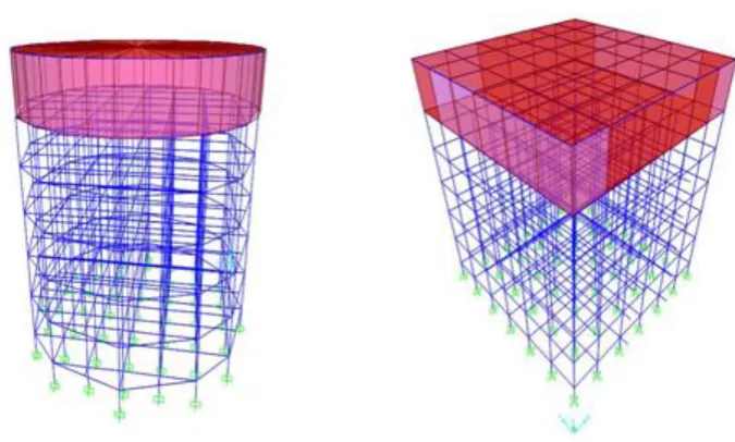
satisfy. Time history for Bhuj earthquake is considered. Time history data for Bhuj earthquake is applied to theparticular structure. Fig. 1 shows the view of elevated circular and rectangular reservoir. Both the reservoirs have
same capacity of water present in it. The following fig. 1 shows the 3D view of elevated reservoirs.
1. Grade of concrete is M 25.
2. Grade of steel is Fe 500.
3. Density of concrete is 25 kN/m3.
Figure 1 View of elevated circular and rectangular reservoir
IV. RESULTS
CASE I – Analysis of elevated circular reservoir
In this case I, analysis of elevated circular reservoir is carried out. There are five cases in case I which are
varying on water level in the reservoir. The base shear variation for each case for time history is described. The
ground motion data selected for time history analysis for Bhuj earthquake.
314 | P a g e
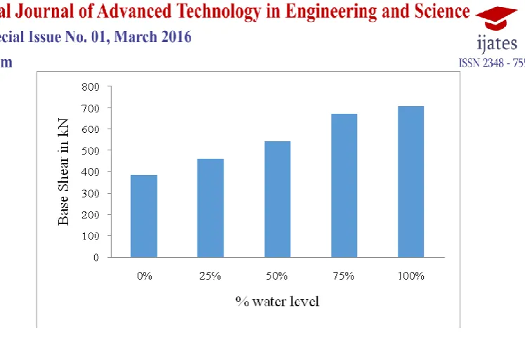
It is observed from fig. 2, that maximum base shear for elevated circular reservoir for time history analysis.Figure shows % of water level on x direction. The maximum base shear of every water level increases on an
average 10-15 % from 0 to 100 at every 25% water level.
Case I - Time period for different mode shapes for elevated circular reservoir
For elevated circular reservoir time period for different mode shapes at different water level is discussed.
Where mode shapes are on x axis while time period on y axis.
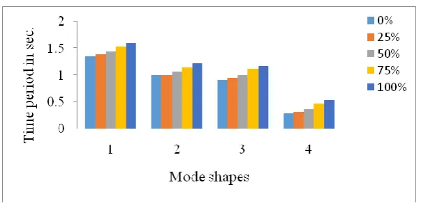
Figure 3 Comparison of time period for different water levels
The above fig. 3 shows the graph for time period variation in seconds on y- axis, while number of mode shapes
with respect to percentage of water level on x- axis. The figure shows for mode shape 1 gives values for time
period for all water levels. For first mode time period for full water level is increases by 18.75% than water
empty condition. Also for mode 2, time period for tank full condition is increases by 17.27% than tank empty
condition.
Case I - Comparison of displacement for elevated circular reservoir for tank empty and full
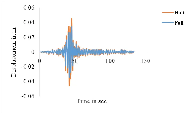
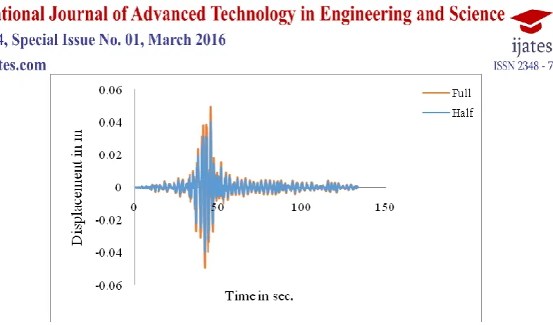
The figure 4 shows the comparison of displacement for reservoir full and empty condition
Figure 4 Comparison of displacement for reservoir full and empty case
It is observed from figure 4, that the time history graph for displacement with respect to time. The graph shows
displacement on y axis while time on x axis. The figure shows difference of displacement between reservoir full
and empty condition. The maximum displacement for tank full case is 4.5 cm while maximum displacement for
tank empty case is 2.2 cm. The difference in displacement between tank full and tank empty conditions is
48.88%.
315 | P a g e
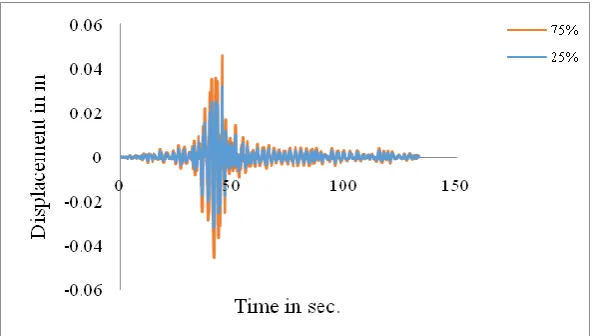
Figure 5 Comparison of displacement for reservoir 25% and 75% full case
It is observed from figure 5 that the comparison of displacement for reservoir 25% and 75% full cases. The
displacement for tank 25% full case is maximum by 30.95% than that of tank 75 % full case.
Comparison of displacement for reservoir 50% and reservoir full case-
Figure 6 Comparison of displacement for reservoir 50% and 100% full case
The figure 6 shows displacement in meter on y axis while time in seconds on x axis. The maximum
displacement for reservoir full case is 4.5 cm while the maximum displacement for reservoir 50% full case is 3.4
cm. The displacement for reservoir full case is maximum by 24.44% than that of tank 50% full case.
CASE II – Analysis of elevated rectangular reservoir
In this case II, analysis of elevated rectangular reservoir is carried out. There are five cases in case I which are
varying on water level in the reservoir. The ground motion data selected for time history analysis for Bhuj
earthquake.
316 | P a g e
Figure 7 Comparison of combined maximum base shear
It is observed from figure 7 that maximum base shear for elevated rectangular reservoir for time history
analysis. Figure shows % of water level on x direction and base shear in kN on y axis. The maximum base shear
of every water level increases on an average 20 % from 0 to 100 at every 25% water level. The value of
maximum base shear for tank empty condition is less than 45.46% than that of tank full condition.
Case II - Time period for different mode shapes for elevated rectangular reservoir
For elevated rectangular reservoir time period for different mode shapes at different water level is discussed.
Where mode shapes are on x axis while time period on y axis.
Figure 8 Comparison of time period for different water levels
It is observed from figure 8 that the mode shape 1 gives values for time period for all water levels. For first mode
time period for full water level is increases by 11.90% than water empty condition. Also for mode 2, time period
for tank full condition is increases by 12.81% than tank empty condition.
Case – II Comparison of displacement for elevated rectangular reservoir
317 | P a g e
Figure 9 Comparison of displacement for reservoir full and empty condition
It is observed from figure 9 time history graph for displacement with respect to time. The graph shows
displacement on y axis while time on x axis. The figure shows difference of displacement between reservoir full
and empty condition. The maximum displacement for tank full case is 4.9 cm while maximum displacement for
tank empty case is 2.5 cm.
Displacement for reservoir 25% and 75% full case-
The figure 10 shows the comparison of displacements in tank 25% and 50% full water levels.
Figure 10 Comparison of displacement for reservoir 25% and 75% full case
It is observed from figure 10, comparison of displacement for reservoir 25% and 75% full cases. The
displacement for tank 25% full case is maximum by 31.11% than that of tank 75 % full case.
Displacement for reservoir 50% and reservoir full case-
318 | P a g e
Figure 11 Comparison of displacement for reservoir 50% and 100% full case
It is observed from figure 11 that displacement in meter on y axis while time in seconds on x axis. The
maximum displacement for reservoir full case is 4.9 cm while the maximum displacement for reservoir 50% full
case is 3.9 cm. The displacement for reservoir full case is maximum by 20.40% than that of tank 50% full case.
V. CONCLUSION
1. From base shear variation with respect to time for time history for Bhuj, it is concluded that as water level
increases base shear for tank is also increases. By considering the geometry of tank as capacity of both circular
and rectangular tank is same the base shear for circular reservoir is more than rectangular reservoir for every
water level.
2. From combined results of time period variation for rectangular reservoir it is observed that, time period
variation for 100% filled water level is greater than 0% water level. As water level increases time period for
respective reservoir increases.
3. From the displacement of circular tank it is observed that, for reservoir empty condition displacement is
minimum while for full reservoir displacement is maximum. Displacement for circular reservoir is minimum
than that of rectangular reservoir.
4. Combined comparison of time period variation with mode shapes can be done in circular as well as
rectangular reservoir for considering all water levels as 0%, 25%, 50%, 75%, 100%. From which we observed
that time period variation in rectangular reservoir is maximum than time period variation in circular reservoir.
From graphs it is observed that as water level in the reservoir increases time period also increases.
REFERENCES
1. George W. Housner (1963), “ The Dynamic Behavior of Water Tank”, Bulletin of the Seismological
Society of America. Vol. 53, No. 2, pp. 381-387.
2. Sonoble Y. and Nishikawa T. (1969), “Study On The Earthquake Proof Design Of The Elevated Water
Tanks”, proceedings of the 4th
World Conference On Earthquake Engineering, Santiago, Chile. Vol. 4, No.
319 | P a g e
3. Wozniak R.S. and Mitchell W.W., 1978, “Basis of seismic design provisions for welded steel oil storage
tanks”, American Petroleum Institute 43rd midyear meeting, session on Advances in Storage Tank Design,
Toronto, Canada. Vol. 68, No. 4, pp. 48-53.
4. Veletsos, A.. S., 1984, “Seismic response and design of liquid storage tanks”, Guidelines for the seismic
design of oil and gas pipeline systems, Technical Council on Lifeline Earthquake Engineering, ASCE,
N.Y. No. 2, pp. 443-461.
5. Malhotra, P. K., 2004, “Seismic analysis of FM approved suction tanks”, Draft copy, FM Global, USA.
Vol. 35, No. 6, pp. 245-257.
6. Whittaker D. and Jury D., 2000, “Seismic design loads for storage tanks”, 12th World Conference on
Earthquake Engineering, New Zealand. Vol. 24, Paper No. 2376, pp. 85-93.
7. Sudhir K Jain and Sajjad Sameer U.(1993), “A Review of Requirements in Indian Codes For a Seismic
Design of Elevated water Tanks” Vol. 23, No. 1, pp. 1-16.
8. O. R. Jaiswal, Durgesh C. Rai, and Sudhir K. Jain(2007), “Review of Seismic Codes on
Liquid-Containing Tanks”,Earthquake Spectra, Vol. 23, No. 1, pp. 239–260.
9. Gareane A.I. Algreane, S.A. Osman, Othman A. Karim and A. Kasa (2011), “Study the fluid structure
interaction due to dynamic response of elevated concrete water tank”, Australian Journal of Basic and
Applied Sciences, ISSN 1991-8178. Vol. 5, pp.1084-1087.
10. M. V. Waghmare, S.N. Madhekar (2013), “Behaviour of elevated water tank under sloshing effect,
International Journal of Advanced Technology in Civil Engineering, ISSN: 2231 –5721, Vol. 2, No.1,
pp.12-29.
11. Sekhar Chandra Dutta, Somnath Dutta, Rana Roy(2009), “Dynamic behavior of R/C elevated tanks with
soil structure interaction,” Elsevier Engineering structures 31 (2009) 2617-2625”.
12. Applied Technology Council 40 (ATC40), “Seismic evaluation and retrofit of concrete buildings”, Vol.1
and 2, Applied Technology Council, Redwood City, CA, USA, Report No. SSC 96-01, 1996.
13. FEMA 356, “Prestandard and commentary for the seismic rehabilitation of buildings”,American society of
civil engineers, Reston, Virginia, Nov.2000.
14. SAP2000 V14.2.4, “Integrated finite element analysis anddesign of structures basic analysis reference
manual”,Berkeley, CA, USA: Computers and structures INC, Aug. 2010.
15. C.V.R. Murthy,Sekhar Chandra Dutta, Sudhir K. Jain(1996), “Torsional failure of elevated water tanks:
The problem and some solutions, “Elsevier Science Ltd. Paper No. 287, 11th World conference on
Earthquake Engineering”.
16. Emad Nsieri, Yaron Offir, Alex Shohat(2014), “Seismic retrofit of exiting spherical tank using non linear
viscous dampers”, 2nd European conferencs on earthquake engineering and seismology, Istanbul. Vol. 24,
No. 5, pp. 1-11.
17. Atsushi Mori, Ryoichi Fujita, Kiyoshi Yasugi, Ryoji Isoyama, Yuichi Hayashi and Kenji Niwa, “ A
study on a seismic verification and retrofit methods for an elevated water tank against strong earthquakes”,
320 | P a g e
18. Gaikwad Madhukar V., Prof. Mangulkar Madhuri N., “Comparison Between Static And DynamicAnalysis Of Elevated Water Tank”, International Journal Of Civil Engg And Technology(IJCIET) vol
4,No. 3, pp. 12-29.
19. Priestley, M. J. N., et al., 1986, “Seismic design of storage tanks”, Recommendations of a study group of
the New Zealand National Society for Earthquake Engineering.
20. R. Livaoglu, A. Dogangun (2006), “Simplified seismic analysis procedures for elevated tanks considering