Operation Characteristics of Microwave Sources Based on
Slow-Wave Interactions in Rectangular Corrugations
Yuki TAKAMURA, Yusuke KAZAHARI, Hiroaki OE, Kazuo OGURA, Akira SUGAWARA
and Mafumi HIRATA
1)Graduate School of Science and Technology, Niigata University, Niigata 950-2181, Japan
1)Plasma Research Center, University of Tsukuba, Tsukuba 305-8577, Japan
(Received 16 November 2007/Accepted 27 March 2008)
Studies on slow-wave devices with a novel disk cathode and two types of rectangular corrugation are re-ported. The beam voltage is weakly relativistic, which is less than 100 kV. A disk cathode can generate a uni-formly distributed annular beam in the weakly relative region. Rectangular corrugation having the ratio of the corrugation width to the periodic length of 50 or 20% is used. Using the former, output powers of about 200 kW are obtained at around 100 kV. For the latter, the effect of slow cyclotron resonance is observed in the low-energy region of around 30 kV. Output powers of slow cyclotron masers are in the range of a few hundred W. The oper-ation mode of a slow cyclotron maser can be controlled between axisymmetric and nonaxisymmetric modes by changing the end condition of rectangular corrugation.
c
2008 The Japan Society of Plasma Science and Nuclear Fusion Research
Keywords: slow-wave device, weakly relativistic region, disk cathode, annular electron beam, rectangular cor-rugation
DOI: 10.1585/pfr.3.S1078
1. Introduction
Microwaves of about 1 GHz to above 100 GHz at moderate to high-power levels (dozens of kW to MW level) are required for widespread applications such as plasma heating, plasma diagnostics, telecommunication systems and radar systems. Slow-wave high-power microwave de-vices such as backward wave oscillators (BWOs) are can-didates for such generators. The slow-wave devices can be driven by an axially injected electron beam without the initial perpendicular velocity, and has been studied ex-tensively as a candidate for high- or moderate-power mi-crowave sources. In the slow-wave devices, a slow-wave structure (SWS) is used to reduce the phase velocity of the electromagnetic wave to the beam velocity. In order to increase the power handling capability and/or the oper-ating frequency, oversized SWSs have been used success-fully. The term “oversized” means that the diameterDof the SWS is larger than the free-space wavelengthλof the output electromagnetic wave by several times or more.
In Refs. [1, 2], the K-band and Q-band oversized BWOs operating in the weakly relativistic region of less than 100 kV are reported. Output power in the range of hundreds of kW is obtained using a sinusoidally corrugated SWS. However, their fabrications become very difficult for oversized SWSs. The sinusoidal corrugations are impor-tant in view of the discharge in the SWS by strong electric fields at an extremely high power or more of the GW. For the moderate power level of the MW or less, the discharge in the SWS may not be a serious problem. In order to
over-author’s e-mail: [email protected]
come the constructional difficulty of sinusoidal corruga-tion, an alternative shape of the SWS is used in this study, i.e., a rectangular shape. Rectangular corrugations can be fabricated more easily and accurately than sinusoidal cor-rugations. Beam interactions in a rectangular SWS become stronger than those in a sinusoidal SWS. In this study, we use two types of rectangularly corrugated SWSs for which the ratio of the corrugation width to the periodic length differs. The upper cut-offfrequency is about 25 GHz for both the SWSs. One has dispersion characteristics paral-lel to the sinusoidal SWS in Ref. [2], and the other has dispersion characteristics that can be newly realized using rectangular corrugation. We examine the operation char-acteristics of the slow-wave devices based on each SWS in the high-(around 100 kV) and low-beam energy region (around 30 kV). Moreover, we propose to use a novel disk cathode made of metal only [2]. It can generate a uni-formly distributed annular beam in the weakly relativistic region.
2. Cold Cathode
We use a cold cathode to obtain a beam with a high current density. It is very difficult to generate a uniformly distributed annular beam using cold cathodes, especially in the weakly relativistic region of less than 100 kV. In gen-eral, hollow cathodes have been used as cold cathodes in the relativistic slow-wave devices [3]. In the past, we have also used a hollow cathode. In order to obtain an annu-lar electron beam in the weakly relativistic region, a velvet
c
Fig. 1 The burn patterns of annular electron beam. Left-side is a pattern of 5-shot overlay for the hollow cathode with velvet at about 90 kV. Right-side is a pattern of 1-shot for the disk cathode without velvet about 80 kV.
band is stuck on the axsymmetric emitting edge [1]. The velvet functions as a dielectric fiber emitter. By adjusting the velvet, fairly uniform annular beams are obtained, as shown in Fig. 1. The beam shape is observed by the burn pattern on a thermally sensitive paper. The average radius of the annulus is nearly the same as the cathode diameter.
Recently, the uniformity of the beam was improved much more using a novel disk cathode [2]. The concept of disk cathodes was presented in Ref. [4], and was used in the relativistic region in Ref. [5]. It is easier to obtain a high-quality beam without any exacting adjustment of the shape using a disk cathode than a hollow cathode with velvet. Moreover, a disk cathode is tougher than a hollow cathode with a velvet band, and it can be produced easily and economically. In this paper, the disk cathode is tested in the weakly relativistic region. The burn pattern is shown in Fig. 1. The annular beam produced by the disk cathode is distributed more uniformly with a higher current density than the hollow cathode using the velvet. Any coating on the emission surface of cathode is not required, even in the weakly relativistic voltage less than 100 kV. In our exper-iments, the disk cathode operates well even around 50 kV. The average electric field between the cathode and anode is around 105/cm or less. The beam current is some hundred
amps with the current density in the range of 100 A/cm2or
more.
3. Rectangular SWS
The cylindrical SWS is periodically corrugated, as shown in Fig. 2. Dispersion characteristics of the SWS are determined by the average radiusR0, corrugation
ampli-tudeh, corrugation widthd, and periodic lengthz0. The
corrugation wave number is given byk0=2π/z0. The
dis-persion characteristics of the structure are controlled by changingR0,h,d, andz0.
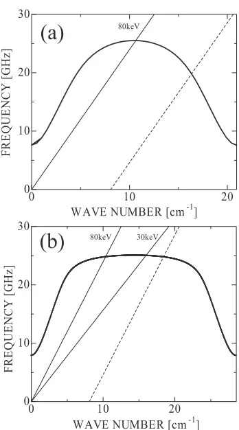
The dispersion curves of the rectangular SWS are ob-tained by a numerical method based on the mathematical formula in Ref. [6]. Figure 3 shows the dispersion relation of the axisymmetric transverse magnetic (TM01) mode for
type A and B, whose parameters are listed in Table 1. In
Fig. 2 Periodically corrugated cylindrical SWS.
Fig. 3 Dispersion characteristics of TM01for rectangular SWS, for type A (a) and type B (b). Solid and dashed lines are the beam line of space-charge mode and slow cyclotron mode, respectively.
Table 1 Parameters of rectangular SWS
R0[mm] h[mm] z0[mm] d/z0[%]
Type A 15.1 1.1 3 50
Type B 15.38 1.38 2.2 20
Fig. 3, the beam lines of the space-charge modeω = kzv
and slow cyclotron modeω = kzv−Ωare also plotted.
Here,ω,kz, v, andΩare the angular frequency, wave
num-ber, beam velocity, and relativistic cyclotron frequency, respectively. The slow space charge and slow cyclotron modes couple with the fundamental TM01 mode, leading
type A SWS shown in Fig. 3 (a), the slow-wave device op-erates as a BWO based on the Cherenkov instability using an 80 keV beam. The beam interaction point with TM01
is close to the upper cut-off atπ point. For the type B SWS shown in Fig. 3 (b), the dispersion curve around the upper cut-offbecomes flat compared with the type A. Also, the interaction point between the 80 keV slow space-charge mode and TM01mode shifts toward the traveling wave
re-gion. Decreasing the beam energy to 30 keV, the interac-tion point moves to a backward wave region. We examine the operation characteristics of the slow-wave device using each SWS in a high (around 100 kV) and a low (around 30 kV) energy region. It should be noted that the fabrica-tion of sinusoidal corrugafabrica-tion with a dispersion curve, like in Fig. 3 (b), is virtually impossible. The newly designed type B corrugation has a very flat upper cut-offregion of about 25 GHz. The frequency of the Cherenkov interaction point does not decrease, even for beams around 30 kV. Our aim is to investigate weakly relativistic slow-wave devices from such a low energy to 100 keV.
4. Experimental Results
The experimental setup is schematically shown in Fig. 4. An output voltage of up to 100 kV from the pulse forming line is applied to the cold cathode, which is the disk cathode proposed in Sec. 2. A uniform axial mag-netic fieldB0for the beam propagation is provided by ten
solenoid coils. The value ofB0can be changed from zero
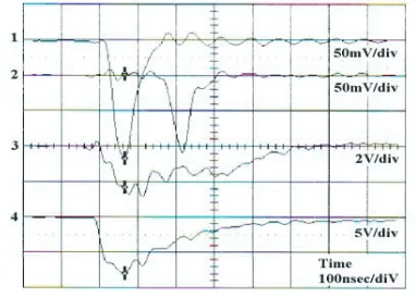
to about 0.9 T. The microwave outputs are picked up by a rectangular horn antenna, typically located 600 mm away from the output window. Adequate amount of signal at-tenuation in the detecting system is provided to protect the crystal detector. Figure 5 shows an example of the detected signals for the type A SWS. The beam voltage and current are about 100 kV and 300 A, respectively, at the microwave peak time.
The microwave signal is split into two branches us-ing a multi-hole directional coupler; one consists of a short waveguide and forms a prompt signal, and the other branch is a delay line and forms a delayed signal. The delay line is composed of a 31-m-long waveguide with a cutoff fre-quency of 17.4 GHz and a delay time is 152 ns. The op-eration frequency estimated from the delay time is about 26 GHz.
There exists a critical beam voltage for meaningful ra-diations [7]. The starting voltage is more critical than the starting current for the oversized BWOs. Figure 6 shows the dependence of the microwave power on the cathode voltage with type A SWS. The oscillation starting voltage is about 60 kV. The meaningful microwaves are not ob-served below this starting voltage. Output powers increase by increasing the cathode voltage above the starting volt-age. The vertical axis in Fig. 6 corresponds to microwave power picked up by the antenna. The estimated maximum radiation power is about 200 kW at around 100 kV.
Fig. 4 Schematic diagram of the experimental setup.
Fig. 5 Waveform of measured signals for type A SWS: 1 prompt signal, 2 delayed signal, 3 beam current signal and 4 beam voltage.
Fig. 6 Output powers versus the cathode voltage for a 10-period type A SWS.
For the type B SWS, the microwave output cannot be obtained in the energy region from 60 to 100 kV. However, microwave powers in the range of hundreds of W are ob-tained by adjusting the magnetic fieldB0 in a low-voltage
region around 30 kV. This voltage does not fulfill the os-cillation starting condition for the type B SWS. In Fig. 7, the power dependence onB0for the type B SWS is shown.
Fig. 7 Output powers versus the magnetic field for a 10-period type B SWS. The beam voltage is around 30 kV.
Fig. 8 Radiation patterns with the straight cylinder of (a) 34 mm and (b) 68 mm for type B SWS. (•) and () are respec-tivelyEθandEϕcomponents. Dashed curves are theoret-ical curves of (a) TM01and (b) HE11mode, respectively.
SWS, such an effect of the slow cyclotron interaction has not been observed in the low-voltage region with a voltage less than the oscillation starting voltage.
For our slow-wave device, both axisymmetric TM01
mode and nonaxisymmetric hybrid HE11 mode exist as a
candidate of the operation mode, as was studied based on the sinusoidally corrugated SWS case [1, 2, 8]. For deter-mining the operating mode experimentally, the radiation patterns are measured by moving the receiving horn an-tenna in an equatorial plane around a pivot at the center of the output window. The electric field components of
Eθ and Eϕ are measured by the horn antenna. Here, Eθ
(Eϕ) is the horizontal (vertical) component of the electric field in the equatorial plane. The pure TM01mode has no
Eϕ component. Also, the nonaxisymmetric hybrid HE11
mode consists predominantly of a nonaxisymmetric trans-verse electric TE11 component, and is characterized by a
peak at the center. Figure 8 shows the radiation patterns with the type B SWS. The beam voltage is about 30 kV. The magnetic field is 0.6 T near the peak of the output in Fig. 7. The radiation patterns are measured by changing the straight cylinder length before the SWS in Fig. 4. For a straight cylinder of 34 mm, the operation mode is domi-nated by the TM01mode, as can be seen from Fig. 8 (a). By
changing the straight length to 68 mm, the radiation pattern changes to the pattern HE11 mode, as shown in Fig. 8 (b).
The axisymmetric and nonaxisymmetric mode of the res-onance operation in Fig. 7 can be controlled by the axial condition of the SWS.
5. Discussion and Conclusion
We propose a novel cold cathode in the weakly rela-tivistic region, which is a disk-type cathode made of metal only. It can generate a uniformly distributed annular beam in the weakly relativistic region. We study weakly rela-tivistic slow-wave devices with the disk cathode and two types of the rectangular SWS. The estimated output power of about 200 kW is obtained by using the type A SWS at about 100 kV. This is an oversized BWO operation in the weakly relativistic region. However, the microwave by the oversized BWO operation is not observed in the high-energy region of around 100 kV for the type B SWS, be-cause the interacting point of the beam shifts to the trav-eling wave region. At about 30 kV, which does not fulfill the oscillation starting condition, radiations in the range of hundreds of W are obtained in a certain region of the mag-netic field.
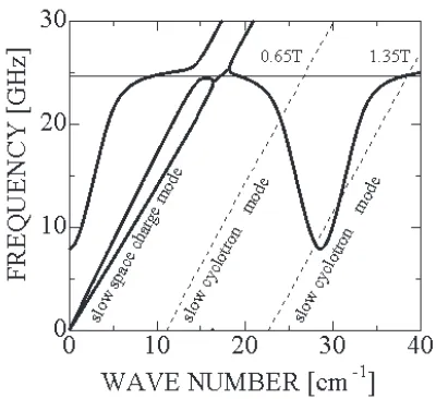
The dispersion characteristic of the TM01 mode for
the type B is shown in Fig. 9. Beam space-charge ef-fects are included in the interactions using a field theory based on an infinitesimally thin annular beam in Ref. [9]. The slow cyclotron mode depends on the axial magnetic fieldB0. By increasingB0, the beam line of the slow
cy-clotron modeω=kzv−Ωshifts to the right in Fig. 9. The
Cherenkov interaction synchronizes resonantly with the slow cyclotron interaction at the fundamental frequency with 1.35 T. This is a slow cyclotron maser operation, re-ported in Refs. [10, 11]. In our experiments, resonance oc-curs at around 0.65 T, which corresponds to the second har-monic of the slow cyclotron mode with 1.35 T. The output increase in Fig. 7 can be explained by a combined reso-nance operation of the Cherenkov interaction and the sec-ond harmonic slow cyclotron interaction. The slow cy-clotron maser operation mode can be controlled between the axisymmetric and nonaxisymmetric modes by chang-ing the end condition of the SWS.
Fig. 9 Dispersion curves of fundamental TM01for type B SWS. The beam energy is 30 keV.
interaction is effective for the second harmonic slow cy-clotron interaction. The operation of the slow cycy-clotron maser in the low-magnetic and low-energy regions is an important result, and the maser may prove to be a candi-date for a new type of useful microwave sources. More
definite study of the synergistic interaction is required for developing a new type of a microwave device.
Acknowledgments
This study was partially supported by a Grant-in-Aid for Scientific Research from the Ministry of Education, Science, Sports and Culture of Japan, and was partially performed under the Collaborative Research Program be-tween NIFS and University of Tsukuba in cooperation with Japanese universities.
[1] K. Oguraet al., IEEJ Trans. FM125, 733(2005). [2] S. Aoyamaet al., Trans. Fusion Sci. Tech.51, 325(2007). [3] G.A. Mesyats, Pulsed Power (Kluwer Academic/Plenum
Publishers, New York, 2005).
[4] O.T. Loza and P.E. Ivanov,Proc. 13th Int. Conf. High-Power Particle Beams, Nagaoka, Japan, pp.603-606 (2000). [5] K. Hanet al., IEEE Trans. Plasma Sci.30, 1112 (2002). [6] P.J. Clarricoats and A.D. Olver,Corrugated Horns for
Mi-crowave Antenna(Peter Peregrinus, London, 1984). [7] K. Ogura et at., J. Plasma Fusion Res. SERIES 6, 703
(2004).