TIME FREQUENCY TRAINING ESTIMATION METHOD OF OFDM FOR MOBILE LARGE
SCALE MIMO SYSTEMS
CH.Hasini 1*, P.Ratna Bhaskar2
1*SRK Institute of Technology,PG Scholar
2SRK Institute of Technology,Assistant Professor
*Correspondence Author: [email protected]
Keywords: large-scale MIMO, OFDM, spectral efficiency, time-frequency training (TFT), time frequency joint channel estimation.
Abstract
This overview portrays the 40 year evolution of orthogonal frequency division multiplexing (OFDM) research. the amelioration of powerful multicarrier OFDM arrangements with multiple- input multiple output(MIMO) systems has numerous benefits, this paper, we propose time frequency training OFDM(TFT OFDM) transmission scheme for large scale MIMO systems, where each TFT-OFDM symbol without cyclic prefix adopts the time-domain training sequence (TS) and the frequency-domain orthogonal grouped pilots as the time frequency training information We also derive the theoretical Cramer-Rao lower bound (CRLB) of the proposed channel estimator. Compared with conventional large-scale OFDM MIMO systems, we can also implement the MMSE method to improve the spectral efficiency.
Introduction
Fig.1. Time-frequency signal structure comparison: a) CP-OFDM MIMO with frequency-domain training information (pilots) only; b) The proposed TFT-OFDM MIMO with both time- and frequency-domain training information for every OFDM data block
Tft-ofdm system model
In this section, the time-frequency signal structure of the proposed TFT-OFDM MIMO scheme is described at first, and then the system model is presented.
Time-frequency signal structure of tft-ofdm
Fig. 1 compares the time-frequency signal structure of CPOFDM MIMO and the proposed TFT-OFDM MIMO. As shown in Fig. 1 (b), the TFT-OFDM signals are transmitted frame by frame, whereby each frame is composed of one preamble with its cyclic
extension and the following U TFTOFDM symbols (sub frames).We assume
N
ttransmit antennas andN
rreceive antennas inMIMO systems. In the time domain, unlike CP-OFDM where the CP is utilized as the guard interval, the ith TFT-OFDM symbol
( )p i
S
(1 ≤ i ≤ U) for the pth transmit antenna (1 ≤p ≤N
t) is composed of the length-N OFDM symbol Xi( )p [xi( ),0p ,xi( ),1p , ... xi N( ),p1]T and the followed length-MWhere . Since it has been proved in [1]. In the frequency domain, TFT-OFDM MIMO systems adopts G orthogonal
pilot groups randomly scattered within the signal bandwidth, where each pilot group has only one non-zero central pilot in the middle surrounded by d zero pilots on the left and right sides (in Fig. 1 (b), d = 1 is used as an example). Although frequency-domain pilots are common in OFDM systems, the proposed pilot pattern has the following four distinct features. [1].
System model of tft-ofdm mimo
In MIMO systems, for a certain receive antenna, the Channel impulse response (CIR)
h
i(p) associated with the pth transmit antenna during the ith TFT-OFDM symbol can be denoted by( ) (p) ( ) ( )
,0 ,1 , 1
[
,
,....,
]
p p p T
i i i i L
h
h
h
h
(2)Where
h
i l( ),p is the path gain of the lth path with the path delay
l(p) , L denotes the maximum channel spread, and L = M isassumed to avoid the interference between two neighboring OFDM data blocks, so we have
N
p
N M
t
N L
t . Note thatalthough the delay spread L maybe large in frequency selective channels, the number of most significant taps (or resolvable paths)
Q is usually much smaller than the channel length L, i.e., Q <<L, because of the sparse nature of wireless channels, especially for wideband communications.[1]. For example, the ITU
Vehicular B channel [1] with the maximum delay spread of 20 μs, which is equivalent to L = 200 samples at the system sampling
rate of 10 MHz, has only Q = 6 resolvable paths. Furthermore, it has been proved that the path delays
{
( )}
lL01p l
vary much slowerthan path gains
{
h
i(,lp)}
lL01 (including phases and amplitudes) [1] which is caused by the fact that the duration for the delay of a pathto change by one tap is inversely proportional to the signal bandwidth B, while the coherence time of the path gains is inversely
proportional to the carrier frequency
f
c. Since B <<f
cfor almost all of practical wireless systems, path delays would change muchslower than path gains. At the receiver, the signals coming from different transmit antennas will mix together, and the received
OFDM data block
y
i
[y , y
i,0 i,1,...,y
i N, 1]
T after cyclist reconstruction [1] is( ) ( ) 0 1
t
N
p p
i i i
p
y
x
h
w
(3)Where
W
i
[
w
i,0,
w
i,1,...,w
i N, 1]
Tdenotes the additive white Gaussian noise (AWGN) vector with zero mean and the variance of2 N
I
. Applying DFT toy
iabove, the received signaly
i.kon the kth subcarrier could be presented by( ) ( ) , , , , 1
0
1
t N p pi k i k i k i k
p
Y
X
W
W
k
N
(4)Where Hi( )p [H( )i,0p , Hi( ),1p , ...Hi N( ),p1]T is the channel frequency response (CFR) of
h
i( )p , and we have( ) ( )
,
p p
i N L i
H
N F
h
(5)Where
F
N L, of size N ×L denotes the first L columns of the DFT matrix FN. In addition, we useH
0( )P andh
0( )p to denote the CFRand CIR during the preamble, respectively.
Preamble based channel estimation:
Based on the preamble of the TFT-OFDM transmission frame, the initial channel estimation can be achieved either in the time or frequency domain. Their equivalence will be also proved in this section.
Time-domain channel estimation:
The received preamble
1
0
[
0,0,
0,1,....d
(0,NP]
Td
d
d
in the time domain at the receive antenna is immune from theinter-block-interference (IBI) due to the protection of the cyclic extension, so
d
0 can be expressed by(6)
In (6), there are
N
tL unknown parameters inh
0 andN
pobservations ind
0. IfN
p≥N
tL, the time-domain channel estimateh
0^can be obtained by [11]
0 0 1 0 0 0 0 ^
0
c
d
(
c
c
)
c
d
h
H H (7)We have
1 * 0 0 1 0 0 0 ^
0
}
{(
)
0
{
L N H H tv
c
c
c
E
h
h
E
due to every element ofv
0 has zero mean, so the mean square error (MSE) of theunbiased channel estimator (7) is
(8)
According to the proof in the Appendix[1], the minimum MSE can be achieved by the following optimal design criterion
(9) The corresponding MSE in (8) is then derived as
Thus, the minimum MSE (10) can be achieved, and the time-domain channel estimator (7) is then simplified by circular correlation [1] as
(11)
Frequency-domain channel estimation:
The frequency-domain signal model (4) is also valid when
N
p-point DFT instead of N-point DFT is used to produce the receivedpreamble
D
0
[
D
0,0,
D
0,1,...
D
0,
N
p1]
T in the frequency domain, i.e.,0 0 0
0
C
H
V
D
(12)Where
V
0
F
NPv
0 denotes AWGN,D
0
F
NPd
0presents theN
p-point DFT of the time-domain received preambled
0,0 ) 2 ( ) 1 (
0 [diag{C },diag{C },....,diag{C }]d
C Nt denotes the
p
N
×N
tN
pfrequency-domain training matrix based ont
N p p
C
( )}
1{
,and the CFR
H
0during the preamble can be related to the corresponding CIRh
0 by using (5) as0 0
0
F
h
H
, where(13)
Since there are
N
tN
punknown parameters inH
0 and onlyN
pobservations inD
0, eq. (12) is an underdetermined problemwithout unique solution. However, this problem can be solved by using the relationship between the CFR
H
0 and the CIRh
0 asbelow 0 0 0 0 0 0 0
0
C
F
h
V
A
h
V
D
(14)Where
A
0
C
0F
0 and the number of unknown parameters is reduced fromN
tN
p in (12) toN
tLin (14). IfN
p≥N
tL, thechannel estimation can be achieved by [1]
0 0 0 1 0 0 0 0 0 0 ^
0
A
D
((
C
F
)
C
F
)
(
C
F
)
D
h
H H (15)Then, the CFR can be obtained by
H
0^
F
0h
0^
F
0A
0D
0Unification of the time- and frequency-domain channel estimators:
The time-domain channel estimator (7) is based on time domain signals
d
0 andc
0, while the frequency-domain channel estimator(15) depends on the frequency-domain signals
D
0 andc
0. SinceD
0 (c
0) can be obtained onced
0 (c
0) is known, and vice versa,the time- and frequency-domain channel estimators (7) and (15) can be directly unified by the extracted DFT matrix F0 denoted by
(13). Regarding to the optimal design criterion, we have in Section III-A derived (9) for the time-domain training matrix
c
0 , while ithas been proved in [9] that the optimal frequency domain channel estimator (15) is subject to the following optimal design criterion
NtL t H
LI
N
A
A
0 0
(16) Using the well-known shift property of DFT, it can be derived that0 0 0
0
C
F
A
c
F
p
With the help of (17), the unification of the optimal design criteria (9) and (16) for the time- and frequency-domain channel estimators, respectively, can be revealed by
0 0 0 0
0 0
0
0C (F A) F A A (F F )A A A
C N NH H
H H
N H H N H
p p p
p
(18)
It reads clear from (18) that the different design criteria (9) and (16) are essentially equivalent. Therefore, the time- and frequency-domain channel estimators as well as their corresponding optimal design criteria can be unified under the same framework. Channel tracking and data detection in [1].
Performance analysis
This section addresses the performance analysis of the proposed scheme, including the spectral efficiency of proposed TFT-OFDM scheme, the CRLB as well as the computational complexity of the time-frequency joint channel estimation method.
Spectral efficiency:
The spectral efficiency
0 of the proposed TFT-OFDM MIMOcan be expressed in the percentage notation as
(19)
Where K = G ((2d+ 1) + (
N
t− 1) (d + 1))For large-scale 16 × 16 MIMO configuration, i.e.,
N
t=N
r = 16, the number of used pilots in TFT-OFDM is K = 160, which isonly 3.91% of the total subcarrier number N = 4096. Table I clearly indicates that the proposed TFT-OFDM MIMO scheme outperforms its conventional counterparts in spectral efficiency. Since every receive antenna could use the time-frequency joint channel estimation method to distinguish the channels between different transmit antennas and this specific receive antenna, the proposed TFT-OFDM transmission scheme could be used in both scenarios having small (even a single) or large number of receive antennas, and higherspectral efficiency than conventional solutions could be achieved in both cases.
Cramer-rao lower bound:
The CRLB bound is the theoretical bound to evaluate the performance of practical estimation methods [11].
Table1: Spectral Efficiency in MIMO Systems.
Since the AWGN vector
W
i(p)in [1] is subject to the Distribution of CN (0,
2I
G), the conditional probability density function(PDF) of
Y
i(p) with the givenh
i(,p) is(21)
Where
h
i(,p,)mandh
i(,p),ndenotes the mth and nth entry ofh
i(,p), respectively. Finally, according to the vector estimation theory [11],the CRLB of the unbiased estimator ^( )
,
p
i
h
is(22)
Let
{
i}
Qi0 being the Q eigenvalues of the matrix PN H P
N
F
F
)
(
( ) , then, we have the following result according to the elementary linear algebra [1](23)
Where the equality holds if and only if λ1 = λ2 = ・・・=
Q, which means that the matrixF
N(P) extracted from the standard DFTmatrix
F
Nshould have orthogonal columns. Obviously, the Q×Q matrixP N H P
N
F
F
)
(
( ) has identical diagonals equal to G, i.e., Tr { PN H P
N
F
F
)
(
( ) } = GQ, so the CRLB of the proposed time-frequency joint channel estimator becomes(24)
Computational complexity:
The computational complexity of the proposed time frequency joint channel tracking scheme can be evaluated in terms of how many multiplications are required in [1].
Simulation result
Fig. 1 MSE performance comparison between the proposed time-frequency joint channel estimation method for TFT-OFDM with the conventional schemes.
In Fig. 1 the MSE performance of the proposed time-frequency joint channel estimation for TFTOFDM in large-scale MIMO systems over the Brazil D channel with the receiver velocity of 5 km/h. For comparison, we also include the MSE performance o f CP-OFDM with comb-type pilots and the time-domain preamble based iterative channel estimation/data detection scheme for large-scale MIMO systems [8]. In addition, the theoretical CRLB derived in (40) is also plotted as the benchmark for comparison. It is clear that TFT-
OFDM outperforms CP-OFDM and TDSOFDM by about 5 dB when the channel estimation MSE 10-2 is considered, and performs 3 dB better than
[8].
Also we could observe that the proposed channel estimation performs closely to the theoretical CRLB with a small SNR gap, which is caused by the fact that the “extracted” DFT matrix F (p)N has imperfect but approximate orthogonal columns.
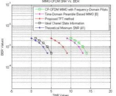
Fig. 2 BER performance comparison between the proposed TFT-OFDM MIMO scheme and its counterparts over the Vehicular B channel with the receiver velocity of 30 km/h.
Conclusions
Fig.3 MSE comparison between the least square method and minimum mean square method in TFT OFDM.
Fig.4 BER comparison between MMSE CE and LS CE in TFT ofdm.
And the subsequent TFT-OFDM symbols could provide efficient channel tracking and data detection in MIMO systems. This paper proves the unification of the time- and frequency-domain channel estimation based on them preamble, and derives CRLB of proposed time-frequency joint channel estimation. Simulation results indicate that the proposed scheme enjoys the BER
performance close to the theoretical ergodic capacity. The proposed TFT-OFDM MIMO scheme can be also directly applied in multiple access systems in both the uplink and downlink, and the principle of joint time-frequency processing behind TFT-OFDM can be adapted for other OFDM MIMO systems (including large- and small scale systems) to achieve higher spectral efficiency as well as more reliable performance over severe fading channels.
Acknowledgement
The first author would like to thank Prof. Feifei Gao for his valuable support for this paper. The authors would like to thank the Guest Editor and the anonymous reviewers for their helpful comments and suggestions to improve the quality of this manuscript. Appendix proof of (15) and (16) in [11]
References
1. L. Dai, Z. Wang, and Z. Yang, “spectrally efficient time-frequency training OFDM for Mobile large scale MIMO systems”, IEEE Commun. Mag., vol. 31, no. 2, pp. 251–262, Feb. 2013.
2. L. Dai, Z. Wang, and Z. Yang, “Next-generation digital television terrestrial broadcasting systems: Key technologies and research trends,” IEEE Commun. Mag., vol. 50, no. 6, pp. 150–158, Jun. 2012.
4. IEEE Standard for Local and Metropolitan Area Networks Part 16: Air Interface for Broadband Wireless Access Systems. IEEE Standard802.16-2009, May 2009.
5. 3rd Generation Partnership Project; Technical Specification Group Radio Access Network; Evolved Universal Terrestrial Radio Access (EUTRA) and Evolved Universal Terrestrial Radio Access Network (EUTRAN); Overall description; Stage 2 (Release 8). 3GPP TS 36.300, V8.5.0, May 2008.
6. F. Rusek, D. Persson, B. K. Lau, E. G. Larsson, O. Edfors, F. Tufvesson, and T. L. Marzetta, “Scaling up MIMO: Opportunities and challenges with very large arrays,” IEEE Signal Process. Mag., 2012. (in press).
7. M. Matthaiou, N. Chatzidiamantis, and G. Karagiannidis, “A new lower bound on the ergodic capacity of distributed MIMO systems,” IEEESignal Process. Lett. vol. 18, no. 4, pp. 227–230, Apr. 2011.
8. S. K. Mohammed, A. Zaki, A. Chockalingam, and B. S. Rajan, “Highratespace–time coded large-MIMO systems: Low-complexity detection and channel estimation,” IEEE J. Sel. Topics Signal Process., vol. 3,no. 6, pp. 958–974, Dec. 2009. 9. H. Taoka and K. Higuchi, “Experiments on peak spectral efficiency of 50 bps/Hz with 12-by-12 MIMO multiplexing for future
broadband packet radio access,” in 4th IEEE International Symposium on Communications, Control and Signal Processing (ISCCSP’10), 2010, pp. 1–6.
10. G. Breit and et al., 802.11 ac Channel Modeling. IEEE 802.11 TGac: Very High Throughput below 6GHz Group doc. 09/0088, Jan. 2009.