VOLUME 2, ISSUE 5, May -2016
10 |
P a g e
HARMONICS REDUCTION WITH Id-Iq CONTROL STRATEGY
USING FUZZY LOGIC CONTROLLER BASED THREE PHASE
SHUNT ACTIVE POWER FILTER
Mr. ABHIJIT A. INGALE
Department of Electrical Engineering
MSS’s, College of Engineering and technology, Jalana, India
[email protected]
Prof. KOMPELLI SANTHOSH,
Head of Department, Electrical Engineering
MSS’s, College of Engineering and technology, Jalana, India
[email protected]
ABSTRACT:
Shunt active power filters found the application in elimination of current harmonics in power system. The performance of such filter depends upon various factors like control methods, inverter used, and reference current generation technique. In this paper the authors have implemented fuzzy logic control technique for generation of pulses of the three phase inverter. Harmonic extraction is mainly achieved by a band pass filter in synchronous reference frame algorithm (SRF) or Id-Iq theory. The performance of the shunt active power filter is evaluated with MATLAB/ SIMULINK under balanced voltage conditions. After evaluation authors have found that the harmonic elimination is achieved satisfactorily.
KEYWORDS: PI controller, Shunt active power filter, synchronous reference frame, voltage source converters, Pulse with modulation, fuzzy logic controller, linear and nonlinear loads.
I. INTRODUCTION
Power quality is greatly influenced by nonlinear loads i.e. power electronic equipment, electrical drives, welders, energy saving lamps, ovens etc., leads to injection of harmonics in distribution system. Disturbed power quality results improper function of devices, which leads in spurious tripping of protective devices, overheating of rotating machinery, etc. This problem can be solved by installation of power quality improvement devices [1-3]. For the mitigation of this power quality issue, passive power
filter is a traditional harmonic mitigation method. But it has certain disadvantage as it fails to eliminate all of the harmonics. It has the drawbacks including heavy weight, and bulky sizes, problem of series or parallel resonance with the system impedance, sensitivity against system parameter variation [3-6].
The important components while designing of any shunt active power filter is control strategy, inverter topology and current control method used in the generation of pulse for the inverter [7]. synchronous reference frame (SRF) theory or d-q theory [11-12] widely used in three phase system of extraction of reference current from the load harmonics current, due to its simplicity and easy implementation as compared other many methods. For obtaining good accuracy and dynamics in SRF method numerical filtering method play very important role. Fuzzy logic controller is proposed in this study for current control of the three phase voltage source inverter (VSI).
Under balanced voltage condition, the output performance of shunt active power filter is simulated with MATLAB/SIMULINK.
II. SHUNT ACTIVE POWER FILTER
VOLUME 2, ISSUE 5, May -2016
11 |
P a g e
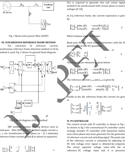
Fig. 1 Shunt active power filter (SAPF)
III. SYNCHRONOUS REFERENCE FRAME METHOD For extraction of reference current, Synchronous reference frame detection method or Id-Iq method is used. Fig. 2 shows its general block diagram.
Fig. 2 Block diagram of Id-Iq method
SRF method contains filtering devices such as band pass filter (BPF). In SRF method supply current ia,
ib, ic are transformed to two phase (α − β ) stationary
reference frame current iα and iβ as shown in equation1.
PLL is required to generate sine and cosine signals needed to be synchronised with various phase to neutral voltages [9-10].
In d-q reference frame, the current expression is given by;
Where θ phase angel of voltages.
Band pass filter is used convert harmonics with the DC quantities in to non-DC quantities.
Thus iα and iβ are obtained as given below:
The reference current iα-ref and iβ-ref is given by
Finally in the abc reference frame the current are given as
IV. PI CONTROLLER
VOLUME 2, ISSUE 5, May -2016
12 |
P a g e
Fig. 3 conventional PI controller
The average capacitor voltage is maintained at a constant value, by multiplying peak value of the current (Imax) and the unit sine vectors in phase with the respective source voltages to obtain the reference compensating currents. error signal for the modulation technique is evaluated by comparing estimated reference currents and the actual sensed compensating current in a hysteresis limiter.
V. FUZZY LOGIC CONTROLLER
Fuzzy logic technique gives an improved performance of switching pulse for voltage source inverter than PI controller. Fuzzy control depends on logical system that involves the set of simple linguistic rules called fuzzy logic for the determination of control action [8]. The internal control circuit with fuzzy controller is shown in fig 4. It consist of two inputs [11, 12] namely error (e) and change in error (Δe) and one output.
Fig. 4 control circuit with fuzzy controller
The error signal is the difference between current Iref and actual current Iinv of VSI for each phase.
Error=Iinv-Iref 7
The error signal is processed through a Fuzzy controller, which helps to gain zero steady error in tracking the
reference current signal. Input voltage Vdc which is proportional to actual current of VSI and the input reference voltage Vdc-ref which is proportional to reference current are given to differentiate block as a input variables of the fuzzy logic controller. Then the output variable of the fuzzy logic controller is presented by the Current limiter. To convert these numerical variables into linguistic variables, the following seven fuzzy levels or sets are chosen as:
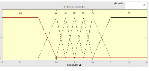
NB (negative big), NM (negative medium), NS (negative small), ZE (zero), PS (positive small), PM (positive medium), and PB (positive big) as shown in fig 5. The fuzzy controller is characterized as follows:
1. Seven fuzzy sets for each input and output; 2. Fuzzification using continuous universe of discourse;
3. Implication using Mamdani's ‘min’ operator; 4. De-Fuzzification using the ‘centroid’ method.
Fuzzification: the process of converting a numerical variable (real number) convert to a linguistic variable (fuzzy number) is called Fuzzification.
Fig. 5. a) Input Variable Error ‘E’ Membership Function using Id-Iq Theory
VOLUME 2, ISSUE 5, May -2016
13 |
P a g e
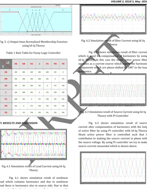
Fig. 5. c) Output Imax Normalized Membership Function using Id-Iq Theory
Table 1 Rule Table for Fuzzy Logic Controller
VI. RESULTS AND DISCUSSION
Fig. 6.1 Simulation result of Load Current using Id-Iq Theory
Fig. 6.1 shows simulation result of nonlinear load which contains harmonics and due to nonlinear load there is harmonics also in source side. Due to that harmonic, distortion in current waveform on source side and system is not stable
Fig. 6.2 Simulation result of filter Current using Id-Iq Theory
Fig. 6.2 shows simulation result of filter current which is used for compensation of harmonics by using Id-Iq Theory. In this case the shunt active power filter operates as a current source which injects the harmonic components which are phase-shifted by 180° to the load harmonics.
Fig. 6.3 Simulation result of Source Current using Id-Iq Theory with PI Controller
Fig. 6.3 shows simulation result of source current after compensation of harmonics with the help of active filter by using PI controller with Id-Iq Theory. Shunt active power filter is controlled such that it contributes to making the source current in phase with the source voltage. By using PI controller we try to make source current sinusoidal which is shown above.
VOLUME 2, ISSUE 5, May -2016
14 |
P a g e
Fig. 6.4 shows simulation result of source current after compensation of harmonics with the help of active filter by using fuzzy logic controller with Id-Iq theory. By using fuzzy logic controller we try to make source current sinusoidal and while we compare with PI controller fuzzy gives better response than PI controller which is shown above
Fig. 6.5 Simulation results of voltage across capacitor by using Id-Iq Theory with PI Controller
Fig. 6.5 shows simulation result of voltage across DC side capacitor during the compensation of harmonics with the help of Shunt active power filter by using PI controller with Id-Iq Theory. In this case, system gives oscillatory behaviour during transient period i.e. at starting and settles down after specific time.
Fig. 6.6 Simulation results of voltage across capacitor by using Id-Iq Theory with Fuzzy Logic Controller
Fig. 6.6 shows simulation result of voltage across DC side capacitor during the compensation of harmonics with the help of Shunt active power active filter by using Fuzzy logic controller with Id-Iq Theory. In this case, system produces less oscillation at starting and settles down within short period as compared to PI controller. Steady state response using Fuzzy logic controller is better as compared to PI controller.
Fig. 6.7 Simulation results of FFT Analysis to show Total Harmonic Distortion by using Id-Iq Theory with PI
Controller
Fig. 6.7 shows simulation FFT window by using PI controller with Id-Iq Theory and showing %THD is 1.70.
Fig. 6.8 Simulation results of FFT Analysis to show Total Harmonic Distortion by using Id-Iq Theory with Fuzzy
Logic Controller
Fig. 6.8 shows simulation FFT window by using fuzzy logic controller with Id-Iq Theory and showing %THD is 1.75.
Table 2 Comparison of PI and Fuzzy Logic Controller
Sr.
No. Parameter
PI Controller
Fuzzy Logic Controller
1 Transient
Response Good Better
2 Undershoot
and overshoot More Less
3 Steady State
Response Good Better
4 % Error Less
Slightly less than PI Controller
5 Load current Same Same
VOLUME 2, ISSUE 5, May -2016
15 |
P a g e
VII CONCLUSION
This paper presents an overview of Instantaneous Power and Current Strategies for Current Harmonics Cancellation using Shunt Active Power Filter with PI and fuzzy logic controllers. The controllers PI and fuzzy logic under balanced, unbalanced, non-sinusoidal control has to be validated for Shunt Active Power Filter (SAPF).Comparison of controllers with PI and fuzzy logic will be made based on certain performance parameters.
VIII REFERENCES
[1] S.Khalid & Bharti D wivedi, “Power Quality Issues,
Problems, and Standards”, IEEE transactions on power quality, May 2011, vol.1, no.2, page no.09 to 16
[2] Nitin Gupta and S. P. Singh, “Fuzzy logic controlled
shunt active power filter for reactive power compensation and harmonic elimination”, IEEE transaction, May 2011, vol. 1, page no. 82 to 87.
[3] HamisuUsman, Hashim Hizam,“Simulation of
Single-Phase Shunt Active Power Filter with Fuzzy Logic Controller for Power Quality Improvement”, IEEE conference on clean energy and technology, Feb 2013, vol.1, page no 353 to 357.
[4] Suresh Mikkili and Anup Kumar Panda, “PI and
Fuzzy Logic Controller Based 3-Phase4-Wire Shunt Active Filters for the Mitigation of Current Harmonics with the Id-Iq Control Strategy”, Journal of Power Electronics, November 2011, vol. 11, no.06, page no. 914 to 921.
[5] Suresh Mikkili, Anup Kumar Panda, “Instantaneous
Active and Reactive Power and Current Strategies for Current Harmonics Cancellation in 3-ph 4-Wire SHAF with Both PI and Fuzzy Controllers”, IEEE transaction on Energy and Power Engineering, July 2011, vol. 3, page no. 285 to 298
[6] Bruno Exposto, “Current-Source Shunt Active Power
Filter with Periodic-Sampling Modulation Technique” IEEE transaction on active power filter Dec 2012, vol. 1, no.2, page no.1274 to 1279
[7] Karuppanan P, Kamala Kanta Mahapatra, “PI and
fuzzy logic controllers for shunt active power filter”, ISA transaction, March 2011, page no. 163 to 169
[8] Anup Kumar Panda, Suresh Mikkili, “FLC based shunt
active filter (p–q and Id–Iq) control strategies for mitigation of harmonics with different fuzzy MFs using MATLAB and real-time digital simulator”, January 2012, page no. 313 to 336
[9] Md. Ashfanoor Kabir and Upal Mahbub,
“Synchronous Detection and Digital control of Shunt Active Power Filter in Power Quality Improvement” IEEE transaction on power quality, Nov 2011
[10] Rejil C and Arun Kumar, “Design and Simulation of
three phase shunt active power filter using synchronous reference frame (SRF) theory” IEEE transaction on shunt active power filter, vol 3, no. 6, page no. 651 to 660
[11]Jivan B. Patil, Chinala Mallareddy, (2015),
“Instantaneous Power and Current Strategies for Current Harmonics Cancellation Using Shunt Active Power Filter With PI and Fuzzy Logic Controllers” Published in ICIEEE-15. International Conference on Industrial Electrical and Electronics Engineering, Pune, India, 10th May, 2015.
[12]Jivan B. Patil, Chinala Mallareddy, Sharad B. Bhosale,