Ashwini et al. World Journal of Engineering Research and Technology
COMPARATIVE STUDY OF DIFFERENT TYPES OF END CLOSURES
USED IN HORIZONTAL PRESSURE VESSELS AND ITS EFFECT ON
STRESS LEVELS IN PRESSURE VESSEL AND SADDLE SUPPORT
Rohit Jadhav*1, M. N. Mathapti2 and Sanket Bhosale3
1,2,3
Asst. Prof., DepartmentOf Production Engineering, D. Y. Patil College of Engineering,
Akurdi, Pune-411 044, Maharashtra, India.
Article Received on 25/10/2017 Article Revised on 15/11/2017 Article Accepted on 06/12/2017
ABSTRACT
Different end closures or head ends are used in pressure vessels which
are subjected to different pressure conditions. Most of the pressure
vessels are designed according to ASME code as per zicks theory, but
this theory has used horizontal pressure vessel as simply supported
beam but this assumption do not consider the effect of change in size
and shape of the vessel head ends. In this work comparative study of
different end closures hemispherical head, Flat head & Semi –
ellipsoidal is discussed. Design by Analysis Approach using FEA software ANSYS is used to
observe the level of stresses at mid span of horizontal pressure vessels & saddle support to
find out the optimum pressure vessel end closure type.
KEYWORDS: Zicks Theory, FEA, Saddle, end-closure, hemispherical head, flat head, semi-ellipsoidal head.
1.INTRODUCTION
1.1. End Closures in Pressure Vessels: A pressure vessel is a closed container designed to hold gases or liquids under internal or external pressure. Pressure vessels are designed to
operate safely at a specific pressure and temperature. End closures or head ends are used in
pressure vessels which are subjected to different pressure conditions. Different types of head
World Journal of Engineering Research and Technology
WJERT
www.wjert.org
SJIF Impact Factor: 4.326*Corresponding Author Rohit Jadhav
Asst. Prof., Departmentof
Production Engineering, D.
Y. Patil College of
Engineering, Akurdi,
Pune-411 044, Maharashtra,
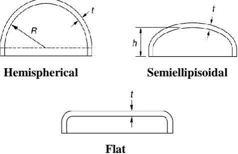
ends which are use in pressure vessels are hemispherical head, Flat head, Semi –ellipsoidal &
Torispherical Heads.
Fig. 1: Horizontal Pressure Vessel.
1.2. Types of End Closures or Head ends: Heads are one of the important parts in pressure vessels and refer to the parts of the vessel that confine the shell from below, above, and the
sides. The ends of the vessels are closed by means of heads before putting them into
operation. The heads are normally made from the same material as the shell and may be
welded to the shell itself. They also may be integral with the shell in forged or cast
construction. The head geometrical design is dependent on the geometry of the shell as well
as other design parameters such as operating temperature and Pressure. The geometry of the
head is selected based on the function as well as on economic considerations, and methods of
forming and space requirements. The elliptical and torispherical heads are most commonly
used. The carbon steel hemispherical heads are not so economical because of the high
manufacturing costs associated with them. They are thinner than the cylindrical shell to
which they are attached, and require a smooth transition between the two to avoid stress
concentration effects. The thickness values of the elliptical and torispherical heads are
typically the same as the cylindrical shell sections to which they are attached.
Hemispherical Semiellipisoidal
Flat
1.3. Design by Analysis (DBA) Methodology using ANSYS Parameters
Design pressure P= 200psi
Saddle width b= 12in
Load per saddle Q=300,000lb
Saddle angle of contact θ=120°
Outside radius of shell R=6in
Shell thickness ts=1in
Length of vessel of tangent to tangent line L=60in
Depth of dish of head H=6in
Distance from tangent line of head to centre of saddle A=2.5inch
2. METHODOLOGY
The entire CAD model of the pressure vessel with saddle support is modeled in FEA software
ANSYS as shown in below Fig 4. The CAD model prepared in ANSYS is meshed by using
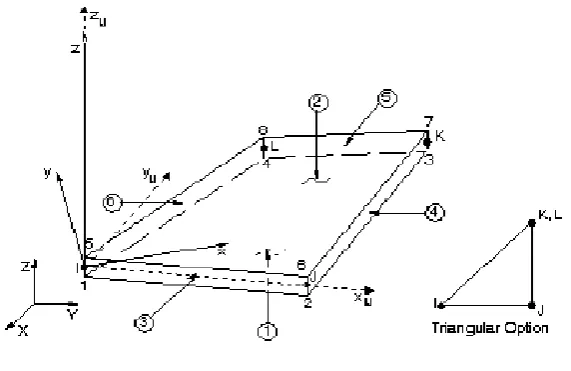
SHELL 63 as shown in below Fig 5. SHELL63 as shown in Fig 3 has both bending and
membrane capabilities. Both in-plane and normal loads are permitted. The element has six
degrees of freedom at each node: translations in the nodal x, y, and z directions and rotations
about the nodal x, y, and z-axes. Stress stiffening and large deflection capabilities are
included. A consistent tangent stiffness matrix option is available for use in large deflection
(finite rotation) analyses.
Fig. 4: CAD model.
Fig. 5: Meshed model using shell 63.
3.2. Boundry Conditions and application of load
The boundary conditions applied are both saddles were made fixed and internal pressure was
apllied to the vessel and the analysis was performed to see the stresses in saddle and in the
vessel. For meshing the model we have used mesh size that is element size as 5.
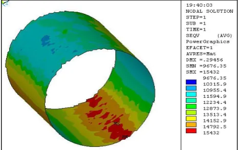
3. RESULTS AND DISCUSSION 3.1. Case I:- hemispherical end
Fig. 7: Equivalent stress in saddle for hemispherical end.
3.2. Case II:- Semiellipisoidal end
Fig. 8: Equivalent stress in vessel for semiellipisoidal end.
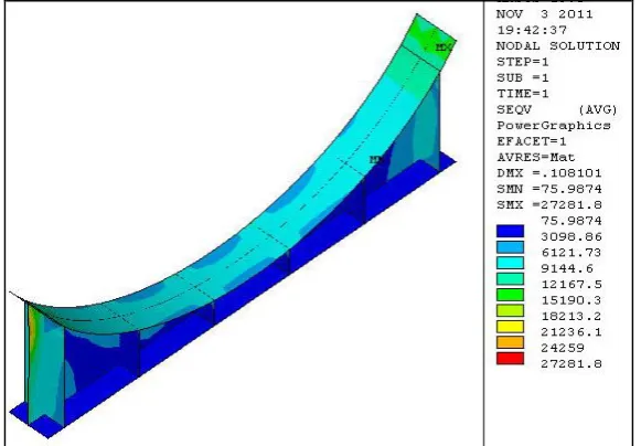
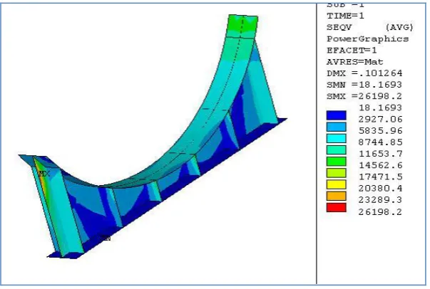
3.3. Case III:- Flat end.
Fig. 10: Equivalent stress in vessel for flat end.
Fig. 11: Equivalent stress in saddle for flat end.
Table 1: Comparative results for stress level in vessel & saddle for hemispherical, semiellipsoidal & flat head end.
Type of end Eqv Stress in vessel (psi) Eqv Stress in saddle (psi)
hemispherical 15432 27281
Semiellipsoidal 16083 32674
flat 15504 26198
By design by analysis approach (DBA) also different head ends effect and their stress level
effect in saddle support and pressure vessel itself is observed and it is concluded that pressure
vessel having flat head ends are having minimum stresses in saddle support and in vessel
4. CONCLUSION
Form the results of finite element analysis software ANSYS we have checked stresses in
saddles for different end-closures such as hemispherical, elliptical and flat end and from the
results in ANSYS the stress value are less in saddle when end closure is flat and the stress
value are maximum in saddle when end –closure is hemispherical.
5. ACKNOWLEDGEMENT
Authors wish to thank Production Engineering Department of D.Y.Patil College of
Engineering, Akurdi, Pune for their support and encouragement.
7. REFERENCES
1. L. P. Zick, “stresses in large horizontal cylindrical pressure vessels on two saddle supports”, the welding journal research supplement, 1951; 959-970.
2. Shafique M.A. Khan, “stress distributions in a horizontal pressure vessels and the saddle supports”, international journal of pressure vessels and piping, 2010; 87: 239-244.
3. Dennis R. Moss, “Pressure Vessel Design Manual-Third Edition”, Gulf Professional
Publication, 2004.
4. K. Magnucki & J. Błachut, “Flexible saddle support of a horizontal cylindrical pressure
vessel,” International Journal of Pressure Vessels and Piping, 2003; 80(3): 205-210.
5. El-Abbasi, “Three-Dimensional Finite Element Analysis of Saddle Supported Pressure Vessels” international journal of mechanical science, 2001; 43: 29-43.
6. American Society of Mechanical Engineering, “boiler and Pressure Vessel code”