An Image Watermarking Approach to Combat
Geometric Attacks using Hybrid DWT, DCT and
SVD Method
Zahra Vahedi
*, Reza Seyfi
Department of Electrical Engineering, Ardabil Branch, Islamic Azad University, Ardabil, Iran [email protected]
Abstract: There are several effective methods for data transmission in ways that no one notices. In this paper, a new scheme based on a combination of DWT, DCT, and SVD domains is presented, in which the main focus is to provide proper solutions for reducing the effect of geometric attacks. To address this goal, we divide the host image into four non-overlapping rectangular segments called sub-images and then the watermark is independently embedded into each of them using the hybrid scheme. In order to correct main geometric attacks, such as rotation, translation, and affine translation, we propose an inventional synchronization technique to recover geometrically attacked image via detection of desired image corners. Simulation results showed that this method can survive attacks like rotation, cropping, JPEG compression, and noising attacks and also can be used for copyright protection of multimedia objects. Experimental simulations are compared with some state of the art robust geometric schemes and the results shows that the proposed scheme has stronger robustness against common signal processing and geometric attacks.
Keywords: Watermarking, DWT, DCT, SVD, Geometric Attacks.
1. Introduction
With the popularity of the internet in recent years, Data sharing including image, video, and audio, have been increased on the website (Moallem et al., 2013; Khalilpour et al., 2013; Mousavi et al., 2013). Therefore manipulating, copy and paste of these data have been simplified for an unauthorized person. Hence, in recent years, protecting of multimedia data has become a popular field of study in the watermarking. Most of the watermarking methods that hide their data in image pixel space use LSB methods.
Since these methods have tried to increase the security of the watermark by using random factors and secret keys, based on the literature on the statistical component of these images, most of these methods are not reliable.
A watermarked image may be revolved due to deliberate or intentional processes. The operation such as compression, geometric attacks that includes: rotating, scaling, transformation, print and scan, filtering, noise and image cropping can be considered as unintentional attacks (Hernández et al., 2014). For example, in the filtering process, if a median filter is applied to the image, all the pixels are arranged in a window and consequently, each pixel will have some moderate value which makes some changes in the watermarking. So that, manipulating image pixel values causes some destruction on the watermarking (Lu and Tan, 2002). In most watermarking applications the method reliability is considered as an important condition so that the hidden information in the host image will be not available to unauthorized persons. In addition to the fact that the utilized watermarking method in these applications should be robust against attacks to remove watermarked information, it must be robust against the unauthorized person with the purpose of detecting and changing the hidden information in the host signal (Chrysochos et al., 2014).
Watermarking is introduced for the first time in 1990 and from that time several types of research have been exponentially introduced (Lei et al., 2012). Over the past years, different watermarking methods have been presented. From a glance, watermarking can be divided into two generations. The first generation is a method where watermarking is performed in the entire media domain. Usually in these methods message inserting performed spatial or transform domains (e.g. DWT and DCT) (Singh et al., 2013). In the spatial domain based watermarking, the transform coefficients vary according to a certain rule (Ramezani et al., 2016). Sometimes, watermarking in the spatial domain has more reliability toward attacks. These methods are robust against attacks such as JPEG compression, noise, filtering and all attacks that do not affect the media geometry. The second generation of the watermarking has been developed as a way to increase the robustness, invisibility and overcoming the problems of the first generation (Kazemi et al., 2017).
37 There are several types of attacks: geometric attack, noise, compression, and image processing attacks (Wenyin and F. Y. Shih, 2011).
Geometric attacks cause synchronization errors during the watermarking extraction process because of that, the quality of watermarked images is affected. Watermarking should be embedded within the same conversion range to prevent synchronization errors.
This paper focuses on the possible attacks against watermarking extraction process which affects the quality of the watermarked images is affected. watermarking should be embedded within the same conversion range to prevent synchronization errors. This paper focuses on possible attacks against watermarking methods on the image, and an effective method is presented for the geometric attacks. In this paper, the details of applying the watermarking methods based on DWT, DCT and SVD have been introduced and the results are analyzed (shahrezaee et al., 2018). In the following, first, we describe the embedding method, the proposed method and the tools used and the parameters for measuring the results (Yu et al., 2006).
Results of the tests are shown in tables and shapes. MATLAB software is used to simulating the presented method. In the end, we compare the experiments results of the introduced method comparing with the previous watermarking methods have been analyzed.
2. Watermark Image Embedding Process
In this part, a combined DWT, DCT and SVD watermarking scheme are proposed in which a gray-scale host image H of size M is used to embed a watermark matrix W.
In order to increase the robustness against the cropping attack, we embed four copies of the watermark into four different segments of the host image. These segments are divided into the up-left, up-right, bottom-left, and bottom-right.
In the watermarking, this kind of decomposition causes to insertion of the watermark into the four different places which reduce the cropping effect. Here, each part of the host image is called sub-image. There are four sub-images including S-H1, S-H2, S-H3, and S-H4 and four identical watermarks from the watermark W including W1, W2, W3, W4. The process of image watermark embedding is as follows:
1) Using haar filter, one-level DWT is applied to the sub-image S-H1 to obtain four sub-bands: LL, LH, HL, and HH. each one is in size .
2) The sub-bands LH and HL are partitioned into non-overlapping blocks and each block is transformed by the DCT operation as given below:
/32 /32 ( , ) 1 1 M N m n m n
LH
LH
(1)/32 /32 ( , ) 1 1 M N m n m n
HL
HL
(2)( , )
(
( , ))
DCT
m n m n
LH
DCT LH
(3)( , )
(
( , ))
DCT
m n m n
HL
DCT HL
(4)3) The first two AC coefficients (Zigzag) of each DCT transformed blocks are selected to put in a matrix A. These two DCT coefficients are located at (1,2) and (2,1) coordination in each block.
4) Each DCT transformed block provides two elements of the matrix A. Therefore, the number of elements in the matrix A is calculated as
. So, its dimension can be .
In this scheme, there is no need to specific rule for the placement regularity of the DCT coefficients from different blocks in the matrix A. However, location of the coefficients used at this stage must be the same as the displacement rule in the other methods as well as the extraction.
/32 /32
( , ) ( , ) ( , ) ( , )
1 1
(
(1, 2),
(2,1),
(1, 2),
(2,1))
M N
DCT DCT DCT DCT m n m n m n m n m n
A
LH
LH
HL
HL
(5)5) The SVD operation is applied to the matrix A and obtained three sub-matrixes are:
U
S
V
SVD A
( )
(6)(6) U is a single matrix and it is called left single value. W1 watermark matrix with Arnold transform is modified to achieve the WScr matrix as follows:
W Scr
S
S
W
(7) where, is the scaling factor. The watermark matrix must be the same size as the S matrix.7) The SVD operation is applied to the modified singular values, as given below:
U
S
W
V
SVD S
(
W)
(8) 8) The modified A-W matrix is calculated as follows:T W
33 In fact, the matrix A-W contains altered AC coefficients.
9) The changed AC coefficients in the block put back to the corresponding position. In other words, the first two AC coefficients from each DCT transformed block that compose the matrix A, are replaced by the corresponding elements of the matrix A-W, achieving watermarked and DCT transformed block which are denoted by and .
10) Inverse DCT operation is applied to blocks to get watermarked sub-bands as follow:
( , )
_
(
( , ))
DCT
m n m n
LH W
Inverse
DCT LH W
(10)( , )
_
(
( , ))
DCT
m n m n
HL W
Inverse
DCT HL W
(11)/32 /32 ( , ) 1 1 M N m n m n
LH
W
LH
W
(12)/32 /32 ( , ) 1 1 M N m n m n
HL W
HL W
(13)
11) Inverse DWT is performed by using two non-modified bands (i.e., LL and HH) and two modified sub-bands (i.e., LH-W and HL-W), obtaining watermarked sub-image SH-W.
The aforementioned steps are similarity repeated for embedding other three copies of the watermark into other three sub-images of the host image H. the resultant will be watermarked image H-W. As a result from the discussion above, using the proposed scheme, a host grayscale image of size can be used to embed a watermark matrix of size .
3. Watermark Extracting Procedure
The watermarked H-W image may be corrupted by the different attack. As discussed, the geometric distortion correction technique is applied to the possibly distorted watermarked image. Then, the restored watermarked image H-W* is partitioned into four sub-images (i.e.,S-H1*,S-H2*,S-H3* and S-H4*), similar to embedding phase. The following steps represent the extraction possibly distorted watermark matrix W1* from a sub-image S-H1* of size .
(1) Using Haar filter, one-level DWT is applied to the sub-image
S
H
1
to obtain four sub-bands: LL*, LH*, HL*, and HH*. Each one will be of size .(2) The sub-bands
LH
and HL* are partitioned into nonoverlapping blocks and each block is transformed by the DCT operation as given below:( , ) /32 /32 1 1 m n M N m n
LH
LH
(14)( , ) /32 /32 1 1 m n M N m n
HL
HL
(15)( , ) ( ( , ))
DCT
m n DCT m n
LH
LH
(16)( , ) ( ( , )).
DCT
m n DCT m n
HL
HL
(17)(3) Only the first two AC coefficients (according to the Zig-Zag order) of each DCT transformed block are selected to put in matrix
A
Similar to step 3 of embedding phase, the two DCT coefficients are located at coordinate (1,2) and (2,1) in each block:/32 /32
( , ) ( , ) ( , ) ( , )
1 1
(
(1, 2),
(2,1),
(1, 2),
(2,1))
M N
DCT DCT DCT DCT m n m n m n m n m n
A
LH
LH
HL
HL
(18)As mentioned, the regular definition of the DCT coefficients from blocks in the matrix
A
must be exactly similar to the placement regularity used in the embedding phase.(4)The SVD operation is applied to matrix A, getting sub-matrices:
(
)
U
S
V
SVD A
(19) (5) the matrixS
W can be achieved as follows:T W
33
.
W scr
S
S
W
(21) (7) Inverse Arnold transform is applied to
W
scrto achieve a possibly distorted watermark matrixW
1
.The aforementioned steps are similarity repeated for extracting other three copies of the watermark (i.e.,
W
2
,3
W
, andW
4
) from the other three sub-images (i.e,S
H
2
,S
H
3
andS
H
4
). The redundancy in different regions of the image can decrease the impact of the cropping attack. In the end, the final extracted watermarkW
can be obtained as :( 1 2 3 4 ) / 4
W W W W W . (22)
If the watermark is a binary matrix, because of the embedding and extracting procedures, the elements of the extracted matrix may be turned to the fractional numbers between zero and one. So, in this case, each element of the final output must be amended by the following rule:
0 ( , ) 0.5
( , )
1 ( , ) 0.5
Binary
W i j
W i j
W i j
(23)
So that,(i, j) denotes the position of an element in the watermark matrix which can be a grayscale or binary image.
4. The Proposed Method For Geometric Attacks Correction
Fig.1.illustrates the Lena image with its attacked versions including (a) un-attacked, (b) 25° rotation (c) 70° rotation, (d) [100,80] translation, and (e) affine transformation [0.9,0.2,0-0.1,1.2,0,0,0] attacked images using MATLAB 2017b software.
As it is seen, after such destructions a margin is created around the main image, so that the margin is composed of pixels with the same intensity values. This feature is the main motive of the proposed method. In fact, we try to identify boundary and corners of the main region with the help of the margin. In this paper, the term “main region” refers to the region that represents the desired image. In other words, the main region does not contain the generated margin. Also, the 0term “entire image” refers to the entire region containing both the desired image and the margin.
Fig.1.Lena image and attacked versions: (a) un-attacked, (b) rotation 25° (c) rotation70°(d) translation (100,80) and (e) affine transformation[0.9,0.2,0;0.1,1.2,0;0,0,0]
The margin leads to the emerging edge where the edge can be a boundary of the main region. However, the boundary is not identifiable; the pixel values of the margin and the main region are similar. Nevertheless, the overall procedure does not fail; the proposed image reconstruction technique is performed based on the corners of the main region, such that other boundary pixels are not necessary. The detailed steps of the proposed technique for geometric distortion correction can be described as follows:
(1) A deliberate margin is attached to the entire image. As mentioned, a margin is necessary to distinguish the boundary. But, the margin is not generated in some cases like the un-attacked image. On the other hand, the correction technique is applied to the image without any knowledge about the probable attacks. So, the step should be performed to guarantee the required margin around the main region. Based on our experiments, an additional margin of length five pixels is sufficient for our purpose.
(2) The Canny edge detector [23] is applied to the entire image. Fig.2 shows different kinds of edges resulted from the rotated version of the Lena image. The boundary of the main region clearly appears.
04 (3)The additional margin attached in step 1 is removed.
(4) Morphological closing operation with a square structuring element is applied. This operation joins narrow break edges, resulting in a clearer boundary.
(5) Four corners of the main region are recognized based on minimum distance to the corners of the entire image. To do this, the entire image is divided into four square segments: up-left segment, up-right segment, bottom-left segment, and bottom-right segment.
In each segment, one corner must be recognized. The corner of each segment is a point on the boundary that has a minimum distance to the entire image corner located in the same segment. For example, in the up-left segment, to recognize the corner of the main region, the distances of the boundary points are calculated from the up-left corner of the entire image.
In the next step, the corrected image using the probably attacked image. The corners are labeled from 1 to 4, as can be seen in Fig.3.
Fig.3.An image to show the corner labels and moving directions.
(6) The pixels, being inside the region determined by the four corners, are used to reconstruct the unattacked image. As mentioned, the main region is restricted to the four corners illustrated by Fig.4.
Fig.4. Four different segments of the image.
Suppose that there is a line between corner one and corner two. The pixels located on this line are put in the first row of a new matrix. The matrix will be the reconstructed image and its dimensions are determined based on the four corners.
Then, we must move from corner one to corner three for the first point, and also from corner two to corner four for the last point of the next line. VIA the next lines, values of the next rows of the new matrix are achieved. For this, in each line, we must move from the first point to the last point of the line to access the middle points (See Fig.4).
Also, when moving from corner one to three and moving corner two to four, we need to access middle points as the first points and the last points. Thus, the problem is only to find the coordinates of the first point and the last point of that line. Note that, the images which we deal with is digital. It means that a number of middle points and their coordinates are an integer. The number of discrete points (including the first and the last points) can be calculated as follows:
Bottom-right
Bottom-left
Up-left
Up-right
1
2
3
04
2 2
1 1 2 2
(
)
(
)
1
L
e
h
e
h
(24)where,
( ,
h h
1 2)
denotes the coordinate of the first point and( ,
e e
1 2)
describes the coordinate of the last point of the line. In fact, L-1 can be the length of the line in terms of the pixel. Likewise, to calculate the coordinate of the points located on the line, we use the following equation:1 1 1 1
(
1)(
)
(
)
1
i
i
e
h
P
h
round
L
(25)2 2 2 2
(
1)(
)
(
)
1
i
i
e
h
P
h
round
L
(26)Here, operation round (.) denotes the nearest integer number,
i
1, 2,..., ;
L
in which the coordinate of thei
th point is indicated by(
P
1i,
P
2i)
.The images destroyed by the rotation, translation, and affine transformation, can be easily recovered by the proposed technique. However, a watermarking scheme is required to be robust against other attacks, as well.
5. Simulation
To illustrate the effectiveness of the proposed scheme, some recent works on geometric robustness are chosen for comparison. we compared the results in terms of stability and invisibility.
In the proposed watermarking scheme we chose Lena, pepper, Barbara gray-scale test images with a size of
as the host images and the cameraman image with a size of 128×128 as the watermark image that shown in fig.5.
Some distortions are applied to the watermarked image. There are several methods to review the quality of the watermarked images after the watermarking process and applying distortions. PSNR (Peak Signal to Noise Ratio) and MSE (Mean Squared Error) are two common measurement method where the visual quality of (×S) watermarking image extraction and main watermarking (S) image is examined.
PSNR is defined as follow (L is the vector length of x).
2
2
1
( ( ) )
( ,
) 10 log
( ( )
( ))
L i
Maximum x i
PSNR S S
L
x i
x
i
(27) MSE is calculated as follow :2 1
1
(
)
n i i iMSE
x
x
n
(28)(a)
(b)
(c)
Fig.5. (a) Used host images Barbara, Peppers, and Lena (b) Cameraman watermark image in size
128 128
(c) Watermarked image6. Test of Invisibility
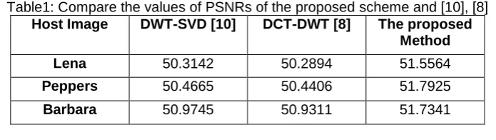
04 Table1: Compare the values of PSNRs of the proposed scheme and [10], [8]
Host Image DWT-SVD [10] DCT-DWT [8] The proposed Method
Lena 50.3142 50.2894 51.5564
Peppers 50.4665 50.4406 51.7925
Barbara 50.9745 50.9311 51.7341
Table2: Compare the values of MSE from the implementation of the proposed scheme Host Image DWT-SVD DCT-DWT The proposed Method
Lena 45.1037 45.6418 46.4122
Peppers 45.1469 45.2279 46.3126 Barbara 45.3989 45.6511 46.9455
6.1. JPEG compression
Robustness is testified against different types of attack. Attacks are applied to the watermarked image and the hidden image obtained from the watermarking image by using the watermark extraction algorithm.
The Pearson correlation coefficient has been used for the comparison of the correlations between the main watermarked image with the extracted watermarked image. This scheme can be robust against the JPEG compression with a quality factor up to 30 that is illustrated in Table 3. Fig.8 shows the simulation results after JPEG compression.
Table 3. The comparison of the values of the Pearson correlation coefficients extracted from JPEG compression.
Compression coefficient
DWT-SVD [10] DCT-DWT [8] The proposed Method
10 0.9537 0.9318 0.9844
20 0.9143 0.8799 0.9515
30 0.8558 0.8487 0.9192
Fig.6. The extracted watermarked images from the JPEG compression
6.2. Gaussian noise attack
In this part, Gaussian noise is added to the watermarked image. Fig.7 shows the generated watermarks that appear after Gaussian attack. Table 4 illustrates the comparison of the proposed method with the DWT-DCT against the Gaussian attack.
Table 4. The comparison of the values of the Pearson correlation coefficient of the watermarking images resulting from Gaussian noise attack
Mean value DWT-SVD DCT-DWT The proposed Method
0.8 0.9998 0.9998 0.9998
1.2 0.9964 0.9957 0.9994
03 Fig.7. The extractor watermarked images from the Gaussian noise attack
6.3. Signal Processing Attack
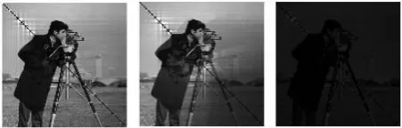
Watermarking images can also be identified after applying ordinary signal processing. Fig.8 shows the simulation results for the medium filtering or blurring.
Fig.8. The extracted watermarked images after applying the signal processing attack
Table 5 shows the value of Pearson’s correlation coefficient from the watermark image in the signal processing. Table 5. The comparison of the Pearson correlation values of the watermarked images obtained from the signal
processing.
Host Image DWT-SVD DCT-DWT The proposed Method
0.8 0.9249 0.9355 0.9998
1.2 0.8856 0.9078 0.9994
1.6 0.8149 0.8442 0.9992
6.4. Cropping Attacks
From the simulation results of Table 6, it can be seen that the proposed scheme is robust against the cropping attacks. As shown in Fig.8, watermarked images are also visible after the cropping attack.
Table 6 illustrates the values of the Pearson correlation coefficient of the watermark image against the cropping attack.
Table 6. The comparison of the Pearson correlation coefficients from the watermark image against the cropping attack
Crop DWT-SVD DCT-DWT The proposed Method
1/4 columns from the left 0.8740 0.8677 0.9920 1/4 rows from the right 0.8564 0.8450 0.9886 1/4 columns from the left 0.8466 0.8188 0.9156
00
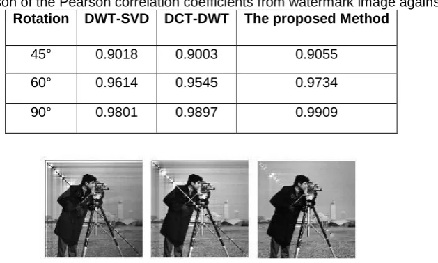
6.5. Rotation attack
The simulation results in Table 7 illustrates that the proposed method is more robust against rotation attack. Figure 10 shows the simulation results for different angles.
Table 7. The comparison of the Pearson correlation coefficients from watermark image against rotation attack. Rotation DWT-SVD DCT-DWT The proposed Method
45° 0.9018 0.9003 0.9055
60° 0.9614 0.9545 0.9734
90° 0.9801 0.9897 0.9909
Fig.10. watermark images extracted after rotation attack 7. Conclusion
Considering the past works in this field we intended to develop a watermarking algorithms using discrete cosine transform and discrete wavelet transforms. For this purpose,we used a combination of the watermarking methods including Discrete Cosine Transform, Discrete Wavelet Transform and Singular Value Decomposition. The simulation results showed that this method destroys attacks, such as rotation, cropping, JPEG compression and noise destruction and can also be used to protect copyright of the multimedia objects. Given that the method of the watermarking has been used in the frequency domain, there is no apparent difference between the initial image and the final image. Therefore, this is largely dependent on the watermarking capacity. Since there is practically no limitation to the way data is hid in the image, it can be used desirable relative capacity that appearance of the image also does not change. Therefore, the proposed method can be considered safe. In this paper, a new method is proposed for image retrieval of the attacked images by considering the image edges. It was also shown that the watermark image is more robust against the cropping attack. To compare the results with the previous references, the values of the parameters such as Peak Signal to Noise Ratio (PSNR), Mean Squared Error (MSE) and Pearson correlation coefficient have been used. Various tests have been analyzed for attacks and the results showed that the extracted watermark is similar to the main watermark. The proposed method was tested for stability testing, such as JPEG compression, noise attack, signal processing and so on. After the image was subjected to various attacks, the extracted watermark is still visible. also comparing the values of PSNR and MSE from the implementation of the proposed methods, and the use of the previous methods, you see that these values are better than the previous methods. The simulation results compared with two state of the art methods to show the system superiority.
References
A. Mishra, C. Agarwal, A. Sharma and P. Bedi, (2014). Optimized grayscale image watermarking using DWT–SVD and firefly algorithm, Expert Systems with Applications, 41(17), 7858-7867.
B. Lei, I.Y. Soon, F. Zhou, Z. Li and H. Lei, (2012). A robust audio watermarking scheme based on lifting wavelet transform and singular value decomposition, Signal Processing science direct, 92(9), 1985-2001.
C. Singh, S. Ukhjeet and K. Ranade, (2013). Geometrically invariant and high capacity image watermarking scheme using accurate radial transform, Optics & Laser Technology science direct, 54, 176-184.
D. Yu, F. Sattar and B. Barkat, (2006). Multiresolution fragile watermarking using complex chirp signals for content authentication, Pattern Recognition, 39(5), 935-952, 2006.
E. Chrysochos, V. Fotopoulos, M. Xenos and A. N. Skodras, (2014). Hybrid watermarking based on chaos and histogram modification, Signal, Image and Video Processing, 8(5), 843–857.
Khalilpour, M., Razmjooy, N. (2013). A Hybrid Method for Gesture Recognition. J. of World’s Elect. Eng. Techno, 4(2), 70-75.
Manuel C. Hernández, Francisco G. Ugalde, Mariko N. Miyatake and Héctor Manuel P. Meana, (2014). Robust hybrid color image watermarking method based on DFT domain and 2D histogram modification, Signal, Image and Video Processing, 8(1), 49–63.
04
Mousavi, B. S., Soleymani, F., Razmjooy, N., (2013). Color image segmentation using neuro-fuzzy system in a novel optimized color space, Neural Computing and Applications, 23(5), 1513-1520.
M. F. Kazemi, M. A. Pourmina and A. H. Mazinan, (2017). A new image watermarking framework based on levels-directions decomposition in contourlet representation, Journal of Central South University, 24(3), 521–532.
R. Lu and T. Tan, (2002). An SVD-based watermarking scheme for protecting rightful ownership, IEEE Transactions on Multimedia, 4(1), Mar 2002.
Shahrezaee, M., and Navid Razmjooy, (2018). Image Watermarking Based on DWT-SVD.
V. Aslantas, S. Ozer and S. Ozturk, (2009). Improving the performance of DCT-based fragile watermarking using intelligent optimization algorithms, Optics Communications, 282(14), 2806-2817.
Razmjooy, N., Ramezani, M., (2016). Training wavelet neural networks using hybrid particle swarm optimization and gravitational search algorithm for system identification, Int. J. Mechatron. Electron. Comput. Technol, 6(21), 2987-2997. Z. Wenyin and F. Y. Shih, (2011). Semi-fragile spatial watermarking based on local binary pattern operators, Optics