WWJMRD 2018; 4(2): 345-354 www.wwjmrd.com
International Journal Peer Reviewed Journal Refereed Journal Indexed Journal UGC Approved Journal Impact Factor MJIF: 4.25 E-ISSN: 2454-6615
R.Maheswar Reddy
Deaprtment of EEE, Sree Vidyanikethan Engineering College, Tirupati, Andhra Pradesh, India
B.Subba Reddy
Deaprtment of EEE, Sree Vidyanikethan Engineering College, Tirupati, Andhra Pradesh, India
Correspondence:
R.Maheswar Reddy
Deaprtment of EEE, Sree Vidyanikethan Engineering College, Tirupati, Andhra Pradesh, India
Adaptive Filter Implementation Based Control
Algorithm for Distribution Static Compensator
R.Maheswar Reddy,
B.Subba Reddy
Abstract
This paper presents the adaptive filter implementation based on a control algorithm for a distribution static compensator (DSTATCOM) which is used for both linear and nonlinear loads in three phase distorted voltage ac mains. By using proposed filter the fundamental active and reactive components of load currents are extracted for estimation of reference supply currents. This control algorithm is implemented on a developed DSTATCOM for harmonic elimination, reactive-power compensation and load balancing under linear and non-linear loads.
Keywords: Adaptive Filter (AF), Distribution Static Compensator (DSTATCOM), harmonic
elimination, load balancing.
1. Introduction
Except in a very few special situations, electrical energy is produced, transmitted, distributed, and utilized as alternating current (AC). However, alternating current has various definite disadvantages. One of these is the necessity of reactive power that requires to be supplied along with active power. Reactive power can be leading or lagging. While it is the active power that tends to the energy consumed, or transmitted, reactive power does not contribute to the energy. Reactive power is an immanent part of the „„total power.‟‟ Any electrical power system consists of wide range of electrical, electronics and power electronics equipment in commercial and industrial administration. Modern power systems are complex networks, where thousands of load centers and hundreds of generating stations are interconnected through long power transmission and distribution networks [1].Even though the generated power in most countries is fairly definitive, the quality of power is not so reliable. Power distribution system should dispense their customers with continuous supply of energy at smooth sinusoidal voltage at the undertaken magnitude level and frequency. Power system especially distribution systems have numerous non-linear loads, which notably affect the quality of power supplies [2]. This ends up producing many power quality problems like, sag, swell, poor power factor, harmonics, unbalancing of load, etc. In proposed project these power quality problems can be mitigated by using Distribution Static Compensator (DSTATCOM) and Adaptive Filter (AF). The objective is to implement an adaptive filter in a three phase DSTATCOM used for compensation of linear/nonlinear loads in a three-phase distorted voltage ac mains. The proposed control algorithm will be implemented on a developed DSTATCOM for reactive power compensation, Harmonics elimination, load balancing and voltage regulation under linear and nonlinear loads.
2. Proposed Dstatcom Topology
The basic function of DSTATCOMs is to mitigate most of the current based power quality problems such as reactive power, unbalanced currents, neutral current, and harmonics (if any) and to provide sinusoidal balanced currents in the supply with the self supporting DC bus of the voltage source converter (VSC) used as a DSTATCOM[3]. Using a control algorithm, the reference DSTATCOM currents are directly controlled by estimating the reference DSTATCOM currents. However, in place of DSTATCOM currents, the reference supply currents may be estimated for an indirect current control of the VSC. The gating
pulses to the DSTATCOM are generated by employing hysteresis or pulse width modulation (PWM) current control over reference and sensed supply currents resulting in an indirect current control. Using the DSTATCOM, the reactive power compensation and unbalanced current compensation are achieved in all the control algorithms. In addition zero voltage regulation (ZVR) at point of common coupling (PCC) is also achieved by modifying the control algorithm suitably [4].
2.1 Principle of operation of DSTATCOMs
The main objective of DSTATCOM is to mitigate the current-based power quality problem in a distribution system. In general, a DSTATCOM has a VSC connected to a DC bus and its AC sides are connected in shunt normally across the consumer loads or across the PCC. It requires Hall Effect voltage and current sensors for feedback signals
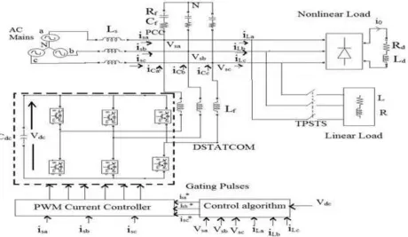
and normally a digital signal processing (DSP) is used to implement the required control algorithm to generate gating signals for the solid-state devices of the VSC of the DSTATCOM. The VSC is normally controlled in PWM current control mode to inject appropriate currents in the system [5]. The DSTATCOM also needs many passive elements such as a DC bus capacitor, AC interacting inductors, injection and isolation transformers, and small passive filtersFig.1 shows a schematic of a DSTATCOM connected to three-phase ac mains feeding three-phase linear/non-linear loads. Three-phase linear and non-linear loads are connected through three-pole single-throw switch (TPSTS) at the PCC, as shown in the Fig.1. The TPSTS is used for disconnection of linear loads, and for single operation, another single-pole single-throw switch is used, which is not shown in the Fig.1 [6]
Fig.1: Schematic of three-leg DSTATCOM.
A three phase diode bridge rectifier with resistive load (Rd) and filter inductance (Ld) is modeled as a nonlinear load for testing purposes. This type of load has zero demand of reactive power in an ideal condition. A set of three-phase resistors (R) with inductors (L) is modeled as a linear load. Ls and Rs are considered as ac mains independence parameters (Zs)[1]. The normal available grid voltage with an extra supply inductance is considered as the distorted voltage ac mains.
2.2 Control of DSTATCOM
The main objective of a control algorithm of DSTATCOMs is to estimate the reference currents using feedback signals. These reference currents along with corresponding sensed currents are used in PWM current controllers to derive PWM gating signals for switching devices of the VSC used as a DSTATCOM. Reference currents for the control of DSTATCOMs have to be derived accordingly and these
signals may be estimated using a number of control algorithms. There are many control algorithms reported in the literature for the control of DSTATCOMs, which are classified as time-domain and frequency-domain control algorithms. All these control algorithms may be used for control of DSTATCOMs [7].
3 Mathematical Modelling
Fig. 2 shows a block diagram of the proposed AF based on the adaptive nature for synchronous extraction in the time domain for deriving reference supply currents. It is applied under distorted ac mains feeding to linear and nonlinear loads. The basic steps for estimation of different control variables of the control algorithm are given below.
The sinusoidal-tracking algorithm is used for extraction of phase “a” sinθva and cosθva component of distorted PCC voltages as unit templates in adaptive nature.
The amplitude of the three-phase voltage is given as,
{ ⁄ ( )} ⁄
(1)
where Vsa, Vsb, and Vsc are PCC phase voltages.
The in-phase component of PCC phase “a” voltage is written as
(2)
The quadrature component of PCC phase “a” voltage is
(3)
The in-phase and quadrature components of phases “b” and “c” of PCC voltages Vpb, Vpc and Vqb, Vqc are
estimated in a similar manner.
3.1.1 Estimation of Amplitude of Active- and Reactive-Power Components of Load Current
Active-power, reactive-power, and harmonics components of load currents are the principal components in distorted and lagging power factor load currents. Active- and reactive-power components of phase “a” load current are subtracted from the original load current, and the produced error is multiplied with the PCC voltage in-phase component (Vpa). This signal is passed through a low pass filter (LPF) prior to integration. After integration with a proper constant, this component is again multiplied with the in-phase component of PCC voltage (Vpa) in a closed loop system. The active-power component of phase “a” load current (iLpa1) is extracted from the original load current using the foregoing procedure in adaptive nature. After extraction of the active-power component of load current, its root-mean-square value is evaluated and converted to a peak value using gain (G). The amplitude of the estimated active power component of phase “a” load current is iLpa. Similarly, the amplitude of the active component of phase “b” and phase “c” load currents iLpb
and iLpc are estimated.For withdrawal of the reactive-power component of load current, an error signal is multiplied with the quadrature component of PCC voltage (Vqa). After integration of this component again multiply with Vqa term to extract the reactive-power component of phase “a” load current (iLqa1). After extraction of the reactive-power component of load current, its root-mean square value is evaluated and converted to a peak value using gain (G). The amplitude of the reactive-power component of phase “a” load current is “iLqa.” Similarly, the amplitude of the reactive-power component of phase “b” and phase “c” load currents iLqb and iLqc are evaluated. The amplitudes of average fundamental active- and reactive-power components of load currents of three-phase loads are estimated using the amplitude sum of individual three-phase active- and reactive-power components of loads divided by 3. In terms of mathematical expressions, these are expressed as
( ) ⁄ (4)
( ) ⁄ (5)
3.1.2 Amplitude of Active- and Reactive-power Components of Reference Supply Currents
The load currents, PCC voltages and dc bus voltage are sensed as a feedback signal. The load currents from the a-b-c frame are first a-b-converted to α-β-0 frame and then to d-q-0 frame[8].The input to the first PI controller is the error between the reference dc bus voltage V*dc and the sensed dc bus voltage (Vdc) of DSTATCOM. Reference and sensed dc-link voltage of VSC of DSTATCOM are used to calculate voltage error, which is given to a proportional- integral (PI) controller, and its output is required for maintaining the dc-link voltage of the DSTATCOM. The output of the dc-link PI controller is considered asIloss.
( ) ( ( ) ( ))
( ) (6)
where, Kpd and Kid are the proportional and integral gains of the dc bus voltage PI controller.
The amplitude of the active-power component of the reference supply current (Ispt) is calculated by an addition of the output of the dc-link PI controller (Iloss) and the average magnitude of load active currents (ILpA) as
(7)
The actual and reference PCC voltage are delivered to another PI controller for regulating the PCC voltage. The reference quadrature current iqr is the output of the PI controller. This iqr is added to the dc component of iq [8].
( ) ( ( ) ( )) ( )
where, Kpq and Kiq are the proportional and integral gains of the PCC voltage PI controller.
The generated reference quadrature axis current is
(9)
3.1.3 Estimation of Reference Supply Currents and Generation of Gating Pulses
Three-phase reference supply currents are calculated using an amplitude of three-phase (a, b, and c) load active-power components of currents, reactive-power components of currents, and sinθ and cosθ components of PCC voltages. Three phase reference supply active- and reactive-power components of currents are evaluated as
,
(10)
.
, (11)
.
Total three-phase reference supply currents are evaluated by the addition of reference active- and reactive-power components of currents as
(12)
The sensed supply currents (isa, isb, isc) and these reference supply currents (i*sa, i*sb, i*sc) are compared for their respective phases, and each phase current error is amplified using PI controllers, and outputs of PI current controllers are fed to a pulse width modulation controller to generate the gating signals for IGBTs of VSC used as DSTATCOM [10]
3.1.4 Control Strategy
The control strategy is primarily implemented to control a DSTATCOM that is control the amount of reactive power exchange between the DSTATCOM and the supply bus. The reference compensation currents for the DSTATCOM are thereby concluded as the difference between the actual load current and the desired source current in each phase.
(13)
When the PCC voltage is less than the reference value then the DSTATCOM generates reactive power and when PCC voltage is more than the reference value then the DSTATCOM absorbs reactive power. To attain the desired characteristics the firing pulses to PWM are controlled. The output of PI controllers is the difference of reference supply currents and sensed supply currents. The generator finally generates triggering pulses such that the voltage imbalance is corrected [10]
Fig.3: Block diagram of control strategy
4. Results and Discussions.
The overall design process can be shortened through the use of computer simulations, since it is usually easier to study the influence of a parameter on the system behavior in simulation. A VSC-based DSTATCOM is developed in the simulation using IGBTs. An AF-based control algorithm of the DSTATCOM system is implemented using MATLAB and Sim Power System toolboxes. The proposed control algorithm is modified using a band-pass filter on PCC voltages and an LPF on the estimated amplitude of PCC voltages. During these tests, the dc-link voltage of DSTATCOM is regulated to a reference value of 200 V, and test results are recorded in PFC mode of operation of DSTATCOM. The main purpose of simulation is to study different aspects like to check the performance of AF, Steady-State Performance of DSTATCOM at Linear and Nonlinear Loads in PFC Mode, Dynamic Performance of DSTATCOM in PFC Mode.
(b)
(c)
Fig. 4: (a), (b) and (c) Various intermediate signals of the control algorithm at load injection
A. Performance of AF
Fig. 4(a)–(c) shows the various intermediate signals of the control algorithm, which include phase “a” distorted-voltage waveform(Vsa), filtered-voltage waveform(Vsa1), load current (iLa), average amplitude value of load active (ILpA)and reactive current(ILqA), output of dc-link PI controller (Iloss), amplitude of total active-current component(Ispt), active component of the reference supply current(isap), output of ac-bus PI controller(Iqr), amplitude of total reactive-current component of the reference supply current(Isqt), reactive component of the reference supply current(isaq), and reference supply current(i sa), respectively. Extraction of these control signals under load injection is shown in Fig. 4(a)–(c), respectively, which demonstrate the variation and extraction speed of control signals using the proposed AF under time-varying nonlinear load in ZVR mode of DSTATCOM. Fast action of AF can be seen at a time of load injection in the estimation of the reference supply current with other signals. The reference supply current is synchronously varying with extracted other signals. In this application, this filter is used in an indirect current approach for controlling power-quality problems.
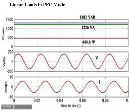
B. Steady-State Performance of DSTATCOM at Linear Loads in PFC Mode
(b)
Fig. 5: (a) and (b) PS and PL of linear lagging pf load without DSTATCOM
(a)
(b)
(c)
Fig. 6: Steady-state performance of DSTATCOM at linear lagging PF load in PFC mode. (a)Ps, (b)PL, (c)Pc.
The supply side and load side power factors of a phase 3-wire system have measured without using DSTATCOM. The supply power factor of a linear load without DSTATCOM is 0.36 and load side power factor is 0.3. Fig. 5. (a) and (b) shows the PS and PL values of a system with linear lagging pf(Power Factor) load without DSTATCOM. The values of supply and load apparent powers are 1226 VA and 1343VA. Supply power(Ps), load power (PL), and compensator power(Pc) are shown in Fig. 6(a)–(c) for a 0.92-pf (DPF) lagging three-phase linear loads. The values of supply and load apparent power are 948.9 VA and 964.1 VA, respectively. The power factor on the supply side is improved to near unity (0.99 DPF) as the reactive-power demand of the load is compensated by the DSTATCOM with the proposed AF. It is observed that PCC voltage drops from rated value due to supply impedance and load demand, but the power factor is maintained to unity.
C. Dynamic Performance of DSTATCOM at Unbalanced Linear Load in PFC Mode
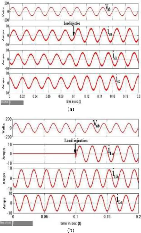
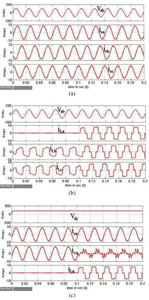
Fig. 7. (a) and (b) shows the waveforms of supply currents (isa, isb, isc) and load currents (iLa, iLb, iLc) with distorted PCC line voltage (vab) under unbalanced linear loads. An unbalanced load condition is created by the removal of load in phase “a.” The variation of supply current (isa), DSTATCOM current (iCa), and load current (iLa) are shown with dc-link voltage (vdc) in Fig. 7. (c). It is observed that during load unbalancing, dc-link voltage regulated at the reference level without any variation.
(a)
(c)
Fig. 7: Dynamic performance of DSTATCOM at unbalanced linear loads. (a) vab, isa, isb, isc. (b) vab, iLa, iLb, iLc. (c) vdc, isa, iCa,
iLa.
It shows the function of DSTATCOM for load balancing and also observed the fast action of AF during sudden load injection. Load injection in phase “a” (iLa) and action of DSTATCOM current (iCa) is observed at the same time. Table I shows the values of three-phase supply currents (isa, isb, isc), load currents (iLa, iLb, iLc), with and without DSTATCOM under unbalanced linear loads. Under unbalanced load with DSTATCOM, three supply currents and load currents are 5.8 A, 5.8 A, 5.8 A and 0 A, 8.5 A, 8.5 A, respectively. It shows almost balanced supply currents when load currents are unbalanced. These results show satisfactory performance of the AF used in DSTATCOM for load balancing under linear loads.
Table 1 Supply and load currents at unbalanced load without and with DSTATCOM
Performance Parameters Without DSTATCOM With DSTATCOM
Phase-a Phase-b Phase -c Phase-a Phase-b Phase-c
Supply urrents(A) 9.7 5.73 5.73 7 7 7
Load urrents(A) 17.57 10.5 10.5 8.4 8.4 8
D Steady-State Performance of DSTATCOM at Nonlinear Load in PFC Mode
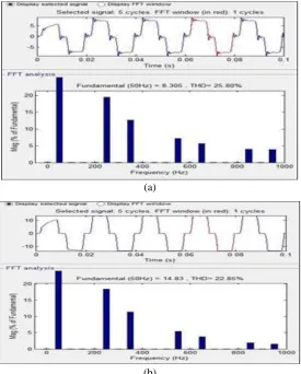
The supply side and load side THDs of a 3-phase 3-wire system have measured without using DSTATCOM. The THD of source current of a non-linear load without
DSTATCOM is 25.80% and THD of load current is 22.85%. Fig. 8. (a) and (b) shows the THD values of the system with non-linear load without DSTATCOM. linear load without DSTATCOM.
(a)
(b)
(a)
(b)
(c)
(d)
(e)
(f)
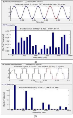
Fig. 9: Steady-state performance of DSTATCOM at nonlinear loads in PFC mode. (a) vab, isa. (b) vbc, isb. (c) vca, isc. (d) vab, iLa.
(e) Harmonic spectrum of isa. (f) Harmonic spectrum of iLa
Fig. 9(a)–(f) shows the waveform of three-phase PCC voltages (vab, vbc, vca) with respective phase supply currents (isa, isb, isc), harmonic spectrum of phase “a” supply current and distorted waveform of phase “a” load current (iLa) and its harmonic spectrum under three diode-based rectifier loads. In Fig. 6(d) and (f), total harmonic distortions (THDs) of the phase “a” supply current and load current are 2.84% and 25.34%, respectively. These results show satisfactory performance of the proposed control algorithm used in DSTATCOM for reactive power compensation and harmonics suppression under linear and nonlinear loads, respectively.
E. Dynamic Performance of DSTATCOM at Unbalanced Non-linear Load in PFC Mode
(a)
(b)
(c)
Fig. 10: Dynamic performance of DSTATCOM at unbalanced non-linear loads. (a) vab, isa, isb, isc. (b) vab, iLa, iLb, iLc. (c) vdc, isa,
iCa, iLa
An unbalanced load condition is created by the removal of load in phase “a.” The variation of supply current (isa), DSTATCOM current (iCa), and load current (iLa) are shown with dc-link voltage (vdc) in Fig. 10. (c). It is observed that during load unbalancing, dc-link voltage regulated at the reference level without any variation. It shows the function of DSTATCOM for load balancing and also observed the fast action of AF during sudden load injection. Load injection in phase “a” (iLa)
Conclusion
A DSTATCOM has been implemented for a three-phase distribution system. An AF has been used for control of DSTATCOM. This AF has been found simple and easy to implement, and its performance has been observed satisfactory with non-sinusoidal and distorted voltages of ac mains under load variation. The performance of
DSTATCOM with its AF has been demonstrated for harmonics elimination, reactive power compensation, and load balancing with self-supporting dc link in PFC mode. The dc-link voltage of the DSTATCOM has been also regulated to a desired value under time-varying load conditions.
Appendix A
A simulation block of DSTATCOM is developed in the MATLAB simulink. Components of DSTATCOM include VSC with self-supporting dc link, interfacing inductors, and ripple filters. The design guideline of various components of VSC, interfacing inductors, and ripple filters is given below [5].AC supply: three-phase, 110 V (L-L), 50 Hz; Extra added supply inductance: Ls = 2 mH with small internal resistance; Load: (1) Linear: Parallel-connected resistive load bank 110 V, 25 Ω, 110 V, 20 Ω, and inductor 70 mH;Nonlinear:Three phase full-bridge uncontrolled rectifier, with R = 19 Ω and L = 100 mH; DC-link capacitance: 1650 μF; Ripple filter: Rf = 5 Ω, Cf = 10 μF; DC-link voltage: 200 V; Interfacing inductance (Lf ): 2.5 mH; Gains of PI controller for dc-link voltage: kpp = 0.35, kip = 0.04; Gains of PI controller for ac bus voltage: kpq = 3, kiq = 1.1; Value of integral constant in active-power components = 0.0015; Value of integral constant in reactive-power components = 0.0003; Cut-off frequency of band pass filter used in ac mains: first order, 30–70 Hz; Cut-off frequency of low filter used in amplitude of terminal voltage: second order, 12 Hz; Cut-off frequency of low filter used in dc-link voltage: first order, 15 Hz; Sampling frequency (fs) = 12 kHz.
References
1. J. Jacobs, D. Detjen, C. U. Karipidis, And R. W. De Doncker. Rapid prototyping tools for power electronic systems: Demonstration with shunt active power filters. IEEE Transactions on Power Electronics. 2004, vol. 19, iss. 2, no. 2, pp. 500–507. ISSN 0885-8993. DOI: 10.1109/TPEL.2003.823240.
2. K. R. Padiyar. FACTS Controllers in Power Transmission and Distribution. New Delhi. 2008. India: New Age International.
3. S. B. Karanki, N. Geddada, M. K. Mishra, And B. K. Kumar. A DSTATCOM topology with reduced DC-link voltage rating for load compensation with non-stiff source. IEEE Transactions on Power Electronics. 2012, vol. 27, iss. 3, pp. 1201–1211. ISSN 0885-8993. DOI: 10.1109/TPEL.2011.2163946.
4. Singh, P. Jayaprakash, and D. P. Kothari. A T-connected transformer and three-leg VSC based DSTATCOM for power quality improvement. IEEE Transactions on Power Electronics. 2008, vol. 23, iss. 6, pp. 2710–2718. ISSN 0885-8993. DOI: 10.1109/TPEL.2008.2004273.
5. R. R. Sawant and M. C. Chandorkar. A multifunctional four-leg grid connected compensator. IEEE Transactions on Industrial Applications. 2009, vol. 45, iss.1, pp.249– 259. ISSN 0093-9994. DOI: 10.1109/TIA.2008.2009704.
Signal Processing. 2004, vol. 52, iss. 6, pp. 1585– 1595. ISSN 1053-587X. DOI: 10.1109/TSP.2004.827155.
7. Chandra, B. Singh, B. N. Singh, and K. Al-Haddad. An improved control algorithm of shunt active filter for voltage regulation, harmonic elimination, power-factor correction, and balancing of nonlinear loads. IEEE Transactions on Power Electronics. 2000, vol. 15, iss. 3, pp. 495–507. ISSN 0885-8993. DOI: 10.1109/63.844510.
8. N. Singh, A. Adya, A. P. Mittal and Bhim Singh. Application of DSTATCOM for Mitigation of Voltage Sag for Motor Loads in Isolated Distribution Systems. IEEE International Symposium on Industrial Electronics. 2006, vol. 3, pp. 1806-1811. ISSN 2163-5137. DOI: 10.1109/ISIE.2006.295846.
9. Hirofumi Akagi and Hideaki Fujita. A New Power Line Conditioner for Harmonic Compensation in Power Systems. IEEE Transactions on Power Delivery. 1995, Vol. 10. iss. 3 pp. 1570 - 1575. ISSN 0885-8977. DOI: 10.1109/61.400941.