DTLS based Security and Two-Way Authentication for the Internet of Things
Full text
Figure
![Figure 1: A DTLS record protected with CBC block cipher [1]. ClientHello* ClientHelloVerify*ClientHelloFinished ChangeCipherSpecFinishedFlight 1Flight 3Flight 5 Flight 2Flight 4Flight 6ServerHello, Ceritifcate,](https://thumb-us.123doks.com/thumbv2/123dok_us/9782381.2469970/7.918.349.712.175.346/figure-protected-clienthello-clienthelloverify-clienthellofinished-changecipherspecfinishedflight-serverhello-ceritifcate.webp)
![Figure 3: Protocol stack used in our security architecture [1, 2]](https://thumb-us.123doks.com/thumbv2/123dok_us/9782381.2469970/9.918.345.573.214.377/figure-protocol-stack-used-security-architecture.webp)
![Figure 4: The overview of our proposed system architecture [2].](https://thumb-us.123doks.com/thumbv2/123dok_us/9782381.2469970/10.918.285.610.811.977/figure-overview-proposed-architecture.webp)
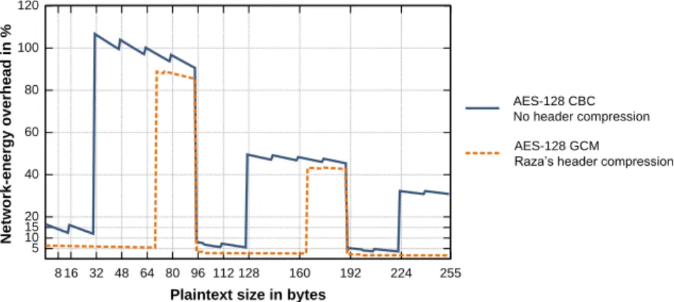
![Figure 5: Average (n=100) packet round-trip time for different plaintext sizes [1]](https://thumb-us.123doks.com/thumbv2/123dok_us/9782381.2469970/12.918.228.688.194.401/figure-average-packet-round-trip-different-plaintext-sizes.webp)
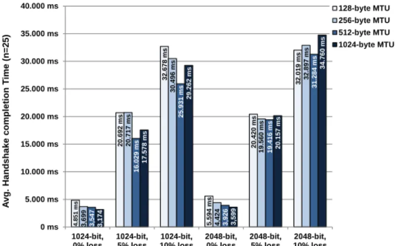
![Figure 6: Time to complete different types of DTLS handshakes [1].](https://thumb-us.123doks.com/thumbv2/123dok_us/9782381.2469970/14.918.262.655.195.458/figure-time-complete-different-types-dtls-handshakes.webp)
![Table 1: RAM and ROM usage by component [1, 2].](https://thumb-us.123doks.com/thumbv2/123dok_us/9782381.2469970/16.918.299.618.576.762/table-ram-rom-usage-component.webp)
![Table 2: Transaction time / energy consumption of DTLS handshake (2048-bit key) [1, 2]](https://thumb-us.123doks.com/thumbv2/123dok_us/9782381.2469970/17.918.209.700.394.575/table-transaction-time-energy-consumption-dtls-handshake-bit.webp)
![Figure 8: Current draw for a fully authenticated DTLS handshake [1, 2]](https://thumb-us.123doks.com/thumbv2/123dok_us/9782381.2469970/18.918.271.645.192.508/figure-current-draw-fully-authenticated-dtls-handshake.webp)
Related documents
mary care physicians, pediatricians, nurse practitioners, physician assistants, school nurses) to do oral health screening of young children during well-child visits, and
All statewide training courses are now available in iLearnOregon - the state of Oregon’s learn- ing management system.. Registration is made available to all state agencies,
A hostile or negative attitude toward people in a distinguishable group based solely on their membership in that group; it contains cognitive, emotional, and behavioral
The EIP membrane performances with different monomer concentrations at electrospray time of 30 min: (a) water permeance and MWCO, and (b) NaCl and EB permeance
Caspi, Rabins, Moffit, dan Stouthhamer-Loeber (1994) (dlm. Jan ter Laak, et.al., 2003) juga mengkaji delinkuen dengan personaliti mendapati tahap tinggi delinkuen diiringi
Therefore the plant was designed to use different water sources and different treatment processes: seawater (from the Westerschelde estuary) and integrated membrane system (IMS)
In this study, we have investigated the low Reynolds number and moderate Mach number flow over a tumbling flat-faced short cylinder with aspect ratio, (l/D = 1.5) using direct
Finally, a policy support system for the college stu- dents' entrepreneurship is constructed based on business cycle consisting of training, financing, supporting facilities,
