Multi-Projector Displays Using Camera-Based Registration
Ramesh Raskar
∗, Michael S. Brown
†, Ruigang Yang, Wei-Chao Chen,
Greg Welch, Herman Towles, Brent Seales
†, Henry Fuchs
Department of Computer Science
University of North Carolina at Chapel Hill
ABSTRACT
Conventional projector-based display systems are typically designed around precise and regular configurations of pro-jectors and display surfaces. While this results in rendering simplicity and speed, it also means painstaking construction and ongoing maintenance. In previously published work, we introduced a vision of projector-based displays constructed from a collection of casually-arranged projectors and display surfaces.
In this paper, we present flexible yet practical methods for realizing this vision, enabling low-cost mega-pixel dis-play systems with large physical dimensions, higher resolu-tion, or both. The techniques afford new opportunities to build personal 3D visualization systems in offices, conference rooms, theaters, or even your living room. As a demonstra-tion of the simplicity and effectiveness of the methods that we continue to perfect, we show in the included video that a 10-year old child can construct and calibrate a two-camera, two-projector, head-tracked display system, all in about 15 minutes.
CR Categories: I.3.3[Computer Graphics]: Picture/Image Generation -Digitizing and scanning, Display algorithms, View-ing algorithms; I.3.7 [Computer Graphics]: Three-Dimensional Graphics and Realism - Virtual reality; I.4.1 [Image Processing and Computer Vision]: Digitization and Image Capture -Imaging geometry, Camera calibration, Sampling, Scanning; I.4.8[Image Processing and Computer Vision]: Scene Analysis -Range data, Surface fitting, Tracking; B.4.2[Input/Output and Data Com-munications]Input/Output Devices -Image display.
Additional Keywords: display, projection, spatially immersive display, panoramic image display, virtual environments, intensity blending, image-based modeling, depth, calibration, auto-calibration, structured light, camera-based registration.
∗{raskar, ryang, ciao, welch, herman, fuchs}@cs.unc.edu †{mbrown,seales}@dcs.uky.edu
1
INTRODUCTION
The lure of building a single logical display from a set of individual light projectors is inspired by the promise of very high-resolution displays with large areas of coverage together with affordable components. Such large field of view dis-plays are traditionally created using a well-configured set of projectors so that they do not create keystoning and are physically aligned to match the neighboring projectors. Such panoramic displays for flight simulations, virtual reality and visualization create spectacular imagery [1, 2, 3, 4, 5, 6]. However, the physical construction of these idealized sys-tems requires considerable space and constant attention and adjustment by trained personnel. The large amount of com-puting/rendering power that is now available and ever in-creasing allows us to consider a different set of tradeoffs. With additional computation costs, we can design a gener-alized solution - one that accommodates display in normal rooms using a casual placement of projectors.
User
Projectors
Screen
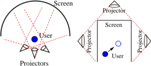
Figure 1: (a) Our display techniques allow for an arbitrary configuration of projectors and displays. (b) Example of arbitrary projector overlaps before calibration. (c) Viewer in the final display environment. (see color plate)
One central problem to be solved in achieving seamless imagery with multiple projectors is that of geometric regis-tration. Broadly, geometric registration is the alignment of image features on the target display surface across individual light-projector boundaries. Correct registration, together with correct image intensity blending of the overlapped im-age areas, makes these boundaries visually insignificant, and creates a powerful immersive effect for the viewer. The ef-fect is broken when the panorama contains seams or obvious gaps and overlaps.
Few panoramic display systems have explored the issue of maintaining compelling geometric registration between over-lapping projected images for a moving user. We achieve geometric registration by recovering a 3D representation of the display environment. This includes taking into account three critical components:
• theconfigurationof the set of projectors,
• thegeometryof the display surface,
Central to these geometric techniques is the use ofcameras to recover the 3D representation and calibrate the system. The projectors and cameras operate together as a tightly-coupled system to recover critical geometric information of the projectors and the entire display surface. The Office of the Future system [7, 8] originally introduced the idea of us-ing cameras to recover 3D displays surfaces and renderus-ing on them. We present new techniques that enable the sys-tem to maintain geometric registration and deliver seamless panoramic imagery. Figure 1 shows the kinds of geometry that our camera-based approach will allow: irregular display surfaces, arbitrarily-positioned (and overlapping) light pro-jectors, and a moving viewer. Our techniques do not require idealized display surface geometry and viewer/projector con-figurations, although we encompass these special situations, in some cases with improved efficiency.
The technical presentation begins with an application of computer vision techniques to calibrate the cameras and re-cover display surface and projector parameters. We then describe a two-pass rendering method for generating a per-spectively correct image on an irregular surface. We then detail issues withscalingthe system: repeating these proce-dures for a large number of projectors. The individual steps involved are direct, and yet unavoidable imperfections intro-duce errors in estimation of recovered parameters and lead to visible artifacts in projector overlaps.
Our approach provides ways to compensate for the prac-tical geometric errors that, left alone, lead to serious mis-registration. We introduce a surface mesh unification method to ensure the geometric continuity of the 3D global display surface model across projector boundaries. Finally, to address the relatively small registration errors that in-evitably remain after any parametric calibration, we present a new 2Dpost-rendering warpstep.
2
BACKGROUND
A common way to represent the many components of the panoramic display problem is to consider a world coordinate system (WCS) defined in the viewer’s physical space to en-compass viewer position and a representation of the screen surface. Representations of each of the components of the system are expressed within this WCS: the 3D model to be rendered, models of the light projectors, models of the cam-eras, and a model of the display surface. At the minimum scale, the problem is to consider a single camera and projec-tor. Scaling the environment means that the number of pro-jectors and cameras are increased in order to obtain higher resolution and larger areas of physical screen coverage. Any method to create a unified display from camera/projector components must be based on the geometric relationships between component models.
2.1
Geometric Relationships
The display surface and viewer physical environment defines the WCS, and each projector and camera is modeled as a perspective projection device in the WCS. The perspective transformation relates the 2D pixel coordinates (image pixels for the camera, frame buffer pixels for the projector) to the 3D WCS. Perspective transforms can be represented with a pinhole camera model. The pinhole model includes intrin-sic characteristics, such as the image center and the focal length, as well as the extrinsic characteristics, which locate the optical center and 3D orientation of the projective de-vice.
The full-scale panoramic image display problem is to com-pute images for the frame buffers of each projector such that the images combine properly on the display surface to pro-duce geometrically correct, seamless imagery for the viewer. When we assume an idealized and completely known geom-etry for display configuration (all components), the problem of computing the correct imagery for the viewer can be com-pletely specified using two mappings.
The first mapping uses the geometric relationship among the viewer, 3D model to be rendered, and the display surface to determine the intensity values that must be assigned to each point on the display surface. The second mapping uses the exact relationship between each projector pixel and the display surface point it illuminates in order to assign the appropriate pixel intensities to each projectors’ frame buffer. When the complete geometry is known exactly, the pro-jections from all the frame buffers illuminate the scene so that the viewer sees the correct imagery and the problem of generating large-scale panoramic imagery is solvable. But an understanding of the geometry is not enough to create a practical system. Challenges arise when large-scale systems are coupled with an inaccurate knowledge of geometry, in-complete or inaccurate camera/projector models, and when performance becomes a concern.
User Screen Projectors Projector Projector Projector User Screen
Figure 2: Examples of panoramic image display environ-ments
2.2
Related Work
Although the idealized representation of the panoramic dis-play problem can be stated quite directly, the implemen-tation of a real system faces the practical issues of impre-cise geometry, aliasing, blending and many sources of mis-registration. There are a variety of ways to cope with these issues, and many panoramic displays with and without user head-tracking have been developed. The majority of the sys-tems, such as those from Panoram Technologies [5] and Tri-mension Systems [4], create images for a single ideal viewer location, or “sweet spot”. Specifically, Trimension [4] uses three overlapping projectors to project images on a rigid cylindrical screen. The light projectors are aligned symmet-rically so that each overlap region is a well-defined rectangle (Figure 2a). Flight simulators have been using a similar technique for a long time. Omnimax [2] and ARC domes [6] immerse the user in high resolution wide-field images using a single projector and dome shaped surfaces. Using rear-projection and head-tracking, the CAVE [1, 9] enables interactive and rich panoramic visualizations. The setup is a precise and well designed cube-like structure (Figure 2b). The CAVE assumes that the display surface and projector geometries are known and are fixed a priori in a specific configuration. Geometric registration is obtained by care-fully ensuring that the physical configuration matches the design.
The Office of the Future [7] suggests using arbitrary day-to-day surfaces for display purposes and rendering
perspec-tively correct images for a moving user on them. That sys-tem demonstrated ideas on a small-scale syssys-tem, where the idealized geometries and models are accurate enough to pro-duce acceptable results. Our methods carry that small-scale work forward, scaling to many cameras and projectors and presenting new techniques that are necessary to obtain the performance and the geometric registration required to de-liver seamless panoramic display.
The issues of maintaining geometric registration between projected images for a moving user have not been fully ex-plored by current projector-based systems. However, many authors have presented techniques to create panoramic mo-saics of images taken with a camera. Typically, the images are taken with a camera mounted on a rotating tripod. If there is no strong motion parallax, the images are “stitched” and smoothly blended to create a single panoramic image. Earlier stitching methods required pure (horizontal) panning motion of the camera [10, 11]. This is analogous to current multi-projector systems that allow only side-by-side overlaps and align two projectors at a time.
Newer panoramic image mosaicing techniques allow un-controlled 3D camera rotations [12, 13] by representing each image with a 3-parameter rotational model or sometimes with more parameters. This allows mosaicing of images taken with even a hand-held camera. We extend this con-cept and represent the image displayed by each light pro-jector by a sequence of two perspective projection transfor-mations. The panoramic imagery is created using arbitrary projection overlaps. Most of the camera image mosaicing techniques deal with the difficult problem of computing im-age feature correspondences. We reduce this problem by using active structured light.
With regard to intensity blending of overlapping projected images, some popular techniques are described in [14, 12]. Section 4.3 details how we modify similar techniques for our multi-projector display environment.
3
SINGLE PROJECTOR DISPLAY
As background for the discussion of multi-projector system calibration in Section 4, this section details the three fun-damental calibration steps for a single projector display and includes a brief on the generalized 2-pass rendering technique used as a basis of our work.
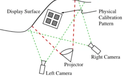
Physical Calibration Pattern Display Surface Projector Right Camera Left Camera
Figure 3: Configuration for single projector. Our calibration procedures are based on using a stereo camera pair that is positioned on a wide baseline with each oriented to observe the entire projector illuminated surface. Figure 3 illustrates this layout. Step oneof the procedures involves calibration of the camera pair using a physical cal-ibration pattern. Details of the physical calibration pat-tern are discussed in Section 6 and the accompanying video. Calibration step two involves estimation of display surface geometry and step three evaluates projector intrinsic and
extrinsic parameters. These methods are based on stan-dard computer vision techniques and systematically build on each other. The camera pair and calibration pattern are not needed during rendering operation and can be retired once the calibration procedures are complete.
3.1
Camera Calibration
To calibrate the camera pair, we position a 3D calibration pattern with spatially-known feature points within the in-tersection of their view frusta. By extracting feature points in the 2D camera images corresponding to known 3D points on the calibration pattern, we can determine the 3×4 pro-jection matrix ˜P for each camera based on the perspective equation:
[U V S]T = ˜P[x y z1]T (1)
The perspective equation maps a 3D point (x, y, z) in ob-ject space to a 2D point (u, v) in camera image space, where (u, v) = (U
S, V
S). The projection matrix ˜P, determined up to a scale factor, represents a concatenated definition of the camera’s intrinsic and extrinsic parameters assuming a pin-hole optics model. With six or more correspondences be-tween the calibration pattern and camera images, the 11 unknown parameters of ˜Pcan be solved using a least-squares method [15]. Note, we do not explicitly solve for the intrin-sic and extrinintrin-sic parameters of the camera, instead we solve for ˜P directly; however, the intrinsic and extrinsic can be obtained by a decomposition of ˜P.
3.2
Display Surface Estimation
After independent calibration of each camera, we can eval-uate the geometry of the display surface using triangula-tion techniques based on correspondences extracted from the stereo image pair. Correspondences in the images are easily determined since we can use the projector to sequentially illuminate point after point until we have built a 3D point cloud representing the display surface. By binary-coding the projector illuminated pixels, we can efficiently determine the stereo-correspondences. The process of projecting patterns so that they can be uniquely identified by a camera is also known as an active structured light technique.
This 3D surface representation, which is in the coordinate frame of the physical calibration pattern established in step one, is then reduced into a mesh structure in projector image space using 2D Deluanay triangulation techniques.
3.3
Projector Calibration
As a result of the surface extraction process, for each pro-jector pixel (u, v), we now have a corresponding illuminated 3D surface point (x, y, z). Using these correspondences we can solve for the projector’s projection matrix ˜P as we did for the cameras.
A problem arises when the 3D points of the display sur-face are co-planar. In this case, the least-square method is degenerate due to the depth-scale ambiguity of viewing pla-nar points. This means there exists a family of solutions. To develop a unique solution in this case, we add surfaces into the scene and repeat the surface extraction procedures of Section 3.2 solely for the purpose of eliminating this ambi-guity. Once this solution is affected, the introduced surfaces are removed from the display environment.
3.4
2-Pass Rendering Algorithm
To render perspectively correct imagery on irregular sur-faces, we use a two-pass rendering method described in [7]. In the first pass, the desired image for the user is computed and stored as a texture map. In the second pass, the tex-ture is effectively projected from the user’s viewpoint onto the polygonal model of the display surface. The display sur-face model, with the desired image texture mapped onto it, is then rendered from the projector’s viewpoint. This is achieved in real-time using projective textures [16]. The rendering cost of this two-pass method is independent of complexity of the virtual model.
From a practical implementation standpoint, aliasing ar-tifacts of the projective texture step can be reduced by com-puting a view frustum with the image plane parallel to the best-fit plane representation of the display surface.
4
MULTIPLE PROJECTOR DISPLAY
The remainder of this paper will address the issues in scaling the calibration and rendering techniques from a single to a multi-projector system.
First, to calibrate multiple projectors we repeat the proce-dures discussed in Section 3, but then we must re-register the display surface definitions and projector calibrations for the entire system to a common world coordinate space (WCS). These registration methods are described in Sections 4.1 and 4.2, while Section 4.4 discusses re-registering the viewer tracker data.
Second, display surface regions where multiple projectors overlap are noticeably brighter because of multiple illumi-nation. We correct for this by attenuating projector pixel intensities in the overlapped regions. Our current intensity blending technique are explained in Section 4.3.
4.1
Surface Mesh Registration
When multiple projectorsPiand stereo camera pairsCiare used, it is generally necessary to move the physical calibra-tion pattern so that it can be viewed by the different camera pairs. As described in Section 3.2, parameters for projec-torPi and the corresponding section of the display surface meshDiare defined in the coordinate system of the calibra-tion pattern used in the camera pairCicalibration step. To render seamless images, we first register all sections of the display surface mesh into a common WCS.
Registering data represented in multiple coordinate frames into a common frame is a classic computer vision and graphics problem that involves solving for the rigid transfor-mation given by:
Di(k) =Ri∗Di+1(k) +t~i (2)
whereRi is a 3×3 rotation matrix,~tiis a 3×1 translation vector andDi(k) andDi+1(k) are corresponding 3D points in the two frames of reference. To computeRand~t, we use the Lagrangian multipliers method which solves the least-square minimization problem, ||Di(k)−(RiDi+1(k) +~ti)||2 subject to the constraint that Ri is a unitary matrix, i.e.
RiRTi =I. This method is outlined nicely in [17].
The challenge in solving forRand~tin most applications is finding the correspondence between 3D points. We easily find these corresponding points inDi+1 withDi using the same binary-coded structured light methods used for surface extraction and projector calibration. The camera pair Ci
observes a set of projector pixels from projectorPi, but can also observe a subset of the pixels projected by adjacent projectorPi+1. Similarly, camera pairCi+1 observes pixels projected by Pi+1 and a subset of the pixels of projector Pi. The common set of 3D points that one camera pair can observe from both projectors is the correspondence set necessary to solve (2) and thus register the display surface data of one projector to another.
4.2
Projector Registration
Projection parameters of the projectorsPiare based on their display surface Di as described in Section 3.3. After the display surface meshes have been registered by applying rigid transforms, we recalculate the projector’s projection matrix.
4.3
Projector Overlap Intensity Blending
Regions of the display surface that are illuminated by mul-tiple projectors appear brighter, making the overlap regions very noticeable to the user. To make the overlap appear seamless we use alpha blending techniques. We create an alpha-mask for each projector, which assigns an intensity weight [0.0−1.0] for every pixel in the projector. Weights of all projected pixels illuminating the same display surface point should add up to unity. The weight is additionally modified through a gamma lookup table to correct for pro-jector non-linearities.
To find the alpha-mask, we use a camera to view the over-lapped region of several projectors. We form a convex hull
Hi in the camera’s image plane of observed projector Pi’s pixels. The alpha-weightAm(u, v) associated with projector
Pm’s pixel (u, v) is evaluated as follows:
Am(u, v) =
αm(m, u, v)
P
iαi(m, u, v)
(3) whereαi(m, u, v) =wi(m, u, v)∗di(m, u, v) andiis the index of the projectors observed by the camera (including projec-torm).
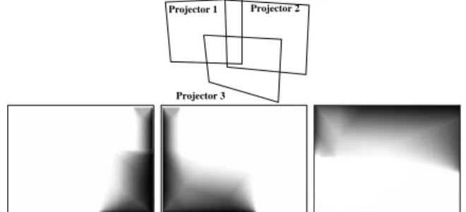
In the above equation,wi(m, u, v) = 1 if the camera’s ob-served pixel of projectorPm’s pixel (u, v) is inside the convex hullHi; otherwise wi(m, u, v) = 0. The termdi(m, u, v) is the distance of the camera’s observed pixel of projectorPm’s pixel (u, v) to the nearest edge of Hi. Figure 4 shows the alpha masks created for three overlapping projectors.
Projector 2 Projector 1
Projector 3
Figure 4: The top image shows the overlap position of three projectors. The bottom images show the alpha masks cre-ated for projectors 1, 2, and 3 using our algorithm.
Similar feathering techniques are used to mosaic multiple images taken by a camera into a single panoramic image [18]. However, such a target 2D panoramicimagedoes not
exist when projector images are blended on (possible non-planar) display surfaces. Hence we use the 2D image of the display surface taken from a calibration camera and compute the intensity weights in this 2D camera image space. We transformed this alpha-mask in camera space into projector image space by using our 2-pass rendering technique. With a fixed alpha-mask for each projector, we simply render a textured rectangle with appropriate transparency as the last stage of the real-time rendering process.
4.4
Tracked Viewer Registration
The user location is measured by an infrared tracking de-vice. To use the tracker readings, we need to compute the transformation between the coordinate system of the track-ing system and the WCS defined by the physical tion pattern. Therefore, before moving the physical calibra-tion pattern from our reference projector, we also find the correspondences between four 3D points on the calibration pattern in calibration pattern coordinates and tracker sys-tem coordinates. We again use the Lagrangian multipliers method to find the rigid transformation between tracker co-ordinate space and display WCS.
5
NEW TECHNIQUES
Errors in tracked user location cause no geometric registra-tion problems between projectors as long as all rendering processes are fully synchronized. However, errors in the es-timation of the display surface and the camera/projector parameters are critical. When these errors are small, the display is seamless. When the errors grow, the display be-comes discontinuous where projectors overlap. Methods for addressing second-order errors such as for radial lens dis-tortion and non-linear bundle adjustment to improve the global estimate of the camera/projector calibration can re-duce the average mis-registration error, but our experiments have shown that radial distortion and bundle adjustment improve estimates only marginally, and do not prevent the viewer from perceiving mis-registrations in large-scale envi-ronments.
Therefore, to yield acceptable visual results we need to address the two primary sources of error - display surface estimation and projector calibration. We next review these error terms and then present new calibration and rendering techniques for preserving a seamless display.
5.1
Display Surface Errors
Display surface estimation is dependent on calibrated cam-eras and piecewise-registered 3D points that are connected into meshes. Small errors that are present in camera cali-bration are magnified as errors in the final computed display surface, resulting in an erroneous display surface. These errors are attributed to the following operations: display surface estimation include initial camera calibration from the calibration pattern, which requires feature detection and camera-parameter estimation; feature detection and stereo correspondence from structured light techniques; recovery of 3D coordinates using triangulation; coordinate frame regis-tration of meshes by estimating a rigid transformation to bring them into alignment. Because the final display surface will never be exact, we have developed techniques to lessen the effect of display surface errors on the final rendered im-agery.
5.2
Projector Calibration Error
Projector calibration is dependent on the 3D display surface points that are reconstructed by the camera system. The re-lationship between the 3D points and the 2D pixel locations that illuminate those points is the basis for calibration. Be-cause of errors in the computed location of the 3D points, the projection matrix for light projectors does not map the 3D display surface points exactly onto their 2D pixel locations. The re-projection error is directly dependent on errors in the 3D display surface reconstruction; errors are small when only one or two projectors and cameras are used, but grow as the system scales. Due to these errors in the projection matrices of light projectors, we have developed an image-based technique to lessen the effect of re-projection errors on the final rendered imagery.
5.3
Geometric Error Compensation
In order to create geometrically seamless imagery for the viewer, we compensate for errors in 3D (display surface) and 2D (calibration of projector in the form of a projec-tion matrix from 3D display-space to the 2D frame buffer). Specifically, we base our methods on two objectives:
• neighboring projectors should use exactly the same rep-resentation of the display surface geometry
• the projection matrix for a light projector should map 3D screen points onto the exact 2D pixels that illumi-nated them during the structured light process If the overall environment reconstruction process was accu-rate, both objectives would automatically be satisfied. How-ever, because it is inevitable that inaccuracies exist, our ap-proach is to enforce geometric continuity in the registered display surface in the projector overlap regions, and to guar-antee geometric fidelityof the final imagery illuminated by the projector. In the next two section we present two tech-niques for accomplish these goals.
5.4
Surface Mesh Unification
The objective is to create a single representation of the dis-play surface from the multiple meshes recovered by different stereo camera pairs. A single unified display surface will not have discontinuities in regions where projectors overlap, reducing geometric mis-registrations. The rigid transforma-tion applied to each of the meshes brings them into near alignment, but discontinuities still exist due to errors in the 3D recovery.
Specifically, two distinct but overlapping meshes are brought into approximate alignment in a common coordi-nate system using the set of corresponding points that over-lap between the two and are seen by the stereo camera pair (described in Section 4.1). Stereo pairs Ci and Ci+1 may both see illuminated pixels from projectorsPiandPi+1, and such corresponding points are used for the alignment. After the rigid transformation to align the two meshes, however, 3D values assigned to the illuminated surface points byCi andCi+1do not agree. Agreement is necessary, and we en-force it through a smooth 3D transition algorithm to obtain display surface continuity.
Our present technique is similar to methods used to re-duce intensity discontinuities in composited images [14][18]. However, instead of weighting pixel intensities, we weight their associated 3D location. As with our intensity blending algorithm, we use a single camera from a camera pair to aid
00 00 00 11 11 11 0 0 0 1 1 1 00 00 11 11 00 00 11 11 00 00 11 11 00 00 00 11 11 11 00 00 11 11 00 00 11 11 00 00 00 11 11 11 00 00 11 11 00 00 00 11 11 11 00 00 11 11 00 00 11 11 00 00 11 11 00 00 00 11 11 11 00 00 00 11 11 11 00 00 11 11 0 0 0 1 1 1 000111 0 0 1 1 0 0 0 1 1 1 00 00 11 11 00 00 11 11 0 0 0 1 1 1 0 0 1 1 00 00 00 11 11 11 0 0 0 1 1 1 00 00 00 11 11 11 00 00 00 11 11 11 00 00 11 11 00 00 11 11 0 0 1 1 00 00 11 11 00 00 11 11 0000 0000 1111 111100001111 0000 0000 0000 1111 1111 1111 0000 0000 0000 1111 1111 1111 00 00 11 11 00 00 00 00 00 11 11 11 11 11 0000 1111 00 11 000 111 000 000 000 111 111 111 00 00 11 11 00 00 00 00 11 11 11 11 0 0 0 0 1 1 1 1 00 00 11 11 0 0 1 1 0 0 0 1 1 1 00 00 00 00 00 11 11 11 11 11 Di Di+1 D’i D’i+1
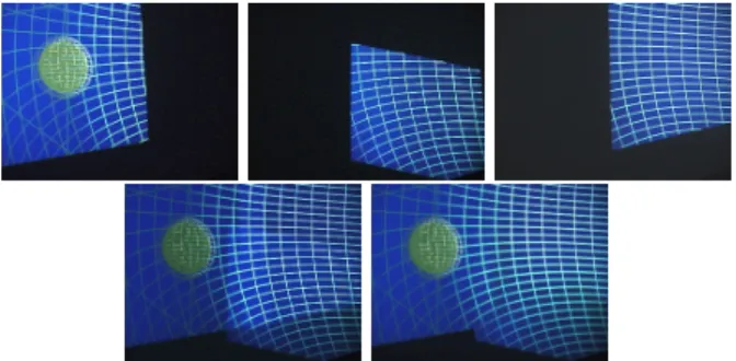
Figure 5: 3D points of the two display surfaces do not agree after registration with a rigid transformation so we use weighted averaging to obtain geometric continuity across the surfaces. (see color plate).
with the averaging. The algorithm, which we term surface mesh unification, works as follows:
Let Mi(u, v) be the 3D point associated with projector
P’s pixel (u, v) seen by camera pairCi. The new “weighted” assignment of projector P’s 3D pointM(u, v) is evaluated as follows: M(u, v) =
P
jMP
j(u, v)dj(u, v) kdk(u, v) (4) where j and k are the index of cameras pairs that have viewed this projector pixel. The termdi(u, v) is the distance of the observed projected pixel (u, v) ofP to the nearest in-visible (black) pixel defined in the in camera spaceCi.Using this weighted averaging technique, we obtain new display surfaces D0i that have geometric continuity. Note that while the surface is continuous, it no longer represents the true surface. We denote the modified surface points by
M0 to distinguish them from the true surface points, M. Figure 5 shows an overview of the algorithm for a simple case of unifying two meshes. The same technique is used when more than two meshes partially overlap.
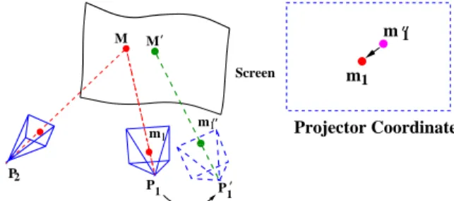
00 00 00 11 11 11 0 0 1 1 2 P M Screen P P 1 1 m1 M m1 ’ ’’ ’ Projector Coordinate 1 m1 m’’
Figure 6: (a) Error in display surface estimation and projec-tion matrix P1 creates mis-registration. (b) Partial correc-tion using a post-rendering warp.
Using Di0 we now recompute the projection matrix for the corresponding projector, as described in sections 3.3 and 4.2. The result is a new projection matrix correspondingly denotedPi0. As shown in Figure 6 this new projection ma-trix maps the modified 3D surface pointsM0 onDi0 to the projector pixelsmthat illuminated them.
5.5
Post-rendering Warp
It is important to realize that because the transformation fromMtoM0is non-rigid, the projection matrixPi0for each projector cannot exactly map the pointsM0 tom. Instead, the projection matrixPi0maps the pointM0to the distorted locationm00. In this case for projectors 1 and 2,
m001 =P10M0 and m
00
2 =P20M0. (5)
What one would really like is the non-linear projective function that directly maps M0 to m. This function could be determined by some other means, but the result could not be implemented using the single linear projection ma-trix common in conventional graphics hardware. We achieve this projective function in real time by first usingP0 as the traditional linear projection matrix, and then following this with a 2D post-rendering warp that mapsm00tom. The 2D warp is based on a dense grid of sampled points from the structured light process.
The texture-map implementation of this warp loads the image generated with projection matrix Pi0 into texture memory. The post-rendering warping is achieved using mul-tiple textured triangles. This resultant image is projected by the projector. All the warping operations, including 2-pass projective texture rendering to create an image and the 2D post-rendering warp, are fixed for given display sur-faces, projection matrices and re-projection errors. Hence they are established during pre-processing and loaded in a display list. The cost of this post-rendering warp remains fixed for given display surface and re-projection errors. It is independent of the graphics virtual model being rendered.
There are two important notes to make. First, it is dif-ficult to compute explicit projector pixel correspondences, such asm1 and m2. The correspondence is implicitly cal-culated by observing a dense grid of projected pixels. The tessellated display surface geometry is simplified to improve rendering speed during second pass of the two-pass rendering method. We are investigating methods to simplify the num-ber of triangles used during the post-rendering warp. Sec-ond, the projection matricesPi0 that are actually computed for each projector use the 3D surface points from the uni-fied surface meshD0i, which have been unified as described above. The computation of the unified surface mesh and the post-render warp are done only once and can therefore be implemented in real-time; the two techniques are closely linked to one another.
Mesh unification and the 2D post-rendering warp meet the two desired objectives: neighboring projectors should use exactly the same representation of the display surface ge-ometry, and that the projection matrix for a light projector should map 3D screen points onto the exact 2D pixels that illuminated them during the structured light process. By applying these novel techniques we can guarantee seamless geometric registration between overlapping projected images even when the estimated display surface and projector pa-rameters have large errors.
6
IMPLEMENTATION
The system setup includes five 1024×768 resolution SHARP LCD projectors and multiple JVC and Pulnix 640×480 res-olution camera. The projectors are ceiling mounted approxi-mately three to four meters from the display surfaces. These projectors are casually positioned with multiple overlapping regions to produce a 180 degree field of view when the user is in the display center.
Thecalibration of the system (i.e., evaluation of camera and projector parameters and display surface estimation) is done once as a pre-rendering step. This is accomplished us-ing a 0.6 meter cube that we constructed as our physical target pattern and a Dell NT workstation equipped with OpenGL graphics, Matrox Meteor II frame grabbers and Matlab software. The equipment is first used to capture the images of the physical target pattern and calibrate the cameras. Next, the workstation performs the
structured-light projection and analysis, controlling one projector and a stereo camera pair at a time. The stereo correspondences acquired by projecting structured light form the dataset needed for projector calibration, display surface reconstruc-tion and unificareconstruc-tion, post-warp mesh generareconstruc-tion, and alpha-mask generation. The actual processing for these steps is done off-line using Matlab.
The required sampling density of the structure-light pat-terns depends on the complexity of the display surfaces and the need to accurately locate the edges of overlapping pro-jectors for alpha-mask generation. For our purposes, we used sampling density of every 8th and every 32nd display pixel. By binary encoding the structure-light, this process can be parallelized and we are able to project and recover 16×12 correspondence points simultaneously. The complete opera-tion for display surface recovery and light projector parame-ter estimation takes approximately 15 minutes per projector at the highest sampling density and less than one minute for the lower sampling density.
A moving user is tracked using an Origin Instruments’ DynaSight(TM) infrared tracker [19]. The user wears a set of infrared LED beacons provided with the tracker. Tracker readings are acquired, processed (low-pass filtered and trans-formed into the WCS) by a Dell NT workstation before being dispatched in a network packet to the SGI image generation host.
The graphics rendering is done on an SGI InfiniteReality2 for each projector using the OpenGL API. While our ren-dering pipeline has additional computational cost due to the image warping steps, this cost is fixed and is independent of the rendered scene complexity.
Figure 7 shows a portion of our setup with three projec-tors forming a seamless panoramic image. The accompany-ing video shows the projection environment and real-time operation on irregular and planar surfaces with a tracked user. In addition, the video demonstrates how a non-expert user can easily and quickly setup and use a two projec-tor, head-tracked display. More images are available at http://www.cs.unc.edu/Research/stc/Seamless/.
Figure 7: The top set of images show the individual con-tribution of three projectors. The bottom two images show the projectors without and with alpha-blending. (see color plate)
7
PERFORMANCE FACTOR
We have presented a general solution for creating a large area display from many projectors where the display surface can be irregular. The methods incorporate the case where a head-tracked user views the display. The techniques for this most general case can be simplified under certain conditions
such as when the viewer is static rather than moving, or when the display surface is known to be planar.
7.1
Static User
Display systems with only a single “sweet spot” are com-monly used because either the application guarantees that the user will always stay in a single location (i.e., flight sim-ulator) or that many people will view the images simulta-neously from or near the correct position, as in domed dis-plays such as the Omnimax [2]. The relationship between de-sired image and projected image for each projector, i.e., the viewer-to-display mapping function, needs to be computed only once and subsequently remains fixed for that location. This mapping function can be obtained directly by us-ing a camera to represent the viewer at a given location. The camera observes points illuminated by projectors in the display environment, establishing viewer-to-display cor-respondences. A detailed implementation of this method is described in [20]. Using this technique, the rendering pro-cess has two stages; (1) compute the desired image and load it into texture memory, and (2) warp the texture via the viewer-to-display mapping to produce the correct imagery. Intensity blending of overlapping projectors is handled as in Section 4.3. This special case avoids explicitly solving for 3D parameters or the additional cost of the third-pass post-rendering warp, but limits the user to one position in the display environment.
7.2
Planar Surfaces
Surround screen displays can be easily created with multi-ple planar walls with a single projector illuminating a single planar surface. Examples of such systems include the CAVE [1, 9] and Trimension’s Reality Room[4]. The latter uses cylindrical screens, but the section of the screen illuminated by each projector is approximated by a plane.
In case of irregular surfaces, the warping function needed in order to produce correct imagery must be expressed us-ing a per-pixel mappus-ing. In practice, this is accomplished with the two-pass algorithm outlined in this paper. When every projector illuminates a planar surface, a single-pass rendering algorithm can achieve the same geometrically reg-istered result at less computational expense. Specifically, the planar constraint allows a single projector’s imagery to be expressed as acollineationwith the planar surface, which is a 3×3 matrix that is updated as the user moves. Neighbor-ing projectors are also related by a 3×3 collineation. The special planar geometry allows for a rendering method that does not incur additional computational costs while staying geometrically registered [21]. The video shows results for five projectors rendering onto two planar walls.
8
FUTURE WORK
Although we have addressed how to remove many of the geometric constraints involved in panoramic display systems, this is only a basic framework. There are several important issues that we have not fully addressed in this work that require further research:
• arbitrarily large numbers of projectors
• automatic system calibrationwithout the need for a physical calibration pattern or human intervention
• error sensitivity analysis and the quantifiable im-pact on rendering accuracy
• detailed projector colormetrics and methods for improving photometric seamlessness
• viewer-dependent photometrics including the is-sues of user location, surface orientation and intensity distribution, and surface inter-reflections
• synchronizationof rendering pipelines.
One can also extend our methods to display imagery for multiple tracked users or to display stereo imagery by ren-dering for both eyes. In stereo displays, traditionally, left and right eye images are projected by the same projector. Using the geometric registration techniques, we can even use two different sets of projectors (with different polarization, for example) to render for left and right eye.
9
CONCLUSION
In this paper we have presented techniques for building a scalable panoramic display device from multiple, casually-positioned light projectors. We maintain geometric regis-tration of the overall panoramic display; employing cameras forrecoveringdisplay surface and light projector geometries rather thanimposinggeometric constraints into the overall display setting. This integration of cameras into the initial-ization phase of the system and the techniques for maintain-ing registration in the face of errors leads to our primary contributions:
• Geometric registrationand seamless imagery is pro-duced over a wide range of geometric configurations
• Generalized display configurations including sup-port for irregular display surfaces and a head-tracked, moving viewer
• Rendering efficiencies in special casessuch as for a static user or planar display surfaces
• Post-rendering warp and 3D surface unification
together compensate for inaccuracies in the extracted geometric representation
• Self-configurable display and projector geometries are enabled so that future systems can automate cali-bration and registration.
Based on these new techniques, we believe we have built and and demonstrated the very first panoramic display sys-tem using irregular surfaces for a moving user. Even though there is much work yet to be done, this “proof-of-concept” system previews future possibilities for high-resolution, wide field-of-view displays that are easy to set-up, use and main-tain.
10
ACKNOWLEDGMENTS
This research is supported by the National Science Foun-dation agreement ASC-8920219: “Science and Technology Center for Computer Graphics and Scientific Visualization”, Link Foundation, Intel Corporation, and the “National Tele-Immersion Initiative” sponsored by Advanced Networks & Services, Inc.
We would like to thank Gopi Meenakshisundaram, Aditi Majumder and David Marshburn for useful discussions and support. We also gratefully acknowledge John Thomas, Jim Mahaney and David Harrison in the design and assembly
of our test environment, and Todd Gaul for video editing support. A special thanks is also due Su Wen and 10-year old Sam Fuchs for their participation in the video.
References
[1] C. Cruz-Neira, D. Sandin, and T. DeFanti, “Surround-screen Projection-based Virtual Reality: The Design and Implemen-tation of the CAVE,” Aug. 1993.
[2] N. Max, “SIGGRAPH 84 call for Omnimax films,” Computer Graphics, vol. 16, pp. 208–214, Dec. 1982.
[3] K. Jarvis, “Real Time 60Hz Distortion Correction on a Silicon Graphics IG,”Real Time Graphics, vol. 5, pp. 6–7, Feb. 1997. [4] Trimension Systems Ltd. http://www.trimension-inc.com/. [5] Panoram Technologies, Inc. http://www.panoramtech.com/. [6] D. Bennett. Alternate Realities Corporation, Durham, NC
27703. Cited July 1999. http://www.virtual-reality.com/. [7] R. Raskar, G. Welch, M. Cutts, A. Lake, L. Stesin, and H. Fuchs,
“The Office of the Future: A Unified Approach to Image-Based Modeling and Spatially Immersive Displays,” inSIGGRAPH 98 Conference Proceedings, July 1998.
[8] R. Raskar, M. Cutts, G. Welch, and W. St¨urzlinger, “Efficient Image Generation for Multiprojector and Multisurface Displays,” inProceedings of the Ninth Eurographics Workshop on Render-ing, (Vienna, Austria), June 1998.
[9] Pyramid Systems. http://www.pyramidsystems.com/.
[10] E. Chen, “Quicktime VR - An Image-Based Approach to Vir-tual Environment Navigation,” inSIGGRAPH 95 Conference Proceedings, pp. 29–38, Aug. 1995.
[11] L. McMillan and G. Bishop, “Plenoptic Modeling: An Image-Based Rendering System,” inSIGGRAPH 95 Conference Pro-ceedings, pp. 39–46, Aug. 1995.
[12] R. Szeliski, “Video Mosaics for Virtual Environments,”IEEE Computer Graphics and Applications, vol. 16, pp. 22–30, Mar. 1996.
[13] H. Sawhney and R. Kumar, “True Multi-Image Alignment and its Applications to Mosaicing and Lens Distortion Correction,” inIEEE Comp. Soc. Conference on Computer Vision and Pat-tern Recognition (CVPR’97), 1997.
[14] P. J. Burt and E. H. Adelson, “A Multiresolution Spline with Applications to Image Mosaic,”ACM Trans. on Graphics, no. 2, pp. 217–236, 1983.
[15] O. Faugeras,Three-Dimensional Computer Vision: A Geomet-ric Viewpoint. Cambridge, Massachusetts: MIT Press, 1993.
[16] M. Segal, C. Korobkin, R. Widenfelt, J. Foran, and P. Haeberli, “Fast Shadows and Lighting Effects using Texture Mapping,” in
SIGGRAPH 92 Conference Proceedings, July 1992.
[17] R. Haralick and L. Shapiro,Computer and Robot Vision, vol. 2, ch. 14. Addison-Wesley, 1993.
[18] H. Shum and R. Szeliski, “Panoramic Image Mosaics,” Tech. Rep. MSR-TR-97-23, Microsoft Research, 1997.
[19] Origin Instruments Corporation. http://www.orin.com/. [20] R. Raskar, G. Welch, and H. Fuchs, “Seamless Projection
Over-laps Using Image Warping and Intensity Blending,” inFourth International Conference on Virtual Systems and Multimedia, (Gifu, Japan), Nov. 1998.
[21] R. Raskar. Olique Projector Rendering on Planar Surfaces for a Tracked User. http://www.cs.unc.edu/Research/stc/Oblique.