Citation: Zhou, Dajun, Shi, Minghui, Chao, Fei, Lin, Chih-Min, Yang, Longzhi, Shang, Changjing and Zhou, Changle (2018) Use of human gestures for controlling a mobile robot via adaptive CMAC network and fuzzy logic controller. Neurocomputing, 282. pp. 218-231. ISSN 0925-2312
Published by: Elsevier
URL: https://doi.org/10.1016/j.neucom.2017.12.016
<https://doi.org/10.1016/j.neucom.2017.12.016>
This version was downloaded from Northumbria Research Link: http://nrl.northumbria.ac.uk/33477/
Northumbria University has developed Northumbria Research Link (NRL) to enable users to access the University’s research output. Copyright © and moral rights for items on NRL are
retained by the individual author(s) and/or other copyright owners. Single copies of full items can be reproduced, displayed or performed, and given to third parties in any format or medium for personal research or study, educational, or not-for-profit purposes without prior permission or charge, provided the authors, title and full bibliographic details are given, as well as a hyperlink and/or URL to the original metadata page. The content must not be changed in any way. Full items must not be sold commercially in any format or medium without formal permission of the copyright holder. The full policy is available online: http://nrl.northumbria.ac.uk/policies.html
This document may differ from the final, published version of the research and has been made available online in accordance with publisher policies. To read and/or cite from the published version of the research, please visit the publisher’s website (a subscription may be required.)
Use of Human Gestures for Controlling a Mobile Robot
via Adaptive CMAC Network and Fuzzy Logic
Controller
Dajun Zhoua, Minghui Shia, Fei Chaoa,d, Chih-Min Lina,b, Longzhi Yangc, Changjing Shangd, Changle Zhoua
aCognitive Science Department, Fujian Provincal Key Lab of Brain-like Computing,
School of Informatics, Xiamen University, China
bDepartment of Electrical Engineering, Yuan Ze University, Taiwan. cDepartment of Computer and Information Sciences, Faculty of Engineering and
Environment, Northumbria University, NE1 8ST, UK.
dDepartment of Computer Science, Institute of Mathematics, Physics and Computer
Science, Aberystwyth University, SY23 3DB, UK.
Abstract
Mobile robots with manipulators have been more and more commonly ap-plied in extreme and hostile environments to assist or even replace human operators for complex tasks. In addition to autonomous abilities, mobile robots need to facilitate the human-robot interaction control mode that en-ables human users to easily control or collaborate with robots. This paper proposes a system which uses human gestures to control an autonomous mo-bile robot integrating a manipulator and a video surveillance platform. A human user can control the mobile robot just as one drives an actual vehicle in the vehicle’s driving cab. The proposed system obtains human’s skele-ton joints information using a motion sensing input device, which is then recognized and interpreted into a set of control commands. This is imple-mented, based on the availability of training data set and requirement of in-time performance, by an adaptive cerebellar model articulation controller neural network, a finite state machine, a fuzzy controller and purposely de-signed gesture recognition and control command generation systems. These algorithms work together implement the steering and velocity control of the mobile robot in real-time. The experimental results demonstrate that the proposed approach is able to conveniently control a mobile robot using virtual driving method, with smooth manoeuvring trajectories in various speeds.
Keywords: Mobile robot, mobile manipulator, intelligent control, human-robot interactions
1. Introduction
A conventional mobile manipulator typically consists of a mobile plat-form and a manipulator with multiple degrees-of-freedom (DOF), and thus it benefits the advantages of both components [1, 2, 3, 4]. In addition to saving human labors in traditional tasks like autonomous navigation, un-manned production lines, and environmental perception, mobile robots are more and more commonly applied to assist or even collaborate with hu-man beings to work in extreme or hostile environments for complex tasks [5], such as aerospace and deep-sea exploration [6, 5, 7]. Such assistance or collaboration requires effective and efficient natural interactions between humans and robots [8]. In addition, there is an appeal in more user friendly and natural way to control robots performing normal daily tasks along with the increasingly wider use of robots in people’s daily life, as conventional control methods depending on traditional input devices, such as keyboards, joysticks, or touch-screens, is inconvenient and unsuitable for those people lack of learning ability.
Human-robot interaction (HRI) is rapidly being established and devel-oped in this context as a technical discipline that studies the mutual commu-nication and understanding between humans and robots, and helps humans collect, manage, and handle information [9, 10, 11, 12, 13, 14]. A number of approaches have been proposed to control robots using human gestures. For instance, Pedersen and Kr¨uger defined five gestures used as control com-mands to guide the movements of mobile robots [15]; and a similar piece of work was also reported by Pentiuc et al. [16]. Wongphati [17, 18] used a set of body gestures to build a stationary of control commands for mobile robot control. Burger et al. [19] developed a mobile manipulator platform that can be controlled by speech commands and two-arm gestures. In addition, Yu et al. [20] applied hand gestures captured by a Leap Motion device to control humanoid robots. However, these studies constrain human gestures to fixed discrete patterns by connecting each of these symbolic commands to a particular robot action without the flexibility of quantitative control in real time.
This paper proposes a human gesture-based HRI method using multiple continuous human gestures to quantitatively control a mobile robot with a
multi-DOF manipulator, in an effort to address the identified challenge above. In particular, this paper implements the proposed idea by taking real driving gestures for normal vehicles to quantitatively control the mobile robot. This approach firstly capture the gestures using a motion sensing input device, “Microsoft Kinect”, thanks to its rich libraries in gesture recognition. Then, the interactions between a human demonstrator and the mobile robot is made through tele-manipulations. The surveillance videos, captured by a binocular camera mounted on the robot, are collected via wireless network transmissions in real time.
The proposed method, in contrast to the existing ones, is of more flex-ible control operations, which can be used in multi-person-operation tele-manipulation tasks. This is implemented by two separate gesture processing channels for steering, and velocity changing with the latter including gear shifting and accelerator/break pressing. The training data set for gear shift-ing gestures can be readily obtained by samplshift-ing human gestures and thus an adaptive Cerebellar Model Articulation Controller (CMAC) network is applied in this work for gear shifting gesture classification [21]. However, differently, it is difficult to obtain training data for the steering and veloc-ity control simultaneously, because such type of training data can only be obtained by simultaneously sampling the mobile robot’s moving direction and velocity and their corresponding gestures from the human demonstra-tor. Note that a fuzzy inference system can take the advantage of human driving experiences in the from of fuzzy rules to solve such problem [22, 23]. Thus, the major contribution of this work is a gesture-based control system which integrates a CMAC and a fuzzy controller (Sections 2.2, 2.3 and 2.4) using human gestures that are similar to practical driving gestures to control a mobile robot in an efficient and user-friendly way.
The remainder of this paper is organized as follows. Section 2 details of the proposed HRI system, including steering control and the velocity con-trol. Section 3 elaborates the experimental setup and discusses the detailed experimental results. Section 4 concludes the work and points out important future work.
2. The Porposed Approach 2.1. Overall Control Procedure
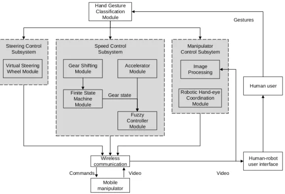
The entire control architecture of the mobile robot system is shown in Fig-ure 1. In particular, a human user generates actual driving gestFig-ures in front
Hand Gesture Classification Module Virtual Steering Wheel Module Gear Shifting Module Finite State Machine Module Accelerator Module Fuzzy Controller Module Image Processing Wireless communication Mobile manipulator Robotic Hand-eye Coordination Module Steering Control Subsystem Speed Control Subsystem Manipulator Control Subsytem Human-robot user interface Human user Gestures
Commands Video Video
Gear state
Figure 1: The flowchart of the entire architecture. The architecture consists of three control subsystems: steering control, velocity control, and manipulator control.
of a motion sensing input device, i.e., Microsoft Kinect 2, which captures the skeleton information of the human gestures. Then, the skeleton information is used to control the mobile robot equipped with a robotic hand-eye coor-dination system. The proposed approach is mainly comprised of one gesture recognition module and three control subsystems: (1) the mobile platform’s steering control, (2) the mobile platform’s moving velocity control, and (3) the manipulator’s control. All these subsystems take human gestures as in-puts and generate control values or control commands to the mobile robot system accordingly as introduced below and detailed in Sections 2.2, 2.3 and 2.4.
• The steering control subsystem utilises driving gestures for actual ve-hicles to control the robot’s direction. A human user performs the basic gestures by holding a virtual steering wheel. The user rotates a virtual steering wheel to change the mobile robot’s moving direction. The rotation gestures are translated to the mobile robot’s direction values by constantly considering the positions of the hands of the user. In contrast to other existing approaches, the proposed steering control method supports quantitative information and thus produces smooth control results.
• The moving velocity control subsystem takes the values of the two con-trol components from actual vehicles, including “transmission gears” and “break/accelerator”. The human user performs gear shifting ges-tures in front of the Kinect device; a transmission gear shift module is created to recognize the human gestures to generate commands of “shift-gear-up” or “shift-gear-down”. A finite state machine module not only records the current gear state, but also adjusts the gear state based on the commands from the transmission gear shift module. The accelerator and break functions of a vehicles are simulated by “pushing-down” and “pulling-up” the operator’s two hands simulta-neously. The current gear state values and the position values are sent to a fuzzy controller, which produces velocity commands for the mobile platform using a pre-defined fuzzy rule base based on expert knowledge. Similar to the steering control, this moving velocity control method also exhibits a quantitative property for smooth control performance.
• The manipulator control subsystem uses a predefined arm gesture to inform the robot’s hand-eye coordination system to perform tasks of
ob-ject capturing. The robot’s vision system captures the entire workspace of the robot’s manipulator which facilitates the identifying the target object. Once the target object is found, the robot’s hand-eye coordi-nation system automatically performs capturing movements using the manipulator. The implementation details of this subsystem is beyond the focus of this paper and thus omitted due to space limit but can be found in the work of [24, 25].
The states of the robot is monitored by a human-robot interaction inter-face as detailed in Section 2.5, through which the human user can watch the control performance and also the object capturing actions performed by the manipulator.
2.2. Gesture Recognition Module
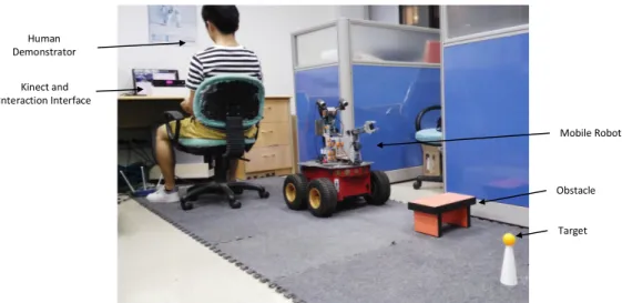
The environment of the mobile robot is shown in Figure 2. A human demonstrator sits in front of the Kinect device and watches the human-robot interaction interface. An obstacle and a target object are placed in the robot’s workspace. The gestures of the human user are used for the steering control, velocity control and manipulator control subsystems. The communications between the human demonstrator and the mobile robot are made through wireless network connection.
The proposed approach uses human driving gestures to control a mobile manipulator by manoeuvrings the mobile platform and performing object-capturing function, which is usually taken as a very challenging task. There-fore, the Microsoft Kinect sensor is employed in this work for gesture cap-turing to reduce the implementation complexity due to its rich built-in li-braries. Thanks to this, the skeleton information of human body can be readily captured, which is sufficiently accurate for robot control. In addi-tion, as illustrated in Figure 2, the human demonstrator sits in front of the Kinect device, and only human arm and hand gestures are used to control the robot. Such ready-made skeleton information and the fixated gesture sampling environment jointly reduce the complexity of gesture recognition tasks.
For each sampling unit, the Kinect generates a position vector, −−→body, of the key points of a human body, and particularly 25 points are used in this work. The human gesture classification model identifies each sampled human gesture, and assign the gesture to the corresponding subsystem. In particular, the Euclidean distance,d, between a human user’s two hands is used to check
Human Demonstrator Kinect and Interaction Interface Mobile Robot Obstacle Target
Figure 2: The experimental environment. The human demonstrator sits in front of the Kinect device and watches the human-robot interaction interface. The communications between the human demonstrator and the mobile robot are made through wireless network connection. An obstacle (i.e., the orange and black object) and a target object (i.e., the yellow ball) are placed in the robot’s workspace.
Activated Module Distance Range
Steering Control Module 250mm < δ < 500mm
Velocity Control Module δ >1,000m
Manipulator Module δ <100mm
Table 1: The setup of the hand classification module.
the gesture’s type. The positions of the two hands are obtained from −−→body. Simple determination rules are pre-defined for gesture type identification as follows:
1. Steering control gestures: the human performs the basic gestures for holding a virtual steering wheel; thus, d need to fall in the range [250mm,500mm].
2. Velocity control gestures: the human performs gear shifting gestures;
d is larger than 1,000mm.
3. Manipulator control gestures: the human user straightens the arms and holds the hands together in front of chest; thus, d is less than 100mm. These gesture classification rules are summarized in Table 1. In order to achieve better classification accuracy, three key points regarding gesture
recognition are considered as follows:
Illumination: the Kinect device takes depth images and infrared images
together to calculate the human demonstrator’s skeleton information. The infrared camera embedded in the Kinect device is not sensitive to the environmental illumination; therefore, the proposed system is workable under normal illumination. However, the gesture recognition system is not suitable for extreme environments, i.e. under very intense or weak lighting conditions.
Occlusion: if occlusions happen to the human demonstrator’s body, i.e., the
demonstrator’s two arms, the system can still successfully capture the demonstrator’s skeleton information. However, if occlusions happens to objects or other person’s bodies, the system might not able to generate generate correct results. In addition, the gesture recognition system need to use images of upper part of human body; therefore, the ideal condition is no occlusion exists between the Kinect and the upper part of the human demonstrator.
Motion noises: the Kinect may fail to detect the hand’s position while the
demonstrator is performing gestures of driving. Such failure are usually caused by a number of unexpected noises of the hand position. Such noise has a adverse impact of the gesture classification accuracy. In order to mitigate such risk, the median filtering algorithm is applied in this work to simply filter such noises.
2.3. Steering Control Subsystem
The hand gestures for holding a virtual steering wheel is shown in Figure 3. This type of gesture is based on a predefined assumption: the human user always uses two hands to hold the virtual steering wheel. In order to calculate the direction information of the steering wheel, the relative positions of the hands are required. A straight line “L” from the centre of the right hand to the that of the left hand is used for calculating the steering information. d
denotes the length of L; and α denotes the inclination angle of L against to the horizontal line.
A radius range of the virtual steering wheel, betweenR1 andR2, is set to determine whether a gesture is for steering control. Also, it is very difficult for humans to keep their two hands horizontal; therefore, a horizontal allowance
Y
-θ θα
R1 R2 dX
Figure 3: The gestures of holding a virtual steering wheel. ddenotes the distance between human’s two hands; αdenotes the inclination angle of Lagainst the horizontal line. R1
and R2 denote the radius range of the virtual steering wheel. θ1 and θ2 denotes the
allowance of the steering wheel.
Start Calculate d R1<=d<=R2 N Calculate K and α Y θ1<=α <=θ2 Go straight α<θ1 Turn left Turn right N N Y Y End
of the steering wheel, θ1 and θ2, is also created in this work to eliminate the effect of such difficulty.
The procedure of the steering control is shown in Figure 4. First, d is obtained by:
d=
q
(xrighthand−xlef thand)2+ (yrighthand−ylef thand)2, (1)
where (xrighthand, yrighthand) denotes the human user’s right hand coordinates
in the two-dimensional Cartesian plane and similar meaning also applies to
(xlef thand, ylef thand). Then, if d is within the range [R1, R2] (as defined in
Table 1), the inclination angle α of L is calculated for the steering control; otherwise, the current gesture is not for the steering control. The value of α
is calculated as:
α= arctan yrighthand−ylef thand
xrighthand−xlef thand
. (2)
If α is within the range [θ1, θ2]∈ R, the mobile robot will move straight forward; otherwise,α,θ1, andθ2 are used together to determine the direction to turn. If α is less than θ1, the robot turns left; if α is larger than θ2, the robot turns right. The steering angle sa is calculated by:
sa= (α−θ2)k α > θ2 0 θ1 ≤α ≤θ2 (α+θ1)k α < θ1 , (3)
where, k is a proportionality constant number, in this research k is set to 1.2 empirically. To simplify the implementation, values of θ1 and θ2 are intuitively set to satisfy θ1 =−θ2 where θ2 = 15◦.
Then, sa is delivered to the mobile platform and is converted to exact control values. Gvien the fact that the mobile platform does not contain a steering mechanism, the steering control is implemented by adjusting the velocity difference between the two sides of wheels. Assume that the current common velocity of the four wheels is vc, the steering angle is sa, and the
turning direction is left; then, the velocities of both sides of the wheels (vright
and vlef t) are computed as:
(
vlef t=vc(1− 2·πsa) vright=vc
If the turning direction is right, the velocitiesvright andvlef t are obtained by: ( vlef t=vc vright=vc(1 + 2·πsa) . (5)
2.4. Velocity Control Subsystem
The velocity control subsystem involves two variable factors: gear and accelerator states. In actual automobile gear control (and in left steering countries as the experiments of this work carried out in such a country), a human driver changes gears using the driver’s right hand to shift the gears up and down. Therefore, in this work, only a human user’s right hand gestures are used to control the mobile robot’s gears. To import this gear shifting pattern to the mobile robot, a recognition module is built to detect a human user’s gear shifting movements. The accelerator states are detected using the according gestures through a simple distance-based classifier. The recognized gear and accelerator states are finally passed to a fuzzy inference system, which generates the final commands for robot velocity control.
2.4.1. The CM AC Gesture Recognition Network for Gear Shifting
The gesture recognition module consists of an adaptive CMAC neural network and a finite state machine (FSM). The CM AC network identifies the user’s gestures, and the FSM retains previous gear states and produces the next gear state for the robot. The input of the CM AC network contains six angles (θ1, θ2,· · · , θ6), which are regarded as the feature values of the user’s hand gestures. The values of the six angles are calculated using four salient points in the user’s right hand and spine. The salient points are: wrist, elbow, shoulder, and middle spine. The feature values change simultaneously with the user’s right hand movements. To normalize the CM AC network’s input values and to simplify the calculation of those values, the six features are presented as cosine values (ϕ1, ϕ2,· · · , ϕ6). Therefore, for each cosine value, the positions of three salient points are required. Table 2 shows the combinations of the three key points for each cosine value. The three points are the angle’s vertex and two points (labelled Point 1 and Point 2 in the table) at the angle’s two rays.
The value of each feature is calculated as follows:
ϕn =
l12+l22−l32
2·l1l2
Feature Vertex Point 1 Point 2
ϕ1 Elbow Wrist Shoulder
ϕ2 Shoulder Middle spine Elbow
ϕ3 Middle spine Wrist Shoulder
ϕ4 Wrist Middle spine Shoulder
ϕ5 Middle Spine Wrist Elbow
ϕ6 Wrist Shoulder Elbow
Table 2: The feature values of right hand’s gestures.
where, l1 denotes the edge from the vertex to Point 1; l2 represents the edge from the vertex to Point 2; l3 indicates the edge from Point 1 to Point 2; n stands for the number of feature values (ϕ1, ϕ2,· · · , ϕ6). The output of the
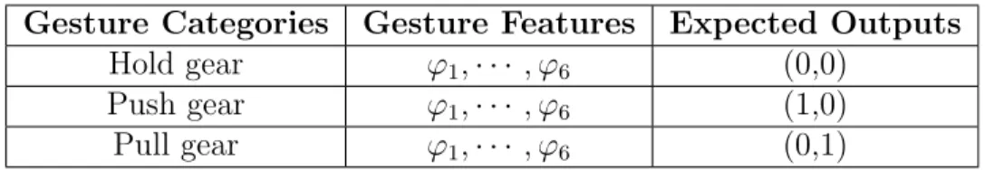
CM AC network is the three gesture types of gear shifting, each allied with
a shifting command for action “Hold gear”, “Push Gear”, or “Pull Gear”. The output layer of CM AC network contains two nodes, and the three gear shifting commands are encoded as (0,0), (1,0), and (0,1).
The training data of theCM AC network is generated by a human demon-strator who repeats each of the three types of gestures 200 times. Thus, there are 600 data instances in the training data set in total. TheCM AC network contains six layers, each of which has five blocks, and the network’s learn-ing rate is set as 0.5. Table 3 summarizes the format of the training data. After the training process, the trained CM AC network receives real-time gesture values from human users, and generates the recognized results which is relayed to the FSM as discussed in the next subsection.
Gesture Categories Gesture Features Expected Outputs
Hold gear ϕ1,· · · , ϕ6 (0,0) Push gear ϕ1,· · · , ϕ6 (1,0) Pull gear ϕ1,· · · , ϕ6 (0,1)
Table 3: The Input and Expected Output Formats of theCM AC Neural Network.
2.4.2. Finite State Machine for Gear Shifting
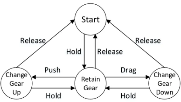
The work flowchart of the FSM applied to retain and change gear states is shown in Figure 5. The FSM consists of a state set and an action set. The state set includes four states: “Start”, “Retain Gear, “Shift Gear Up”,
Start Retain Gear Change Gear Down Change Gear Up Release Release Drag Push Hold Hold Release Hold
Figure 5: The work flowchart of the Finite State Machine.
and “Shift Gear Down”; and the action set includes four actions: “Hold”, “Push”, “Pull”, and “Release”. The actions “Hold”, “Push”, and “Pull” ac-tions correspond to theCM AC network’s output “Hold gear”, “Push gear”, and “Pull gear”, respectively. The “Release” action means the shifting gear movement is completed. The “Hold” action informs the FSM to retain the current gear state. The “Push” action informs the FSM to shift the current gear up. The “Pull” action informs the FSM to shift the current gear down. The range of gear values is set to [−1,3] ∈ N, where 0 indicates the neutral gear, positive values denote forward movement gears, and negative values denote backward gears. When the FSM state is transferred from “Hold gear” to “Push”, the current gear increases by one gear; when the FSM state is transferred from “Hold gear” to “Pull”, the current gear state decreases by one. The entire work procedure is illustrated in the following pseudo-code.
2.4.3. Accelerator Module
An accelerator module is built to use human gestures to control the robot’s moving velocity with regard to each gear state. The input of the accelerator module is the distance between the human user’s left hand and left shoulder denoted as hdistance, which approximates the operation on the
accelerator or the break (as one can only press the accelerator or the break). In particular, the distance hdistance is calculated as:
hdistance =|zlef thand−zlef tshoulder|, (7)
where zlef thand and zlef tshoulder are the left hand and left shoulder positions
in the z direction, respectively.
Both the current gear state and distancehrepresenting the control of ac-celerator or break, are sent to the fuzzy controller module to produce velocity
Algorithm 1 The state transition procedure of FSM.
1: if “Hold gear” gesture is detectedthen
2: The state transits from “Start” to “Retain Gear”
3: if “Push gear” gesture is detected then
4: The state transits from “Retain Gear” to “Shift Gear Up”
5: and the current gear state increases by one
6: if “Hold gear” gesture is detectedthen
7: The state transits to “Retain Gear”
8: else
9: The state transits to “Start”
10: end if
11: else if “Pull gear” gesture is detectedthen
12: The state transits from “Retain Gear” to “Shift Gear Down”
13: and the current gear state decreases by one
14: if “Hold gear” gesture is detectedthen
15: The state transits to “Retain Gear”
16: else
17: The state transits to “Start”
18: end if
19: else
20: The state transits to “Start”
21: end if
22: else
23: Retain the current state
commands. To facilitate this, hdistance has to be converted to discretization
values, which is implemented by:
h= γ·hdistance
|Pneck−Pspine|
+ς, (8)
where, Pneck and Pspine denote the human user’s neck and spine positions,
respectively;γis an amplification factor, empirically set to 10;ς is a constant, empirically set to 1. γ and ς work together to ensure that the range of h
is from 1 to 9. The utilisation of the distance between the neck and spine ensures that the proposed system can be used by users in different sizes, and thus guarantees the wide applicability of the system.
2.4.4. Fuzzy Controller Module
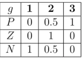
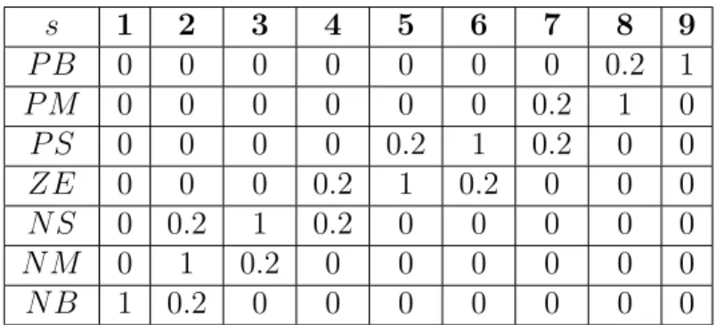
A fuzzy controller is applied in this work to control the velocity of the mobile robot, which takes the current gear state (g) and the distance (h) between the human user’s left hand and left shoulder as inputs, and produces the velocity values (s) of the mobile robot. The fuzzy rule base is created based on domain knowledge. The domains of variables (g, h, s) are discretely defined as: g : [1,2,3] h: [1,2,3,4,5,6,7,8,9] s: [1,2,3,4,5,6,7,8,9]. (9)
These variable domains are further fuzzy partitioned in linguistic values as:
g : [P, Z, N] h: [P B, P S, ZE, N S, N B] s: [P B, P M, P S, ZE, N S, N M, N B]. (10)
The membership functions of these linguistic values regarding fuzzy varialbes
g, h, s are listed in Tables 4, 5, and 6, respectively.
g 1 2 3
P 0 0.5 1
Z 0 1 0
N 1 0.5 0
h 1 2 3 4 5 6 7 8 9 P B 0 0 0 0 0 0 0 0.5 1 P S 0 0 0 0 0 0.5 1 0.5 0 ZE 0 0 0 0.5 1 0.5 0 0 0 N S 0 0.5 1 0.5 0 0 0 0 0 N B 1 0.5 0 0 0 0 0 0 0
Table 5: The membership functions of linguistic values of variableh.
s 1 2 3 4 5 6 7 8 9 P B 0 0 0 0 0 0 0 0.2 1 P M 0 0 0 0 0 0 0.2 1 0 P S 0 0 0 0 0.2 1 0.2 0 0 ZE 0 0 0 0.2 1 0.2 0 0 0 N S 0 0.2 1 0.2 0 0 0 0 0 N M 0 1 0.2 0 0 0 0 0 0 N B 1 0.2 0 0 0 0 0 0 0
Table 6: The membership functions of linguistic values of variables.
The fuzzy rules of the fuzzy controller are summarized in Table 7. The fuzzy controller is implemented using the Mamdani fuzzy inference system [26]. The centroid method is used for the defuzzificaiton calculation, which is
ob-g s h P B P S ZE N S N B P P B P B P M P M P S Z P M P S ZE N S N M N N S N M N M N B N B
Table 7: The fuzzy control rules table.
tained by: s= Pn i=1νiµ(νi) Pn i=1µ(νi) . (11)
where,νidenotes the elements in the output domain;µ(νi) denotes the
mem-bership of element νi; and n denotes the number of activated members (i.e.,
fuzzy controller not only addresses the difficulty of data capturing as the rule base is generated using expert knowledge, but also helps in meeting the requirements of real-tiem control. The output of the fuzzy controller, that is the mobile robot’s velocity,s, is in the range of [0,10]. Notice that the mobile platform uses an internal velocity unit (mm/s), s cannot be directly sent to the mobile platform. Equation 12 is therefore introduced in this work to con-vert the output from the fuzzy controller to the mobile platform’s velocity unit.
vcurrent =s·ψ, (12)
where ψ is a proportionality constant. In this work, ψ is empirically set to 100mm/s.
2.5. Human-robot Interaction Interface
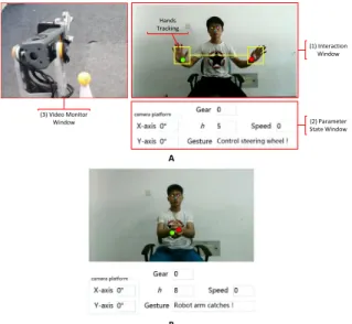
A B (1) Interaction Window (2) Parameter State Window Hands Tracking (3) Video Monitor Window
Figure 6: The human-robot interaction interface. (A) The interface contains a interaction window, a video monitoring window, and a parameter state window. (B) The hand gesture for the manipulator’s capturing commend.
The dashboard of the human-computer interface is shown in Figure 6-A, which consists of three display windows, including the interaction window, the parameter state window, and the video monitor window. The interaction window shows the reflection of the human user gestures, which are captured by the “Kinect 2”. Human users can adjust their gestures by watching the
mirroring images. Several bright spots in the video monitoring window in-forms the human users that the hand gesture classification module is working. In particular, larger green and yellow spots indicate the two wrist skeleton joints. Figure 6-B demonstrates the predefined gesture used for the object-capturing command. When the human users intend to let the mobile robot capture an object, which appears within the robot’s workspace, the human user straightens the arms and holds the hands together in front of the chest. If the mobile robot receives this command, the manipulator module is in-voked to complete an object-capturing movement (refer to [24, 25] for more details on the implementation on the object-capturing ability).
The parameter state window displays five boxes: the camera platform’s position, the current gear state g, the accelerator position h, the robot’s moving velocity s, and the current gesture’s type (Gesture). The Gesture
box shows the current states of human gestures, including: “Move Forward”, “Move Backward”, “Turn Left”, “Turn Right”, “Control Steering Wheel”, “Hold”, and “Push and Pull”. The g box indicates the current gear’s value, which is an integer in the range of [−1,3]∈N, in which 0 is neutral. Positive integer values represent the three gears for moving forward; −1 represents the only reverse gear. The h box indicates the distance between the human user’s left hand and chest, which is in the range of [1,9] ∈ N. The s box shows the output of the fuzzy controller for speed control, and the range of
s is [1,9]∈N.
The video monitoring window simply displays the images of the manipu-lator’s workspace, which are captured by the cameras mounted on the mobile robot. Although the robot’s vision system contains two cameras, only the images captured by the right camera are displayed in the video monitoring window as it generally includes the complete scene for object-capturing tasks.
3. Experimentation and Evaluation
The proposed approach uses human gestures similar to the practical driv-ing gestures, to control a mobile robot. In particular, an adaptive CMAC network is applied to classify human gestures of gear shifting; the recogni-tion of gestures simulate break and accelerator is implemented by a simple distance-based gesture recognition approach; and a specifically designed con-trol procedure is used to recognize the steering gestures and produces concon-trol commend for the mobile robot. Both the identified gear shifting and the ac-celerator/break gestures are fed into a fuzzy controller which produces the
velocity control command for the mobile robot. The complex parts of the system implemented in the experiment, including the training of the CMAC network for gear shifting gesture recognition, the evaluation of the steering control subsystem, and the evaluation of the velocity control subsystem are detailed in subsections 3.2, 3.3 and 3.4, respectively. Note that there is also a hand-eye coordination system is used in this work and thus the experiment to perform object-capturing tasks, but the details of the implementation of this system is omitted as this is beyond the main focus of this paper.
In this phase, enough training data must be collected; then, these training data are used to train the adaptive CMAC network. After the training phase, the steering control and velocity control subsystems are evaluated by our experiments. The following subsections specify the training results of the adaptive CMAC networks, and the evaluations of the steering control and velocity control modules.
3.1. Mobile Robot Hardware
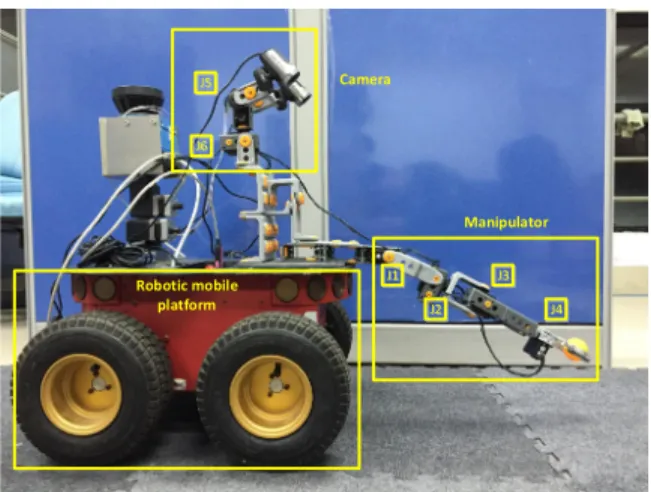
Camera J2 Robotic mobile platform Manipulator J1 J3 J4 J6 J5
Figure 7: The overview of the robot’s hardware system. The robot contains a mobile platform and a robotic hand-eye coordination system.
The hardware of the experimental robot system used in this experiment is shown in Figure 7, which consists of two components: a mobile platform and a robot’s hand-eye coordination system. The mobile platform is a “Pioneer-3AT” robot, which has four wheels and an embedded control system. The robot’s steering mechanism is implemented by changing the velocity differ-ence of the wheels on the two two sides of the mobile platform.
The hand-eye coordination system consists of a binocular camera system and a 5-DOFs manipulator. The manipulator is equipped with four motors
J1, J2, J3, and J4. The former three motors jointly drive a gripper to move in a three-dimensional workspace. The gripper’s opening and closing actions are driven by the J4 motor. The robot’s vision is implemented by a mo-torized binocular vision system with a fixed posture. The mobile platform and robotic hand-eye coordination of this paper is adapted from the work described in [27, 24].
3.2. Training of CMAC for Gear Shifting Gesture Recognition
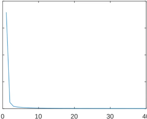
0 10 20 30 40 Training Epoches 0 0.1 0.2 0.3 0.4 Erros
Figure 8: The error convergence curve of theCM AC network for gesture recognition.
The training error curve of theCM AC network over 40 epochs based on 510 training instances is shown in Figure 8. Because of the CMAC’s excellent classification ability, the training error decreases rapidly during the first 10 epochs. At the 20th epochs, the error has already decreased to 0.0011; the training error finally terminates at 6.8438e−04. Extra 90 testing instances are used to evaluate the CM AC’s performance. The total testing error for the 90 instances is 5.6204e−04. The network with such a low error vale can sufficiently support the gear classification.
3.3. Steering Control Subsystem
The steering control module is implemented using the hand positions of human users, which is simple but effective and efficient. Randomly take one
steering control task as an example for the discussion. As shown in Figure 9, which is a screenshot of the human-robot interaction interface window, the two larger green and red points indicate the positions of the human user’s left and right hands respectively, and the recognized gesture is indicated in the “Gesture” box. At the top-left figure, both hands are at the same horizontal position; and accordingly, the Gesture box displays “Move Forward” which represents the correct interpretation of the gesture and thus the success of the subsystem. In this situation, no steering information is sent to the robot. At the top-right corner of the figure, the position of the right hand is higher than that of the left hand; therefore, the Gesture box successfully shows “Turn Right”. In the bottom picture, the position of the left hand is higher than that of the right hand; therefore, the Gesture box correctly indicates “Turn Left”.
A. No turning B. Turn right
C. Turn left
Move Forward
Figure 9: The testing results of the steering gestures. Picture A illustrates the “Move Forward” gesture; Picture B shows the “Turn Right” gesture; and Picture C indicates the “Turn Left” gesture.
3.4. Velocity Control Subsystem
The robot’s velocity is determined by the the current gear state,g, and the accelerator’s position, h, using a fuzzy control algorithm. Therefore, in this section, the performances of the accelerator and gear control are evaluated
first, followed by the evaluation of the performance of the overall velocity control.
3.4.1. Accelerator Module
Figure 10 shows one random case of the accelerator/break control, in-cluding two human gestures representing the fastest and slowest accelerator positions. The top-left picture demonstrates the distance between the user’s hands and chest, because the hands are very close to the chest, that is h is 1. If the current gear state, g is 2, the output, s, of the fuzzy controller is then 3. The top-right picture illustrates the human-robot interaction inter-face window. The bottom-left picture shows the largest distance between the user’s hands and chest, and thus, h is 9. If the current gear state, g, is 2, the output s of the fuzzy controller is 7. This case clearly demonstrates the working the proposed accelerator module.
g = 2, h = 1, s = 3 g = 2, h = 9, s = 7 h h A. Low speed B. High speed Move Forward Move Forward
Figure 10: Demonstration of the experimental results of the accelerator control. The first row shows the gesture of low speed and the second row shows the gesture of high speed.
3.4.2. Gear Control Module
The gear control module integrates the CM AC neural network and the finite state machine. The performance of the CM AC has been discussed in Section 3.2; therefore, this section only evaluates the final recognized results
Pull
Figure 11: Demonstration of the experimental results of the gear control gestures.
of the sampled gestures. Figure 11 shows the experimental results of the gear control function. The figure shows three gestures, which relate to the three gear operation commands. The top picture shows the “Hold” command, the bottom-left shows the “Push” command, and the bottom-right shows the “Pull” command. The human’s right arm is highlighted by a yellow box.
The human’s right arm is horizontal and the hand faces downwards shown in the top picture of Figure 11,. This gesture informs the FSM to retain the current gear. For example, if the current gear state is 0, the FSM will retain this gear state. In the bottom-left of the picture, the human’s right arm is straight and the hand is close to the human’s leg. This gesture informs the FSM to change the state from “Retain the Gear” to “Shift Gear Up”. For example, if the current gear state is 0, the gear state will be increased to 1. The right arm in the bottom-right picture is bent upwards. This gesture informs the FSM to change the state from “Retain the Gear” to “Shift Gear Down”. For example, if the current gear state is 0, the gear state will be decreased to −1, which directs the robot to reverse back. The case discussed herein as shown in Figure 11 shows that the FSM andCM AC work together successfully supporting the gear shifting function for the mobile robot.
3.4.3. The Overall Velocity Control
Figure 12 shows the output of the fuzzy controller with different inputs. The three curves indicate the velocities with the three gear states against the
accelerator’s values. The velocity curve of Gear 1 is presented as the solid line in the figure. The highest and lowest velocities of Gear 1 are 3 and 1, respectively. The velocity curve of Gear 2 is presented as a dot-dash line. The highest and lowest velocities of Gear 2 are 6 and 3, respectively. The velocity curve of Gear 3 is presented as a dash line, and the velocity increases from 7 to 9 in this line.
0 1 2 3 4 5 6 7 8 9 10 0 1 2 3 4 5 6 7 8 9 10 Hand Distance d Speed Gear 3 Gear 2 Gear 1
Figure 12: The result of the robot’s velocity generated by the fuzzy controller. The three curves indicate the velocities with regard to the three gear states against the accelerator’s values.
3.5. The Overall Manoeuvring
The overall manoeuvring performance (combining the velocity control and steering control modules) of the mobile robot is shown in Figure 13. The first two pictures show the robot’s moving trajectories with different velocities. The third picture shows the robot’s trajectories when turns were implied. These pictures were taken by the multiple exposure mode of the camera, which captured the moving object’s images and integrated the cap-tured images into one picture. Denser images of the moving object in such a picture indicate slower moving velocity. Therefore, the moving velocity in the first picture is slower than that in the second. The result of the different number of images included in the pictures taken in a fixed time span proves the previous velocity setup, in which s takes 2 for the first picture and s
takes 4 for the second one.
The third row of Figure 13 shows a complete procedure where the mobile robot avoids an obstacle and moves towards a target object. This picture was also taken by the multiple exposure mode. The obstacle was an orange
wood brick, and the target was a yellow ping-pong ball. In this experiment, the human successfully controlled the robot to turn right to avoid obstacle using hand gestures, and then turn left to reach the target. The moving time of the test was around ten seconds. The moving trajectory proves that the mobile robot is able to perform prompt turning actions.
Speed = 2
Speed = 4
Turning
Figure 13: Demonstration of the result of the vehicle’s turning. The first two rows of pictures show the robot’s moving trajectories with different velocities. The first row of picture contains 10 images of the moving robot, and the second row of picture contains 6 images of the moving robot. The third row of picture shows the robot’s turning trajectories.
3.6. Discussions and Comparisons
The proposed approach has demonstrated its effectiveness in controlling the mobile robot to reach target objects for object-capturing tasks through the experiments. This approach differs from the existing work in that the proposed mobile robot uses natural human gestures similar to a human’s actual driving gestures. The complex gesture recognition tasks have been implemented by employing a CMAC neural network with successful experi-mental results generated. To further evaluate the strengths of this research, a
comparison of the proposed system with the typical mobile robot approaches is summarized in Table 8. In particular, the comparison is made from three important aspects: 1) human-robot interaction command type, 2) velocity control of mobile robot, and 3) control system’s implementation.
First, many existing approaches [15, 17, 18, 19] prefer to apply qualitative commands to control mobile robots. These qualitative commands directly inform robots to move forwards or backwards, and turn left or right. How-ever, the propose approach herein applies quantitative commands to control the robot, using detailed steering and velocity values to control the robot. Thanks to this, the proposed mobile robot in this work produces smooth movement trajectories and delivers fast response of commands. Second, few existing conventional approaches support multiple velocities for mobile robots. In contrast, the proposed work applies practical driving gestures for normal vehicles to control the mobile robot. Thus, the robot’s velocities are determined by the current gear state and accelerator state. Consequently, the users can conveniently and flexibly control the velocity and direction of the mobile robot. Third, the proposed approach adopts the CMAC network and a fuzzy controller to implement the overall velocity control, which benefits both the self-adaption and learning abilities of the CMAC, and the running efficiency of fuzzy inference systems in implementing real-time control. As a result, the proposed system is able to generate new gesture commands, if required, by sampling new human gestures. In contrast, in order to inte-grate new commands, other robot systems usually require extra design and development stage of complex mathematical modelling [3, 4, 1, 28].
4. Conclusion
This paper presented an approach which uses human gestures to control a mobile robot with a manipulator for object-capturing tasks. In particular, the most complex part of the method, that is the quantitative velocity control is achieved by applying an adaptive CMAC network, a finite state machine, and a fuzzy controller. The experiments demonstrate that human users can successfully control the mobile robot to move it at various speeds to avoid obstacles and reach the target objects. These experiments also illustrate the key advantage of this research over the existing work in that the proposed approach greatly simplifies the complexity of mobile robot control. Therefore, the proposed approach improves the robot’s autonomous and collaborative
Options: Existing Meth-ods: The Proposed Method: Human-robot in-teraction command type Qualitative commands e.g. [15, 17, 18, 19] Quantitatively com-mands, such as steering degrees and velocity values; Velocity control of
mobile robot
Few methods di-rectly support
Velocity is defined by the gear chang-ing and accelerator modules; Implementation of control system Implemented by mathematical mod-elling methods [3, 4, 1, 28] A learning ability is established in this method, so as to handle new gesture commands.
Table 8: The comparison table
working ability to perform in complex environments which greatly widen the applicability of the mobile robots.
The proposed system can be improved in multiple ways. Firstly, more natural body information, such as EMG or EEG signals, can be used as the robot system’s input to control mobile robots [29, 30, 31]. Also, in the present work, only static cameras are used for the robotic vision. This can be enhanced by applying a motorized binocular vision system, which will enable the mobile robot to detect targets in a much larger working area. In addition, the current gesture recognition system cannot handle the occlusion problem. Thus it is desirable to integrate the occlusion elimination algorithms into the system.
Acknowledgement
The authors are very grateful to the anonymous reviewers for their con-structive comments that have helped significantly in revising this work. This work was supported by the Major State Basic Research Development Pro-gram of China (973 ProPro-gram) (No. 2013CB329502), the Fundamental Re-search Funds for the Central Universities (No. 20720160126), the National Natural Science Foundation of China (No. 61673322, 61673326, and 91746103),
and Natural Science Foundation of Fujian Province of China (No. 2017J01128 and 2017J01129).
[1] Y. Jia, N. Xi, Y. Cheng, S. Liang, Coordinated motion control of a nonholonomic mobile manipulator for accurate motion tracking, in: 2014 IEEE/RSJ International Conference on Intelligent Robots and Systems (IROS 2014), 2014, pp. 1635–1640. doi:10.1109/IROS.2014.6942774. [2] M. Boukens, A. Boukabou, Design of an intelligent optimal neural
network-based tracking controller for nonholonomic mobile robot systems, Neurocomputing 226 (Supplement C) (2017) 46 – 57. doi:https://doi.org/10.1016/j.neucom.2016.11.029.
URLhttp://www.sciencedirect.com/science/article/pii/S0925231216314308
[3] L. Wang, L. Zhang, L. Guo, J. Li, X. Wen, J. Yi, A system of robot mo-bile manipulation based on teleoperation with human motion capture, in: 2015 IEEE International Conference on Information and Automa-tion, 2015, pp. 1503–1508. doi:10.1109/ICInfA.2015.7279523.
[4] P. Zhang, G. Du, B. Liang, X. Wang, Human-manipulator interface using hybrid sensors via CMAC for dual robot, International Journal of Computers Communications and Control 10 (2) (2015) 280–290.
[5] D. Huang, J. Zhai, W. Ai, S. Fei, Disturbance observer-based robust control for trajectory tracking of wheeled mobile robots, Neurocomputing 198 (Supplement C) (2016) 74 – 79, advances in Neural Networks, Intelligent Control and Information Processing. doi:https://doi.org/10.1016/j.neucom.2015.11.099.
URLhttp://www.sciencedirect.com/science/article/pii/S0925231216003179
[6] J. Wu, G. Qiao, J. Zhang, Y. Zhang, G. Song, Hand motion-based remote control interface with vibrotactile feedback for home robots, In-ternational Journal of Advanced Robotic Systems 10 (270).
[7] N.-B. Hoang, H.-J. Kang, Neural network-based adaptive track-ing control of mobile robots in the presence of wheel slip and external disturbance force, Neurocomputing 188 (2016) 12 – 22. doi:http://dx.doi.org/10.1016/j.neucom.2015.02.101.
[8] A. Billard, S. Calinon, R. Dillmann, S. Schaal, Survey: Robot Program-ming by Demonstration, in: Handbook of Robotics, Vol. chapter 59, MIT Press, 2008.
[9] E. Ohn-Bar, M. M. Trivedi, Hand gesture recognition in real time for automotive interfaces: A multimodal vision-based approach and evalu-ations, IEEE Transactions on Intelligent Transportation Systems 15 (6) (2014) 2368–2377. doi:10.1109/TITS.2014.2337331.
[10] G. Gioioso, G. Salvietti, M. Malvezzi, D. Prattichizzo, Mapping syner-gies from human to robotic hands with dissimilar kinematics: An ap-proach in the object domain, IEEE Transactions on Robotics 29 (4) (2013) 825–837. doi:10.1109/TRO.2013.2252251.
[11] R. Dillmann, T. Asfour, M. Do, R. J¨akel, A. Kasper, P. Azad, A. Ude, S. Schmidt-Rohr, M. L¨osch, Advances in robot programming by demonstration, KI - K¨unstliche Intelligenz 24 (4) (2010) 295–303. doi:10.1007/s13218-010-0060-0.
URL http://dx.doi.org/10.1007/s13218-010-0060-0
[12] H. Zeng, Y. Huang, F. Chao, C. Zhou, Survey of robotic calligraphy research, CAAI Transactions on Intelligent Systems 11 (1) (2016) 15– 26.
[13] F. Chao, Y. Huang, X. Zhang, C. Shang, L. Yang, C. Zhou, H. Hu, C.-M. Lin, A robot calligraphy system: From simple to complex writing by human gestures, Engineering Applications of Artificial Intelligence 59 (2017) 1–14. doi:http://dx.doi.org/10.1016/j.engappai.2016.12.006.
URLhttp://www.sciencedirect.com/science/article/pii/S0952197616302329
[14] Y. Xu, C. Yang, J. Zhong, N. Wang, L. Zhao, Robot teaching by teleoperation based on visual interaction and extreme learning machine, Neurocomputingdoi:https://doi.org/10.1016/j.neucom.2017.10.034.
URLhttp://www.sciencedirect.com/science/article/pii/S0925231217316855
[15] M. R. Pedersen, V. Kr¨uger, Gesture-based extraction of robot skill parameters for intuitive robot programming, Journal of Intelligent & Robotic Systems 80 (1) (2015) 149–163. doi:10.1007/s10846-015-0219-x.
[16] S.-G. Pentiuc, O. M. Vultur, A. Ciupu, Intelligent Distributed Comput-ing VII: ProceedComput-ings of the 7th International Symposium on Intelligent Distributed Computing - IDC 2013, Prague, Czech Republic, September 2013, Springer International Publishing, 2014, Ch. Control of a Mobile Robot by Human Gestures, pp. 217–222.
[17] M. Wongphati, H. Osawa, M. Imai, Gestures for manually controlling a helping hand robot, International Journal of Social Robotics 7 (5) (2015) 731–742. doi:10.1007/s12369-015-0302-2.
URL http://dx.doi.org/10.1007/s12369-015-0302-2
[18] M. Wongphati, H. Osawa, M. Imai, User-defined gestures for controlling primitive motions of an end effector, Advanced Robotics 29 (4) (2015) 225–238. arXiv:http://dx.doi.org/10.1080/01691864.2014.978371, doi:10.1080/01691864.2014.978371.
URL http://dx.doi.org/10.1080/01691864.2014.978371
[19] B. Burger, I. Ferran´e, F. Lerasle, G. Infantes, Two-handed gesture recog-nition and fusion with speech to command a robot, Autonomous Robots 32 (2) (2012) 129–147. doi:10.1007/s10514-011-9263-y.
URL http://dx.doi.org/10.1007/s10514-011-9263-y
[20] N. Yu, C. Xu, K. Wang, Z. Yang, J. Liu, Gesture-based telema-nipulation of a humanoid robot for home service tasks, in: 2015 IEEE International Conference on Cyber Technology in Automation, Control, and Intelligent Systems (CYBER), 2015, pp. 1923–1927. doi:10.1109/CYBER.2015.7288241.
[21] H.-Y. Lin, C.-F. Wu, C.-J. Lin, C.-Y. Yu, A fuzzy cerebellar model ar-ticulation controller using a strategy-adaptation-based bacterial forag-ing optimization algorithm for classification applications, International Journal of Fuzzy Systems 17 (2) (2015) 303–308.
[22] T.-K. Kang, H. Zhang, G.-T. Park, D. W. Kim, Ego-motion-compensated object recognition using Type-2 fuzzy set for a moving robot, Neurocomputing 120 (2013) 130 – 140, image Feature Detection and Description. doi:http://dx.doi.org/10.1016/j.neucom.2012.09.041.
[23] F. Bocklisch, S. F. Bocklisch, M. Beggiato, J. F. Krems, Adap-tive fuzzy pattern classification for the online detection of driver lane change intention, Neurocomputing 262 (Supplement C) (2017) 148 – 158, online Real-Time Learning Strategies for Data Streams. doi:https://doi.org/10.1016/j.neucom.2017.02.089.
URLhttp://www.sciencedirect.com/science/article/pii/S0925231217309797
[24] C.-H. Chen, C.-C. Chung, F. Chao, C.-M. Lin, I. J. Rudas, Intelligent robust control for uncertain nonlinear multivariable systems using re-current cerebellar model neural networks, Acta Polytechnica Hungarica 12 (5) (2015) 7–33.
[25] F. Chao, Z. Zhu, C. M. Lin, H. Hu, L. Yang, C. Shang, C. Zhou, En-hanced robotic hand-eye coordination inspired from human-like behav-ioral patterns, IEEE Transactions on Cognitive and Developmental Sys-tems Accepted. doi:10.1109/TCDS.2016.2620156.
[26] F. Camastra, A. Ciaramella, V. Giovannelli, M. Lener, V. Rastelli, A. Staiano, G. Staiano, A. Starace, A fuzzy decision system for ge-netically modified plant environmental risk assessment using mamdani inference, Expert Systems with Applications 42 (3) (2015) 1710 – 1716. doi:https://doi.org/10.1016/j.eswa.2014.09.041.
URLhttp://www.sciencedirect.com/science/article/pii/S0957417414005946
[27] D. Zhou, F. Chao, Z. Zhu, C. M. Lin, C. Zhou, A novel approach to a mobile robot via multiple human body postures, in: 2016 12th World Congress on Intelligent Control and Automation (WCICA), 2016, pp. 1463–1468. doi:10.1109/WCICA.2016.7578290.
[28] Y. Jia, Y. Liu, N. Xi, H. Wang, P. St¨urmer, Design of robotic human assistance systems using a mobile manipulator, International Journal of Advanced Robotic Systems 9 (165). doi:10.5772/50828.
[29] Z. Ju, H. Liu, Human hand motion analysis with multisensory informa-tion, IEEE/ASME Transactions on Mechatronics 19 (2) (2014) 456–466. doi:10.1109/TMECH.2013.2240312.
[30] Y. J. Kim, H. S. Lee, S. Jung, Line tracking control of a mobile robot using emg signals from human hand gestures, in: 2015 12th International
Conference on Ubiquitous Robots and Ambient Intelligence (URAI), 2015, pp. 354–354. doi:10.1109/URAI.2015.7358976.
[31] E. Hortal, D. Planelles, A. Costa, E. Iez, A. beda, J. Azorn, E. Fern-ndez, Svm-based brainmachine interface for controlling a robot arm through four mental tasks, Neurocomputing 151, Part 1 (2015) 116–121. doi:http://dx.doi.org/10.1016/j.neucom.2014.09.078.