MASTER THESIS
TITLE: Research on path establishment methods performance in SDN-based networks
MASTER DEGREE: Master of Science in Telecommunication Engineering & Management
AUTHOR: David José Quiroz Martiña
DIRECTOR: Cristina Cervelló-Pastor
TITLE: Investigación en el rendimiento de métodos de establecimiento de rutas en redes basadas en SDN.
MASTER DEGREE: Master of Science in Telecommunication Engineering & Management
AUTHOR: David José Quiroz Martiña
DIRECTOR: Cristina Cervelló-Pastor
DATE: 16 de Noviembre del 2015
Overview
Este proyecto tiene como objetivo la evaluación de métodos seleccionados de establecimiento de rutas adaptados a SDN. Se han realizado varios estudios y experimentaciones incluyendo la instalación de un escenario de pruebas de Segment Routing y Proactive Forwarding, la observación de su interoperabilidad con el protocolo OpenFlow, su comportamiento en el manejo del tráfico, su desempeño frente a eventos de la red, y sus efectos sobre el tiempo de respuesta del controlador SDN. El objetivo principal es la investigación sobre la influencia de los métodos de establecimiento de rutas hacia el rendimiento del controlador SDN, que pueden o no, tener un efecto sobre la capacidad de mantener el tráfico durante los cambios controlados e inesperados en la red.
TITLE: Research on path establishment methods performance in SDN-based networks
MASTER DEGREE: Master of Science in Telecommunication Engineering & Management
AUTHOR: David José Quiroz Martiña
DIRECTOR: Cristina Cervelló-Pastor
DATE: November, 16th 2015
Overview
This project aims for the assessment of selected path establishment methods adapted to SDN. Several studies and experimentations are performed including the installation of a Segment Routing and Proactive Forwarding test scenario, the observation of their interoperability with the OpenFlow protocol, their behavior in traffic handling, their performance in front of network events, and their effects on the SDN controller’s time response. The main goal is to research about the influence of path establishment methods towards the SDN controller performance, which may or may not have an effect over the ability to sustain traffic during controlled and unexpected changes in the network.
INTRODUCTION ... 1
CHAPTER 1. SOFTWARE DEFINED NETWORKING AND OPENFLOW ... 3
1.1 Software Defined Networking (SDN) ... 3
1.1.1 Application layer ... 4 1.1.2 Control layer ... 4 1.1.3 Infrastructure layer ... 4 1.2 OpenFlow ... 5 1.2.1 Flow tables ... 6 1.2.2 Group tables ... 8 1.2.3 Meter tables ... 10 1.2.4 OpenFlow channel ... 10 1.2.5 OpenFlow switch ... 12 1.2.6 Openflow versions ... 14
CHAPTER 2. PATH ESTABLISHMENT METHODS ... 15
2.1 Routing fundamentals ... 15
2.1.1 Shortest path routing ... 15
2.1.2 Multipath routing ... 15
2.1.3 Source routing ... 16
2.2 Network performance standards ... 16
2.3 Proactive Forwarding (PF) ... 18
2.4 Multiprotocol Label Switching (MPLS) ... 20
2.4.1 MPLS architecture ... 20
2.4.2 MPLS topology ... 21
2.5 Segment Routing (SR) ... 22
2.5.1 Segment list ... 23
2.5.2 Segment types ... 24
2.5.3 Path computation algorithms ... 25
CHAPTER 3. TEST TOPOLOGY SETUP ... 26
3.1 Control layer involved elements ... 27
3.1.1 SDN controller selection ... 27
3.1.2 Controller’s hardware ... 29
3.1.3 Controller’s software ... 29
3.2 Infrastructure layer involved elements ... 30
3.2.1 Software selection ... 30
3.3 Proactive Forwarding Setup ... 33
3.4 Segment Routing Setup ... 33
3.5 Measurement tools ... 34
3.5.1 iPerf ... 34
3.5.2 Multi-Generator (MGEN) ... 35
3.5.3 Wireshark ... 35
CHAPTER 4. OPERATION IN ONOS CONTROLLERS ... 36
4.1 ONOS architecture ... 36
4.1.1 ONOS subsystems ... 37
4.2 Intent forwarding subsystem ... 38
4.2.1 Intent subsystem ... 38
4.2.2 Topology subsystem ... 39
4.2.3 Intent forwarding operation ... 41
4.3 Segment Routing subsystem ... 42
4.3.1 Path computation ... 43
4.3.2 Group handling ... 43
4.3.3 Segment Routing operation ... 45
4.4 OpenFlow pipeline utilization ... 46
4.4.1 Intent Forwarding pipeline ... 46
4.4.2 Segment Routing pipeline ... 47
CHAPTER 5. EXPERIMENTATION AND RESULTS ... 48
5.1 Experimentation process ... 48
5.1.1 Network performance measurement ... 49
5.1.2 Response time measurement in front of network events ... 49
5.1.3 Static path installation time ... 51
5.1.4 Switch packet forwarding delay measurement... 52
5.1.5 Balanced path load scenario ... 52
5.2 Measurement results ... 53
5.2.1 Test topology traffic performance ... 53
5.2.2 Response to network events ... 53
5.2.3 Response to static path installation ... 54
5.2.4 Switch packet forwarding delay ... 55
5.2.5 Response to network events with balanced path load ... 55
5.3 Results observations ... 56
5.3.1 Packet switching ... 57
5.3.2 OpenFlow messaging and method’s operation influence ... 57
Future work ... 62
REFERENCES ... 64
ACRONYMS ... 67
APPENDIX A: OPENFLOW PIPELINE PROCESSING ... 69
APPENDIX B: NETWORK TOPOLOGY SCRIPTS ... 71
APPENDIX C: ONOS INTENT FRAMEWORK ... 77
APPENDIX D: SR SUBSYSTEM COMPONENTS ... 78
I. Segment Routing Application ... 78
II. Configuration Manager ... 79
III. Segment Routing Driver ... 79
OF 1.3 Group Handler ... 80
Group Recovery Handler ... 80
OF Message Pusher ... 81
Driver API ... 81
APPENDIX E: SOFTWARE INSTALLATION ... 82
I. ONOS Blackbird installation ... 82
Oracle Java 8 JDK installation ... 82
Apache Karaf 3.0.2 and Maven 3.2.3 installation ... 82
Blackbird download and building ... 83
II. ONOS SPRING-OPEN installation ... 88
CLI installation ... 89
III. Mininet installation ... 89
IV. CPqD switch installation ... 90
APPENDIX F: OPERATION EXAMPLES ... 92
I. Controller initialization ... 92
OpenFlow messages ... 92
Flow tables (using a 2 host and 3 routers topology) ... 92
II. Link behavior on Segment Routing ... 94
Multipath links ... 95
Link failures ... 95
III. Label sequencing and forwarding operation ... 97
APPENDIX G: STATISTIC PROCEDURE ... 99
I. Average and standard deviation ... 99
II. Confidence Interval (CI) ... 99
I. Steady state conditions ... 102
II. Switch packet forwarding ... 108
III. Static path installation ... 113
IV. Network events ... 119
V. Balanced path load ... 133
APPENDIX I: JITEL 2015 ARTICLE ... 139
TABLE OF FIGURES
Figure 1.1 - Software Defined Networking Architecture ... 3Figure 1.2 - OpenFlow Architecture ... 5
Figure 1.3 - OpenFlow Table ... 6
Figure 1.4 - OpenFlow version 1.3 flow table ... 8
Figure 1.5 - OpenFlow group table ... 9
Figure 1.6 - OpenFlow meter table ... 10
Figure 1.7 - Components of an OpenFlow switch ... 13
Figure 1.8 - OpenFlow pipeline ... 13
Figure 2.1 - Proactive forwarding model ... 19
Figure 2.2 - MPLS architecture ... 20
Figure 2.3 - MPLS model ... 21
Figure 3.1 - General test network topology ... 26
Figure 3.2 - Proactive Forwarding test topology ... 33
Figure 3.3 - Segment Routing test topology ... 33
Figure 4.1 - ONOS architecture ... 36
Figure 4.2 - ONOS subsystem structure ... 37
Figure 4.3 – Intent compilation process within the subsystem ... 39
Figure 4.4 - Topology subsystem ... 40
Figure 4.5 - Segment Routing subsystem ... 42
Figure 4.6 - Proactive forwarding pipeline utilization ... 47
Figure 4.7 - Segment Routing pipeline utilization ... 47
Figure 5.1 - Traffic generators and Wireshark probes location ... 48
Figure 5.2 – Controller’s response time frame ... 50
Figure 5.3 - Segment Routing processing time frame ... 50
Figure 5.4 - Segment Routing path installation time frame ... 51
Figure 5.5 - Proactive Forwarding path load topology ... 52
Figure 5.6 - Counters summary CLI output ... 55
Figure 5.7 - Test results comparison ... 57
Figure 5.8 - OpenFlow messaging ... 58
Figure 5.9 - Flows allocation during static path configuration ... 59
Figure 5.10 - Path establishment after failures ... 60
Table 1.1 - OpenFlow message description ... 12
Table 1.2 - OpenFlow versions support description ... 14
Table 2.1 - Network performance parameters ... 18
Table 3.1 - SDN controller selection criteria ... 28
Table 3.2 - ONOS software requirements ... 29
Table 3.3 - Infrastructure layer compatibility ... 31
Table 5.1 - Test topology traffic performance ... 53
Table 5.2 - Network event performance ... 54
Table 5.3 - Static path installation response ... 54
INTRODUCTION
Software Defined Networking (SDN) has acquired great acceptance in the networking community. Thus, several developments and advances have been made to introduce new functions and applications that can give more maturity and specialized operations to the system. Some developments include the adaptation of layer 3 (L3) protocols, such as IGP and BGP to support routing methods into the SDN environment. Since the principle of SDN is a centralized control of the network, every operation triggered by these protocols implies processing introduced to the controller and a response time, that may or may not have an impact over the network.
Keeping track of the performance during the adaptation of a new path method to SDN, can help developers setting up a margin, to fulfill a balance between the times required to address the processing needs of the path method, and maintaining a lower response time from the controller.
The main objective of this research is to conduct a conceptual analysis of path establishment methods that may have a practical application over SDN. It is intended to observe in which manner the working principle of path establishment methods can influence the performance of an SDN controller in terms of time response. For this reason, it was decided to make a comparative study of two path establishment methods: The method to observe (Segment Routing), and a reference method currently used in SDN (Proactive Forwarding).
One example of a L3 path establishment method that is being adapted to SDN is Segment Routing. This method constructs an end to end path based on a sequence of nodes and port codes called segments. On the first node, a packet is guided by this sequence of segments. Once the packet passes through each segment, its related segment id (SID) is pulled out of the sequence. This behavior is maintained until the packet arrives to the edge node that connects to the destination.
This research conducts a series of measurements that helps to determine the approximated response time that Segment Routing can introduce into an SDN controller during normal operations and during network events. The response times are compared with the performance of the Proactive Forwarding method. This mechanism is a L2 path establishment procedure, traditionally used in SDN to construct paths according to traffic destination addresses, and set up by flows installed on all switches relevant to the path. The response times of this method are used as a reference to visualize any additional time response introduced by Segment Routing, with respect of the controller’s default state where Proactive Forwarding is supported.
The second objective of the investigation is to observe the interaction of the path establishment methods with OpenFlow. Both path methods are established by the controller using the OpenFlow protocol as their interface between the control plane and data plane. The actions triggered by both methods are exchanged between the controller and the network devices through OpenFlow messages.
OpenFlow has been the first protocol used in SDN as the communication interface between the control plane and the forwarding plane, found in network devices such as switches and routers. It is widely used in most of the current SDN controllers to address the dynamic control of network resources according to the needs of today's applications. It uses TCP sessions to carry out instructions given by the SDN controller, and programs the flow tables found in different network devices, to set an OpenFlow pipeline where the forwarding process is carried out by entries found in the flow tables.
This research will show that, according to the method applied, the actions triggered by both path methods will determine the way of how the OpenFlow pipeline will be used on the network devices during packet forwarding.
The remainder of this work is organized as follows:
Chapter 1 describes the fundamental concepts of SDN and OpenFlow, with more specific information on the second one, to give the reader a wider view about the operation of OpenFlow.
Chapter 2 describes the fundamental concepts of routing, types of routing, the path establishment methods to study, and the parameters to observe performance and routing metrics.
Chapter 3 describes the network scenario, including the test scenarios and the involved elements specifications, in which comparison between several options were made.
Chapter 4 describes the specific operation of Proactive Forwarding and Segment Routing on the selected SDN controller, in which its architecture is explained.
Chapter5 describes the experimentation process, the results obtained, and the observations gathered from both methods.
Finally, the conclusions of the research will be given, plus some future work that may follows from this research.
CHAPTER 1. SOFTWARE DEFINED NETWORKING
AND OPENFLOW
Software Defined Networking (SDN) is a solution that departs from the idea of giving a centralized view and management of the network infrastructure, being capable of making traffic decisions depending on the need of applications and services. In order to manage the various network devices to react according to traffic behaviors, a set of protocols were developed to standardize an interface between the centralized element and the network devices. This chapter gives the necessary fundamentals on SDN and OpenFlow architectures to comprehend the later experimentation performed in this research.
1.1 Software Defined Networking (SDN)
This technology basically separates the control plane from the data plane of each network equipment (Fig. 1.1), centralizing the network intelligence that handles traffic control, switching, routing, and Quality of Service (QoS) to achieve a more efficient control of the network. To comply with Service Level Agreements (SLA), each application communicates with the control plane through API (Application Programming Interface) interconnections in order for the control plane to execute decisions of package forwarding, traffic handling, and QoS policies that better suits the service requirements in real time.
Figure 1.1 - Software Defined Networking Architecture1
1.1.1 Application layer
The application layer represents network applications that interact with the control layer to communicate their requirements for network resources and exercise specific changes in the network, achieving the desired network behavior and QoS for a certain traffic. The application layer communicates with the control layer using application interfaces like North Bound Interface (NBI) or Java API to carry out synchronous and asynchronous messages. They can provide a wide flexibility since different types of traffic can be handled by different network applications separately, using the network infrastructure as a shared resource. For example, network control traffic like LLDP (Link Layer Data Protocol) messages, are treated by a separate network application than normal data traffic like ICMP (Internet Control Message Protocol) messages. The path establishment methods that would be seen in this document, are network applications functioning at this layer.
1.1.2 Control layer
The control layer, also known as the Network Operating System (NOS) or SDN controller, is an intermediary between the infrastructure layer and the application layer. It gives applications an abstraction of the network topology, an inventory of the features supported by each network device, network statistics, host tracking information, and packet information. Applications can make decisions accordingly, then the control layer translate those decisions into instructions downloaded to the infrastructure layer, and execute the appropriate network settings for the current traffic.
The control layer is conceived to be logically centralized, that means, that the NOS can operate under a cluster of physical servers to share the workload of the system.
1.1.3 Infrastructure layer
The infrastructure layer comprises the data plane of the SDN architecture, represented by forwarding devices like switches and routers. They forward packets according to the instructions received by the control layer, like dropping a packet or sending it out through an output interface. The forwarding devices maintains communications with the control layer to keep the system updated on their network status like active ports, adjacent neighbors, supported features, counters information, and event notifications.
Logically, the forwarding devices are viewed as a Datapath and identified by a Datapath ID (DPID). This information is used by the SDN controller to address specific instructions to certain devices, like forwarding actions, or to identify each of the network devices in the topology abstraction.
The communication channel between the infrastructure layer and control layer is referred as the SouthBound Interface, which is characterized by several
communication protocols that carry out the interaction between the SDN controller and the Datapaths. The most common SouthBound protocol used is OpenFlow, being accepted by most vendors since it’s been in constant development to work for SouthBound communications and network control.
1.2 OpenFlow
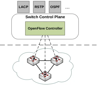
OpenFlow is a set of protocols and an API that is used in SDN to address the separation of the control plane and data plane, using a standardized protocol between the SDN controller and the network devices for SouthBound communication, forwarding instantiation, and provisioning network programmability from a centralized view via an extensible API. As the communication interface between the control layer and infrastructure layer, it is widely used in most of the current SDN controllers to address the dynamic control of network resources according to the needs of today's traffic. Fig. 1.2, displays the key components of the OpenFlow model:
Switch Control Plane OpenFlow Controller
LACP RSTP OSPF
...
OpenFlow Protocol
Figure 1.2 - OpenFlow Architecture2
From the control plane, the OpenFlow API delivers network programmability in which a set of instructions are prepared to perform a forwarding abstraction, using the flow tables of the network elements, and making possible to handle the traffic according to the computation of network applications. Then the OpenFlow protocol establishes a TCP based communication between the control plane and data plane to carry out the OpenFlow messages to the network elements.
The OpenFlow protocol is divided in two parts: wire protocol and configuration and management protocol. The wire protocol is the most referenced during the experimentation of this project, and is responsible for establishing control sessions, defining message structures for exchanging flow modifications, collecting statistics, and defining the fundamental function of a switch (ports and tables) [2]. On the other hand, the configuration and management protocol (of-config protocol) allocates physical ports to a controller, and define high availability and actions on controller connection failure [2].
1.2.1 Flow tables
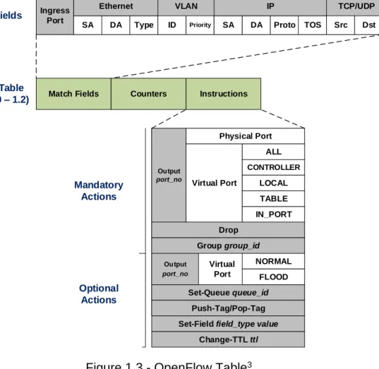
A flow table is a data structure that resides in the data plane of an OpenFlow switch, and is essential to perform matching operations on packets that are being treated by the forwarding device. The common structure of the flow table is presented on Fig. 1.3.
Ingress Port
SA DA Type ID Priority SA DA Proto TOS Src Dst
Ethernet VLAN IP TCP/UDP
Match Fields Counters Instructions
Output port_no Physical Port Virtual Port IN_PORT ALL CONTROLLER LOCAL TABLE Drop Set-Queue queue_id Push-Tag/Pop-Tag NORMAL FLOOD Output port_no Virtual Port Match Fields Flow Table (OF 1.0 – 1.2) Mandatory Actions Optional Actions Group group_id
Set-Field field_type value
Change-TTL ttl
Figure 1.3 - OpenFlow Table3
The match fields of the packets are based on the TCP/IP model, each header field can contain information including physical interfaces, MAC addresses, VLAN
information, IP addressing, and transport port information. Once the packet has found a match with any of the match fields, it executes an instruction that performs a list of actions defined for the matched header field. The counters field contains a set of counters that allows for the system to generate statistic information based on table, flow and port information.
Within the instructions field, one or more actions can be associated to a flow entry, in which some of them are mandatory or optional to complete the packet forwarding operation. One of the actions is the Output action, where 3 types of ports are used: “Physical”, “Logical”, and “Reserved”. These port can be used as ingress, egress, or bidirectional ports.
The Physical port is a hardware interface of a switch (OpenFlow compliant), where is usually an Ethernet interface.
The Logical port is a virtual interface of an OpenFlow switch, and is also an Ethernet interface.
The Reserved port is a logical interface that is set for specific forwarding operations, and it may be associated to one or more logical and physical ports. This is the description of each of the reserved ports:
o ALL: To forward packets to all interfaces including the input interface. o CONTROLLER: To forward packets to the controller using the
OpenFlow channel.
o LOCAL: To forward packets to the local switch networking stack (i.e. loopback address).
o TABLE: To forward packets to the next flow table when is needed. This port is used during the pipeline processing explained later in this chapter.
o IN_PORT: To forward packets through the input interface.
o NORMAL: Process the packet as a traditional Ethernet switch (traditional L2, VLAN, and L3 processing)
o FLOOD: To forward packets to all switch interfaces, except the input interface. This port is commonly used with ARP requests and LLDP messages.
The other actions are applied depending on the circumstances. In most cases, a list of actions is executed when the Apply-Action instruction is set on the Instructions field. Also a list of actions are introduced into an array called “Action Set”, used for maintaining a sequence of actions defined for a specific packet during its processing throughout the OpenFlow pipeline. Here is a complete list of instructions that can be found on the Instruction field:
Write-Actions action(s) Apply-Actions action(s) Clear-Actions Meter meter_id Write-Metadata Goto-Table next-table_id
The structure of the flow table has been maintained on later versions of OpenFlow until version 1.3, where 4 additional fields were added to the flow table (see Fig. 1.4). These fields are identified as: Priority, Timeouts, Cookie, and Flags.
Match Fields Priority Counters
Flow Table
(OF 1.3) Instructions Timeouts Cookie Flags
Figure 1.4 - OpenFlow version 1.3 flow table
The Priority field identifies which flow entry with the same match field has precedence to be executed. An example of this situation is when a packet has different paths to get to the same destination, in which the shortest path is commonly assigned with the higher priority.
The Timeouts field indicates the maximum amount of time or idle time before the flow entry is expired by the switch. This avoids the problem for the switch to maintain large amount of flow entries in memory, which requires high levels of memory and processing resources that only robust and expensive hardware can provide.
The Cookie field is a data value chosen by the controller to filter flow entries affected by the flow statistics (counters), flow modification, and flow deletion requests. This field is not used during packet processing, but to depurate the flow entries in the table.
The Flags field alters the way of how flow entries are managed, triggering specific OpenFlow messages to the controller notifying the action taken on a particular flow entry
1.2.2 Group tables
Supported since OpenFlow version 1.1, the group tables are means to support packet replication, that is, to support the forwarding of one packet to different ports for different purposes. Normally, the FLOOD action on flow tables allows the forwarding of one packet to multiple ports, but it is limited to emulate the behavior of only certain protocols like LLDP. With the group tables on the other hand, it is allowed a more flexible port grouping for different actions, like assembling a number of ports into an output port set to support multicasting, multipath, and fast failover.
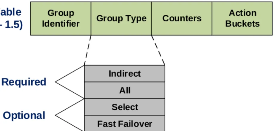
Like on the flow tables, the group table contains group entries (see Fig. 1.5) to match the incoming packet to the appropriate forwarding operation. Each group entry is identified by a group identifier given in integer values. Several counters are used to maintain the statistic of the packets treated by the group entry, similar to the counters field found in the flow tables. The forwarding instructions are handled by Action Buckets, in which a packet can be forwarded through a single or multiple ports (1 or more Action Buckets within a group entry), or to another
group entry (this action is a key component of one of the path establishment methods to be described later in this research).
Group
Identifier Group Type Counters
Group Table (OF 1.1 – 1.5) Action Buckets Indirect All Select Fast Failover Required Optional
Figure 1.5 - OpenFlow group table
There are 4 types of group entries in which 2 of them are required, and the rest are optional:
The Indirect type executes one defined bucket in a group. This allows for multiple flows or group entries to point to a common group identifier. With this group type, an OpenFlow switch can emulate a L3 behavior like pointing to a next hop for IP forwarding.
The All type executes all buckets that are present within a group. The packet is cloned for each bucket and sent to the output interface related to each bucket. With this group type, an OpenFlow switch can emulate multicast and broadcast forwarding.
The Select type executes one bucket of a set of buckets within a group. The bucket is selected based on a switch-computed selection algorithm like a hash function or simple round robin, rotating the use of each bucket for every incoming packet to achieve equal load sharing on the output interfaces related to the buckets. With this group type, an OpenFlow switch can emulate ECMP operations to load balance the traffic among its interfaces.
The Fast Failover type executes the first live bucket within a group. The liveness of a bucket depends on the state of the interface and/or group entry associated to the bucket. When an interface fails for some reason, the bucket goes down, and the group entry looks for the next live bucket to send the traffic. With this group type, an OpenFlow switch can emulate fast failover to backup links without consulting the SDN controller.
1.2.3 Meter tables
Since OpenFlow 1.3, the protocol introduces the capability of implementing several simple QoS operations like rate-limiting, or more complex like DiffServ (Differentiated Services). The meter table consists on a set of meter entries (see Fig. 1.6) that defines meters on per-flow basis. They measure the rate of packets associated to a specified meter, enabling rate control on the packets. The meters are associated with flow entries, in which each of the flow entries can specify a meter within its instruction field to execute rate control on incoming packets.
Meter
Identifier Meter Bands Counters
Meter Table (OF 1.3 – 1.5)
Band Type Rate Burst Counters Type Specific Arguments
Meter Bands
Figure 1.6 - OpenFlow meter table
The meter identifier is a 32 bit integer value that uniquely identifies the meter entry, the counters are the same used in flow and group tables and they are updated for every processed packet, and the meter bands are the set of instructions that specifies the rate of the band and the way to process the packet. The meter bands are subdivided into the following fields:
The Band Type field, which defines the way of how packets are processed. There are 2 band types available and they are all optional.
o Drop: discard the packet based on a rate limiter band.
o Dscp remark: Increase the drop priority of the DSCP field in the IP header of the packet. It may define a DiffServ Policer.
The Rate field, which selects the meter band, and specifies the lowest rate applicable for the meter band.
The Burst field, which specifies the granularity of the meter band.
The Counters field, which is the same type of counters as in the main table, but they are updated when a meter band process a packet.
The Type Specific Arguments field, which allocates optional arguments of some band types.
1.2.4 OpenFlow channel
According to the OpenFlow 1.3 specifications [3], the OF channel represents a logical interconnection between OpenFlow switches and an OpenFlow controller.
By means of this interconnection the controller configures and manage the switch for network configuration and packet forwarding, and receives events from the switches to identify network state and failures. A switch may support one or multiple OpenFlow channels for shared management between several controllers (i.e. when a switch is managed by a controller cluster).
The communication is handled through a messaging structure defined by the OpenFlow protocol for SouthBound interconnection. It is normally encrypted using TLS, but it can run directly through TCP without encryption.
1.2.4.1 OpenFlow messages
There are 3 message types supported by OpenFlow: “controller-to-switch”, “asynchronous”, and “symmetric” (see Table 1.1 for detailed message description of the message types).
Controller-to-switch messages are initialized by the controller, in which some of them may require a response from the switch. It monitors and manage the behavior of the switch.
Asynchronous messages are initialized by the switch to send update messages to the controller, which contains information regarding network events and changes on the switch state.
Symmetric messages can be initialized by either the controller or the switch, and sent without being required. They are usually used for OpenFlow devices discovery, and keep alive notifications.
Table 1.1 - OpenFlow message description
1.2.5 OpenFlow switch
The OpenFlow switch, is a logical switch that is comprised of one or more flow tables, group tables, meter tables, and one or more OpenFlow channels to interact to several controllers (see Fig. 1.7). The switch maintains communications with the controller, and the controller handles the switch operation using the OpenFlow protocol. The controller can add, modify, or delete flow entries in the flow tables in response to traffic behavior either reactively (in response to packets) or proactively (in anticipation to packets).
Figure 1.7 - Components of an OpenFlow switch4
As explained previously, each flow table is comprised of flow entries that the incoming packets will match according to the network information they carry, but the table lookup has to be done in order for the packets to be processed in a proper sequence (most packets may need to be processed by more than one flow entry that can be in separate flow tables). Therefore, OpenFlow establishes a linear sequence of flow tables known as the OpenFlow Pipeline (see Fig. 1.8), in which the packets will pass through different tables according to the match fields and the instructions found in the first flow entry.
Figure 1.8 - OpenFlow pipeline5
The flow tables are sequentially numbered starting at “0”, in which the incoming packets are first processed by this flow table. Then, depending on the outcome of the instructions in the flow entry of the first flow table, the packet can be forwarded to the next table (Table 1) and so on. Packets can only go forward through the pipeline, never backwards, due to the fact that the table processing the packet can only send it to a table of higher value than its own. On the other hand, a packet may be processed by only one table, and then be forwarded to an
4 Image retrieved from [3] 5 Image retrieved from [3]
output port, to the controller, or dropped without passing through the rest of the pipeline (depending on the instructions found in the matched flow entry).
During its processing through the pipeline, the packets will carry information of the metadata (register value to carry additional information between tables) and the action set, which can be modified when they are processed by a table using the Write-Action or Clear-Action instructions on the Instruction field. At the final table the actions within the action set are executed (Detailed diagrams about the pipeline and matching process can be found on Appendix A). Here is the order of action execution within the action set:
1. Copy TTL inwards
2. Pop (Apply all tag pop to the packet) 3. Push-MPLS (MPLS tag)
4. Push-PBB (PBB tag) 5. Push VLAN (VLAN tag) 6. Copy TTL outwards 7. Decrement TTL
8. Set (Apply all Set-Field actions) 9. QoS (Apply all QoS actions)
10. Group (Apply actions of the related group bucket into the order specified by the list)
11. Output (Forward the packet to the port specified by the Output action)
1.2.6 Openflow versions
To summarize the capabilities of the OpenFlow protocol, Table 1.2 illustrates the key features supported by the current versions of OpenFlow.
Table 1.2 - OpenFlow versions support description
With the support of group tables, MPLS actions like label manipulation, and the priority field of the flow table, make possible that an OpenFlow switch could emulate integrated platform behaviors like an MPLS LSR (necessary for adapting Segment Routing into SDN, see Chapter 4).
CHAPTER 2. PATH ESTABLISHMENT METHODS
This research defines path establishment methods as a general term to describe L2 and L3 routing techniques. Although routing traditionally implies L3 routing protocols, in SDN would also include L2 bridging since both achieves a common goal, to establish an end-to-end path in a network using path computation algorithms. The difference, is that L3 methods are IP-based routing, and L2 methods are MAC-based bridging. This chapter will introduce some fundamentals about routing and type of routing, the current standards in network performance, and the working principle of Proactive Forwarding, MPLS, and Segment Routing.
2.1 Routing fundamentals
Routing can be defined as “the act of moving information across and internetwork from a source to a destination” (Cisco Systems Inc., 1998). An ideal routing
process has to address certain goals, in which the result would have to represent the most efficient use of the network. Some of these goals includes the ability to choose optimal paths, to compute paths that has an efficient use of the bandwidth, and to exhibit high convergence after network changes. There are several types of routing that tries to approach these conditions like: Shortest Path routing, Multipath routing, and Source routing.
2.1.1 Shortest path routing
Shortest path routing defines best routes according to the cost of links that forms each path. The costs of each link in the network are determined by measurement standards called metrics, which usually are latency, link bandwidth, hop counts in the path, and sometimes the operational expenditures of each link (i.e. the use of rented link platforms like radio bridges). These metrics are related by the computation of a cost function that results on the total costs to be assigned for each link.
With the link costs assigned, shortest path protocols can use different routing algorithms to compute the best path between a pair of nodes in the network, and pick random paths if there is more than one best path of equal cost between the pair of nodes. Some of the most referred routing algorithms are Dijkstra’s and Bellman-Ford algorithms, used for Link-State and Distance-Vector based protocols, respectively.
2.1.2 Multipath routing
Multipath routing defines multiple alternative paths throughout the network in which the traffic can be forwarded to get to a common destination, increasing the available bandwidth, and improving fault tolerance and security. Investigations
suggest that the benefits of multipath routing are addressed to improve end-to-end reliability, congested paths avoidance, and adaptation to application performance requirements [5]. One of several strategies used in multipath routing is Equal-cost multi-path (ECMP).
2.1.2.1 Equal-cost multi-path (ECMP)
ECMP is based on delivering multipath routing throughout several paths when they offers the same cost in arriving to the destination. On this scenario, there is no preferable path to follow since each of them offers the same performance, besides, the multiple paths to choose from are most probably the best paths computed by shortest path routing. Therefore, what ECMP does, is to share the traffic flow among the available links using either random or round-robin (cyclic order of links) selection. This allows for the network to load-balance the traffic throughout sections where redundant links, or complete redundant paths are available, achieving fault tolerance, high availability, and increased throughput. ECMP is more generally used as an additional feature of several routing protocols like Open Shortest Path First (OSPF), and Intermediate System-to-Intermediate System (IS-IS), which are shortest-path based routing protocols.
2.1.3 Source routing
Source routing is a type of routing that allows a source network device to process and define a partial or complete route through the network for packet forwarding, instead of being processed by every intermediate device in the network. The entire path of each packet is known when they are injected into the network, being the routing information added to the packet header to avoid local routing decisions at each hop [6].
In basic terms, the source routing operation is based on a list of intermediate devices and links within the packet header at the source forwarding device, in which the list represents an ordered sequence of hops where the packet will traverse until it reaches the destination. Within this sequence or route, source routing can allow for concurrent use of multiple paths in the network, being the sender device capable to choose different routes on a per-packet basis. Some investigations points out that for SDN environments, source routing can be an alternative method for packet forwarding than traditional OpenFlow instantiation [7].
2.2 Network performance standards
From the point of view of the customer, network performance can be a little subjective, since it is a measurement of the service quality perceived by him/her (better known as Quality of Experience, or QoE). From this perspective, network performance parameters have been observed for values that limits the customer perception between optimal and degraded communications. These parameters
are used to determine the QoS levels to be assigned to each type of traffic, and the reference to follow for service level agreements (SLAs) between network service providers and customers. The main parameters used to measure network performance are: Bandwidth, Throughput, Delay, Jitter, and Packet Loss.
The Bandwidth in computer networks is the available bitrate or channel capacity of a communications link expressed in bits per second (bps). It can also refers to the transmitted information capacity in bits per second.
The Throughput in computer networks is the transmitted or consumed bandwidth in the network expressed in bits per second. When a traffic transmitted at a line rate speed is measured, the maximum bandwidth received over an end-to-end communication is the throughput that the network delivers for that communication.
The Delay is the time interval between the transmission and reception of a packet. There are 2 types of delays in computer networks:
o One-way delay: Time interval of a packet to traverse the network from a source to a destination. It is difficult to measure since both end points (source and destination), have to be synchronized in time through a reference clock, in which its accuracy can be expensive and hard to achieve. This delay is more accurate to measure the response of the network in front of situations like link failures, or to monitor that the network is complying with the stipulated SLA.
o Round Trip Time (RTT): Time interval of a packet to traverse the network from a source to a destination and return back to the source. RTT is most commonly used since is easier to measure from most end devices, but is less accurate to perceive the response of a network in front of failures. This doesn’t mean that One-way delay is RTT/2, since the trip and return delays may not be the same.
The Jitter is the variation of the delay perceived in an end-to-end communication. From the point of view of the transmission, packets traversing at a fixed bitrate denotes a periodic transmission, in which the jitter represents a variation of that periodicity. This parameter, is less desirable in computer networks since it can degrade sensible traffic like voice and video, which depends greatly on real time communications.
The Packet Loss, like the name states, is the amount of packets that have been lost during transmission over the network, either for errors in the transmission, or for the network capacity to handle the traffic in terms of bandwidth and throughput.
There are all kinds of traffic that can traverse throughout the network, and each of them with their own demands in network performance to guarantee the desired QoS and SLA. To test the network to cover all these demands, is better to focus on the demands of the most critical type of traffic, the voice traffic. Voice communication is the most sensible traffic, because all voice packets have to be sent in real time over the network. If there is considerable delay and jitter, or if there is not enough guaranteed bandwidth, the voice communication degrades
easily, perceiving gaps in the sound or interruptions. According to several vendors and ITU recommendations, the following table represents the desired parameters to ensure proper network performance for Voice over IP (VoIP) communications.
Table 2.1 - Network performance parameters Network performance for VoIP
One-way Delay ≤ 150ms
Packet Loss ≤ 1%
Jitter ≤ 30ms
Guaranteed Bandwidth 21Kbps to 320Kbps
The one-way delay limit is specified by the ITU-T G.114 recommendation [8], which is acceptable for most user applications. Even levels of delays up to 400ms can be accepted for several types of traffic, but network providers have to be aware of possible impacts over the transmission quality. There is no direct consent about a standard limit for jitter, but several vendors like Cisco Systems Inc. [9], have developed several testing, and their results suggest that voice communications tends to start degrading on jitter values greater than 30ms. As for guaranteed bandwidth, it is variable for any kind of communication in which providers have to guarantee that the physical link can cover for all desired traffic. For the purpose of this research, the values of network performance for VoIP communications are used as a reference, to compare network performance measurements on the path establishment methods described in Chapter 5.
2.3 Proactive Forwarding (PF)
Proactive forwarding is defined in this research as a global term to describe path establishment methods that use OpenFlow proactive instantiation, defining flow rules in L2 switches in anticipation of traffic, and constructing end-to-end paths on an SDN network. Generally on most SDN vendors, proactive forwarding is a shortest path routing type, in which Dijkstra based algorithms are used for path computation.
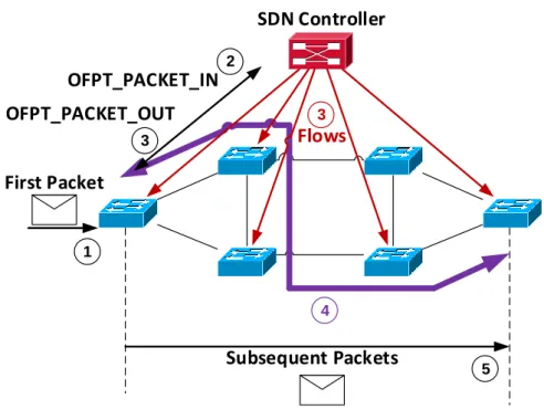
The basic function of proactive forwarding methods, is to establish end-to-end paths using the source and destination MAC addresses, defining flow entries to be added on the flow tables of the switches for pipeline processing. Only the involved switches in the path will receive this update on their flow tables in order to define forwarding actions according to the match field of the flow entries. The SDN controller will start this process once received the first packet, and then in anticipation of the rest of the traffic, the controller downloads all necessary flows to the involved switches to establish the path (see Fig. 2.1).
Flows SDN Controller 1 2 OFPT_PACKET_IN 3 4 First Packet 5 Subsequent Packets 3 OFPT_PACKET_OUT
Figure 2.1 - Proactive forwarding model
The switch receiving the first packet will not know the route to follow to a destination. When this happens, the switch attaches the packet into an OpenFlow message (OFPT_PACKET_IN) and send it to the controller to consult the route to take for the packet, and subsequent packets with the same destination. Using the MAC address information stored in the packet header, the SDN controller computes the shortest path (least-cost path) to the destination based on metrics like hop count, link bandwidth, and delay.
After the path computation, the SDN controller defines the necessary flow instructions and send them to the involved switches in the path, in parallel with an OFPT_PACKET_OUT message to the first switch in response of the OFPT_PACKET_IN message, defining the forwarding action of the first packet. With the flow entries downloaded into the switches flow tables, the end-to-end path is established allowing for subsequent packets with the same source and destination address information, be forwarded throughout the network without consulting the SDN controller.
With difference of OpenFlow reactive instantiation, in which flow entries have expiration time for unused paths, proactive instantiation maintains the flow entries, and hence preserves the path indefinitely until there is a change in the physical path. Examples of practical applications of proactive forwarding includes: L2 Switch application or OpenStack network abstraction in OpenDaylight controllers, Intent forwarding application in ONOS controllers, and NOX proactive mode in NOX controllers.
2.4 Multiprotocol Label Switching (MPLS)
MPLS is an architecture that defines a mechanism to perform label switching, in which handles the combination of L2 packet forwarding and L3 routing [11]. It assigns labels to packets for their transportation across packet-based or cell-based networks. Label swapping is the forwarding mechanism used throughout the network, in which data information carry a short and fix-length label that instructs switching nodes how to process and forward the packets along the path.
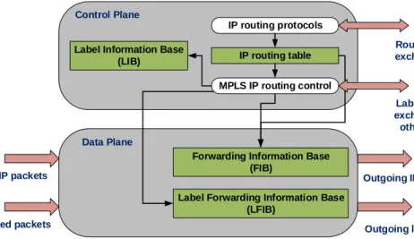
2.4.1 MPLS architecture
The architecture is a distributed system, where each node within the MPLS domain is divided into two main components: the data plane and control plane. The data plane maintains a label-forwarding database (FIB and LFIB tables) to perform the packet forwarding based on the labels carried by the packets. The control plane, creates and maintains label-forwarding information (LIB table) among a group of interconnected nodes. Fig. 2.2 illustrates the basic architecture of an MPLS node.
IP routing table
Forwarding Information Base (FIB)
IP routing protocols
MPLS IP routing control
Label Forwarding Information Base (LFIB)
Label Information Base (LIB) Control Plane Data Plane Label binding exchange with other nodes Routing information exchange with other
nodes
Incoming IP packets
Incoming labeled packets Outgoing labeled packets
Outgoing IP packets
Figure 2.2 - MPLS architecture6
Every MPLS node runs one or more IP routing protocols to exchange IP routing information between them, making every node an IP router in the control plane. This exchange, allows the nodes to identify the networks attached to each node and determine where to send the packets through the use of labels. The nodes exchange label information, in which they store the mappings of labels assigned by a local node with the labels received from its neighbors into a Label Information Base (LIB). These mappings are distributed within the MPLS domain through the use of the Label-Distribution Protocol (LDP).
During packet forwarding, not all the labels within the LIB table are needed. In this sense a table in the data plane is used (the LFIB table), where it pulls out only the necessary label mapping information from the LIB table, performing the packet forwarding operation of the current traffic for a current established path. The IP routing table is used with the MPLS IP routing control process to build the FIB table, which is an IP forwarding table augmented with labeling information in order to introduce labels to ingress packets or remove labels from egress packets (functionality used in edge nodes), and send them either outside or inside the MPLS domain.
2.4.2 MPLS topology
The control and data plane operation in each MPLS node, brings together the traffic forwarding operation of the entire MPLS domain. The following figure, contemplates the MPLS model which constitutes its forwarding operation and topology. Edge-LSR LSR LSR LSR LSR 1 2 5 PUSH POP IP Packet IP Packet L1 3 SWAP IP Packet L2 4 SWAP IP Packet L3 PHP 6 IP Packet LSP Edge-LSR Figure 2.3 - MPLS model
In the MPLS domain, all nodes are designated as Label Switch Router (LSR), in which the edge nodes are commonly identified as Edge-LSR. The difference in operation, is that Edge-LSRs prepend or remove labels from the IP packets by using the FIB table for IP and Label based forwarding. In this manner, the Edge-LSR serves as an intermediary between the MPLS domain and other routing domains like IGP (Interior Gateway Protocols) and EGP (Exterior Gateway Protocols) domains. The rest of the LSR within the MPLS domain, executes only label based forwarding operations like the SWAP action.
The ingress IP packets are attached to a label by the Edge-LSR using the PUSH action. Then the Edge-LSR sends the packet to the next hop according to the
label information, in which the subsequent hops (LSRs) replace label information through the SWAP action for every next hop that the packet traverse. Finally, depending on the configuration made on the nodes, the POP action (removal of the label) can be performed by either the Edge-LSR or by the hop before it, in which the POP action is known as Penultimate Hop Popping (PHP). The entire forwarding process according to the labels information, establishes and end-to-end path within the MPLS domain referred as a Label Switched Path (LSP). Several LSPs can be established by the use of path computation algorithms or manual configuration that can be used for different purposes including VPN routing, traffic engineering, and QoS.
2.5 Segment Routing (SR)
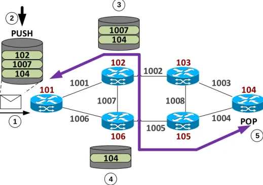
Segment Routing is a new source routing method that is being developed by the IETF to be supported on several routing protocols running today. In principle, an intermediate device or SR node, guides the packet through an ordered sequence of instructions called segments [12]. A segment can be any topological or service-based instruction, in which the packet will be treated according to the sequence found on its header (see Fig. 2.2). It can be applied to both MPLS and IPv6 architectures, in which would only require small changes into their forwarding planes. 1008 1007 1006 1004 102 1007 104 101 102 103 104 105 106 1001 1003 1005 1007 104 104 1 2 3 4 5 PUSH POP 1002
Figure 2.4 - Segment Routing model
As described in the general functionality of source routing, segment routing constructs the end-to-end path based on a list of segments that are identified by an integer value called the segment identifier (SID), which also identifies a network element (SR node, group of nodes, SR domain, link, and set of links)
that is going to apply the segment instruction. Each segment is executed by the SR node on any incoming packet. Following the above model (Fig. 2.2), the ingress SR node introduces the list of segments into the incoming packet. The list denotes 3 segments or instructions that are going to be executed by nodes 102 and 104. The order of execution goes from top to bottom. Node 102 will receive the packet, execute and pull out the first and second instruction from the list and send the packet through link 1007, nodes 106 and 105 will forward the packet to node 104 without executing the remaining instruction, and node 104 will pull the final segment stored in the stack and forwards the packet to the desired destination.
A segment involves actions like forwarding a packet according to shortest path destination, an interface, or an application/service instance. An SID can be an MPLS label, an index value on the MPLS label space, or an IPv6 address, depending of the data plane that segment routing uses.
2.5.1 Segment list
An ordered list of SIDs that encodes the topological and service-based source route of the packet. Depending of the data plane used, it could be and MPLS label stack, or a list of IPv6 addresses. In the top of the list lies the active segment, which is the instruction the must be executed by the receiving SR node to process the packet. During the packet transit through the path, the following actions can be executed on the segment list: Push, Next, Continue, and POP.
The Push action is executed by an SR node to introduce a segment into the segment list.
The Next action is used when an active segment is completed, defining the next segment in the list as the active segment.
The Continue action, is used when the current active segment is not yet completed, and maintains its state as an active segment. One example is when an SR node receives a packet with segments that is not up to the node to execute any of them, forwarding the packet to the node that supposed to execute the active segment (i.e. nodes 106 and 105 of Figure 2.2).
The POP action is used at the edge node to remove the final segment from the segment list, and send the packet to its final destination. In the MPLS data plane, the node previous to the edge node can perform this action (PHP).
2.5.1.1 SR Tunnel
Is a segment list specified with abstract constrains (like delay or priority) pushed on a packet to define a route that can be used for traffic engineering, OAM, or FRR reasons. SR tunnels can be configured manually by the operator.
2.5.2 Segment types
Segments can be classified in two categories: local and global segments.
The Local segments are the ones that are originated by an individual node and they are only supported by that node. Examples of these segments are those related to links directly connected to the SR node.
The Global segments are the ones that their related instructions are supported by all SR-capable nodes in the domain [12]. It can be used to identify a group of nodes that can handle a specific instruction, and relate their local SIDs to a global SID.
Besides local and global segments, they can also be classified in two types: IGP segments and BGP peering segments. BGP peering segments are out of the scope of this research, so they will not be discussed. The IGP segments are the ones advertised by an SR node for its attached prefixes and adjacencies within a link-state IGP domain, and their classification can be observed on Fig 2.5:
Figure 2.5 - IGP segments classification
The IGP-Prefix segments are global segments attached to an IGP-Prefix such as a summarized network addresses that are advertised within the IGP domain. IGP-Anycast and IGP-Node segments are the two types of the described segments, in which Anycast segments identifies a group of nodes by an Anycast SID, and the Node segments identifies a single node using a Node-SID (usually related with the node’s loopback address).
The IGP-Adjacency segments are local segments attached to a unidirectional or a set of unidirectional adjacencies, and they are identified using an Adj-SID (adjacency segment identifier). The adjacency is formed by the interconnection
of a local node and its neighbor, and it can be advertised throughout the SR domain.
When a packet is following the segment list and finds an Adj-SID of a specific node, it means that the action that the node will take for the packet is to forward it through the adjacency (link interface) assigned to the Adj-SID. If there is more than one adjacency assigned to the Adj-SID (set of link interfaces), the node will load balance the traffic through the set of adjacencies. This gives two options of encoding the Adj-SID: to reference the use of protection in the adjacency (IPFRR or MPLS-FRR), and to identify an adjacency as a local segment.
2.5.3 Path computation algorithms
There are two routing algorithms defined for segment routing: Shortest Path and Strict Shortest Path.
Shortest Path is the default algorithm, in which a packet is forwarded along the well-known ECMP-aware SPF algorithm. It has the flexibility that an intermediate device can implement a policy-based forwarding action that can override the SPF decision.
Strict Shortest Path works the same as the default shortest path algorithm, but instructing each intermediate device to ignore any local policy-based forwarding actions overriding the SPF decision.
Prefix-SID advertisement includes a set of flags and an algorithm field, in which associates a given Prefix-SID (Anycast or Node) to either routing algorithms. An ingress node gathers in this way all nodes and adjacencies information from the Prefix-SID advertisements, and the routing algorithm constructs the end-to-end path for any traffic incoming to the SR domain.
CHAPTER 3. TEST TOPOLOGY SETUP
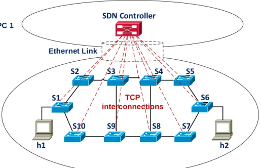
The general idea to measure the behavior of path methods in front of network events, is to provide a scenario where an end-to-end communication is available through multiple paths. A virtual network topology was built to meet these conditions, and is presented on Fig. 3.1. The network topology is contained within 2 physical computers, in which one of them runs an SDN controller, and the other the infrastructure layer. The forwarding plane is comprised of 10 L2 virtual switches interconnected with the SDN controller, using a TCP port per switch-controller connection over a single physical Ethernet link, 2 virtual hosts (h1 and h2) from where the end-to-end communication is taken place, and 12 virtual Ethernet links interconnecting the switches.
S1 S2 S3 S4 S5 S6 S7 S9 S10 h1 h2 SDN Controller S8 PC 1 PC 2 Ethernet Link TCP interconnections
Figure 3.1 - General test network topology
The links disposition allows the SDN controller for the computation of 8 possible paths between hosts h1 and h2 as listed below.
1) S1, S2, S3, S4, S5, S6 2) S1, S10, S9, S8, S7, S6 3) S1, S2, S3, S9, S8, S7, S6 4) S1, S2, S3, S4, S8, S7, S6 5) S1, S10, S9, S3, S4, S5, S6 6) S1, S10, S9, S8, S4, S5, S6 7) S1, S2, S3, S9, S8, S4, S5, S6 8) S1, S10, S9, S3, S4, S8, S7, S6
This chapter, describes the main hardware used to build this topology, the measurement tools used for the experimentations, the SDN controllers selected
for the configuration of path establishment methods, and their setup over the network topology.
3.1 Control layer involved elements
The main purpose of using two computers, is to isolate the processing load of the SDN controller under one hardware. This allows to measure the controller’s response to the network without being affected by other mayor processes external to the normal operation of the computer. The same situation applies to the infrastructure layer, in which one computer can dedicates its hardware resources for the data plane processing, and ensure the network performance in terms of packet forwarding as realistic as possible. Therefore, an SDN controller is selected and hence, its related hardware to support its processing demands.
3.1.1 SDN controller selection
Since Segment Routing is a relative new method, the main idea in this project was to find a complete adaptation of Segment Routing to SDN. Several controllers were observed, along with their project developments. There were two options for the SDN controller: OpenDaylight and ONOS.
OpenDaylight, is a modular and multiprotocol controller infrastructure built for SDN deployments on multi-vendor networks. It has mayor development effort through a community sponsored by several vendors like Cisco, Brocade, HP, Huawei, Vmware, and Oracle.
ONOS, or Open Network Operating System, is a modular and distributed core controller infrastructure targeted for service providers and mission-critical networks, with the mission of ensuring high availability, scale-out and performance to the service provider’s network. It has been developed by the Open Networking Lab (ON.Lab) in coordination with service providers like AT&T, and network vendors like Ericsson, Cisco and Huawei.
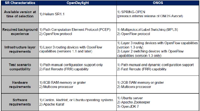
Since both controllers have full capabilities to manage the Proactive Forwarding method, the selection criteria was based on how the way in handling Segment Routing, allows for more flexibility to implement the test topology and the measurements made in this research. Table 3.1 displays a comparison of both platforms in terms of Segment Routing capabilities, hardware requirements, and compatibility with the test scenario:
Table 3.1 - SDN controller selection criteria
Based on the characteristics observed, the SDN controller selected for the experimentation was the ONOS controller. There were several factors taken into account, in which the main reasons for selection were the following:
The Segment Routing version of ONOS is designed to work over MPLS, in which previous knowledge of this architecture gave more understanding of the working principle of Segment Routing, and its operation on an SDN network. The ONOS controller gives more flexibility to build the infrastructure layer,
since it’s capable of configuring OpenFlow switches to emulate L3 routing devices. During the selection, there were no OpenFlow routing devices available to work with OpenDaylight.
The Segment Routing version of ONOS can install end-to-end paths both dynamically and manually, which gives more flexibility in the experimentation, since it is not necessary to manually configure several routes during failure recovery scenarios.
The ONOS controller requires less hardware resources than OpenDaylight. Knowing that ONOS was the desired platform for the experimentation process, the final versions selected for Segment Routing and Proactive Forwarding methods were the following:
Segment Routing: ONOS version SPRING-OPEN
Proactive Forwarding: ONOS version Blackbird 1.1.0rc2
Since the SPRING-OPEN version is an experimental operating system only used for the adaptation of Segment Routing, it doesn’t support Proactive Forwarding.
For this reason, it is used a different version of ONOS (a public release version) to test Proactive Forwarding. Taking into account that the purpose of the investigation is a conceptual analysis of the methods working principle, the accuracy demand of testing both methods under the same platform is not considered mandatory, nevertheless both methods are tested under the same platform type, which is the ONOS architecture. This gives an idea of what could be the effects of Segment Routing in ONOS controllers compared with Proactive Forwarding.
3.1.2 Controller’s hardware
Both ONOS versions require the same hardware resources to ensure minimum optimal operations. For this purpose, a high resource computer is selected to host both versions. This computer is purposed for high load processing, and it was available at the UPC campus to be used in this experimentation. The computer’s specifications are the following:
3.4GHz Intel® Core™ i7-3770 processor 16GB RAM memory
64bit Ubuntu server 14.04.01 operative system 1Gbps Ethernet NIC
IEEE 802.11n Wireless NIC
With this computer, it is ensured that the normal operation of the ONOS controllers is not affected by limitations in the hardware resources, and hence the measurements of the controller’s time response. Both versions are installed in this computer, but they are initialized one at a time to ensure this performance.
3.1.3 Controller’s software
Table 3.2, shows the software requirements for each of the selected ONOS versions:
Table 3.2 - ONOS software requirements
ONOS versions Blackbird 1.1.0rc2 SPRING-OPEN
Requirements 1) Apache Karaf 3.0.2 2) Java 8 JDK 3) Apache Maven 3.2.3 4) Git 5) Bash 1) Apache Zookeeper 3.4.6 2) OpenJDK 7 3) Git