Evaluation of Transient Response for Rotary Inverted Pendulum Positioning using Fuzzy Logic Controller International Journal of Electrical Engineering and Applied Sciences, Vol. 1, No. 1
April 2018
1
Mohd Shahrieel Mohd Aras*,
2Marizan Sulaiman,
3Alias Khamis,
4Mohd Hendra
Hairi,
5Mariam Md Ghazaly,
6Mohd Khairi Mohd Zambri,
7Hairol Nizam Mohd
Shah
1,2,3,4,5,6,7Centre for Robotic and Industrial Automation (CeRIA), Fakulti Kejuruteraan Elektrik,
Universiti Teknikal Malaysia Melaka (UTeM)
*corresponding authors: [email protected]
Abstract
– The rotary inverted pendulum is one of the fundamental problems existing in the field
of Control Engineering. This mechanism possesses a high degree of non-linearity and hence, it is a highly unstable system. The basic control intention of the rotary inverted pendulum is to sustain the unstable equilibrium position. Since the rotary inverted pendulum is an under-actuated mechanism, the control can be done regulating the force applied to the actuator. In this paper, the mathematical model of the mechanism is presented. From the mathematical model, the fuzzy logic controller scheme was developed. A comparison of the performance of fuzzy logic controller and PID controller was presented. The performance of the proposed control algorithms was evaluated by means of digital simulation through MATLAB/Simulink.Keywords
:
Rotary inverted pendulum, fuzzy logic controller, transient response.Article History
Received 17 November 2017
Received in revised form 9 January 2018 Accepted 24 January 2018
I.
Introduction
The inverted pendulum is one of the few mechanisms that is gaining more and more attention lately. Generally, it is an open-loop and closed-loop unstable system with the highly non-linear system in nature [1-2]. Apart from that, inverted pendulum system is an example of under-actuated mechanical system which has fewer control inputs rather than its degree of freedom. The inverted pendulum system was early studied when there is a need to design a controller to maintain the balance of rockets during vertical take-off. During the launching of a rocket, the thrust force that pulls the rocket move upwards is opposing the gravitational force, causing the rocket is extremely unstable. Similarly, the inverted pendulum requires a continuous correction mechanism to stay upright as the system is unstable in open loop configuration. Although the inverted pendulum system is difficult in control, researchers are keen on its advantages in development in wide range applications such as robotics, aerospace engineering and marine engineering. As the inverted pendulum system is essentially unstable, therefore the main issue of inverted pendulum system is that how is it necessary to control the inverted pendulum so that its equilibrium at the steady state conditions.
Typically, the inverted pendulum system has two classical form which is linear inverted pendulum (LIP) and rotary inverted pendulum (RIP) [3]. LIP systems are running on the straight path to balance the pole whereas the RIP systems are performing swing up. The simple linear pendulum has long proved a useful model for more complicated physical systems, and its behavior in the small-amplitude limit provides a realistic yet solvable example for students in introductory classes. Although the force-free, frictionless pendulum can be solved exactly for all amplitudes in terms of elliptic integrals, the solution is found that less useful when taking into consideration of damping and external driving [4]. Yet, the studies on the details of the rich non-linear dynamics of the damped, force-driven pendulum can be done easily nowadays with the advancement of the desktop computer. In this journal, the control of rotary inverted pendulum using a fuzzy logic controller is discussed.
II.
Rotary Inverted Pendulum
Generally, Rotary Inverted Pendulum system (RIP) consists of a driven arm which rotates in the horizontal plane and a pendulum mounted on a hinge that is free to rotate in the vertical plane [5-7]. Other than that, the advantage of the small workspace required has made itEvaluation of Transient Response for Rotary Inverted Pendulum
ISSN: 2600 - 7495 IJEEAS, Vol. 1, No. 1, April 2018
International Journal of Electrical Engineering and Applied Sciences
10
M. S. M Aras et. al.
journal.utem.edu.my |ISSN 2600-7495 widely implemented in conventional cart type pendulum
system as the pendulum has a circular trajectory. In the field of control theory, the inverted pendulum control is one of the fundamental which is very interesting yet challenging topic. The rotary inverted pendulum is a very good model for the attitude control of a space booster rocket and a satellite, automatic aircraft landing system, aircraft stabilization in the turbulent air-flow, stabilization of a cabin in a ship and so on. However, in order to solve such problem with a non-linear time variant system, alternatives such as real-time computer simulation of these equations or linearization must be used. Apart from that, it also has its own deficiency due to its properties of non-linear and unstable in control system.
Up until today, many techniques have been undertaken to stabilize the linear inverted pendulum system as well as rotary inverted pendulum system. Figure 1 shows the rotary inverted pendulum which is driven by a rotary servo motor system (EMECS). Basically, the servo motor drives an independent output gear whose angular position is measured by an encoder. The second encoder is attached at the end of the pendulum arm which measures the angular position of the pendulum. The system is interfaced by means of a data acquisition card and driven by MATLAB/Simulink based real-time software.
Fig. 1. EMECS Inverted Pendulum by Terasoft Inc.
III.
Fuzzy Logic Controller
A fuzzy logic controller is a biologically inspired controller scheme which is derived based on the cognitive psychology of human brain. The term fuzzy refers to the indistinctive concept that exists between the logical value of “true” or “false”. The construction of the controller is designed to imitate the human inference capability, a process in which human reaching a conclusion based on what they know. One of the main advantages of this modern control scheme is that human know-how are able to be implemented during the controller design stage since the solution to the problem is understandable by human. Hence, a significant increase of fuzzy logic implementation can be observed over the years. Deployment of fuzzy logic control covers a wide range of industry sectors such as aerospace, engineering, automotive and oil, gas and geosciences [8-14].
Fig. 2. Basic Configuration of Fuzzy Logic Controller. Fuzzy Logic controller scheme comprises of four main entities namely the fuzzification element, knowledge base, inference engine and the defuzzification element. The basic structure of fuzzy logic control is as depicted in Figure 2.
The fuzzification element serves as the overriding body to translate the system’s variable into appropriate linguistic variables understandable by the controller. On the other hand, the defuzzification element operates in a manner that is vice versa to the fuzzification element. The defuzzification element translates back linguistic variable into system variables. The knowledge base is a methodical expression of vague antecedents and consequents. These expressions are represented through linguistic variables and are classified as rules. The inference engine is the decision-making part of the controller in which all the conclusions are reached based on the rules governed by the knowledge base.
IV.
Mathematical Modeling of Rotary
Inverted Pendulum
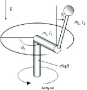
Figure 3 shows a free body diagram of the Rotary Inverted Pendulum. The system variables and parameters are defined in Table 1:
Fig. 3. Simplified Rotary Inverted Pendulum.
From the derivation and linearization of the system model, we can obtain a state space representation of the rotary motion inverted pendulum system which is given as follows:
Evaluation of Transient Response for Rotary Inverted Pendulum Positioning using Fuzzy Logic ControllerM. S. M Aras et. al.
journal.utem.edu.my |ISSN 2600-7495 (1)
Where, 𝑎𝑎=𝐽𝐽𝑒𝑒𝑞𝑞+𝑚𝑚𝑟𝑟2, 𝑏𝑏=𝑚𝑚𝐿𝐿𝑟𝑟, 𝑐𝑐=4/3𝑚𝑚𝐿𝐿2, 𝑑𝑑=𝑚𝑚𝑔𝑔𝐿𝐿,
𝐸𝐸=𝑎𝑎𝑐𝑐−𝑏𝑏2, 𝐺𝐺=𝜂𝜂𝑚𝑚𝜂𝜂𝑔𝑔𝐾𝐾𝑡𝑡𝐾𝐾𝑚𝑚𝐾𝐾𝑔𝑔2−𝐵𝐵𝑒𝑒𝑞𝑞𝑅𝑅𝑚𝑚𝑅𝑅𝑚𝑚. The following table shows the typical configuration of the system.
TABLE 1:
TYPICAL CONFIGURATION OF THE SYSTEM.
Based on the typical configuration of the SRV02 and the pendulum system, the above state space representation of the system can be written as follow:
(2)
(3) Hence, based on the state space equation, it is possible to derive the following transfer function which describes the change of angular position of the pendulum with respect to the input voltage.
(4)
V.
FLC Design
The design of fuzzy logic controller can be broken down into few different components which are the fuzzification, defuzzification, inference engine, and rule base. The design takes into consideration of selecting and processing the inputs and outputs of the controller. In this paper, the processing of input and outputs of the controller were emphasized. The fuzzy controller was developed via the MATLAB and Simulink software operating in Windows environment as shown in Figure 4.
Fig. 4. Simulink Block Diagram.
Mamdani’s fuzzy inference method was utilized in this research. This method explores the expectations of the output membership functions to be defined as fuzzy sets. Defuzzification would be required to define the fuzzy sets for each output variable into crisp sets throughout the aggregation process. The universe of discourse of the variables are defined and normalized to cover the range described as follows:
a. Error: [-300 300]
b. Rate of Change of Error: [-300 300] c. Output: [-10 10]
Standard choice of membership functions was selected with three membership functions for the fuzzy variables. Gaussian membership function was chosen to represent error and triangular membership function was chosen to represent the rate of change of error and output. The three membership functions defined would generate a total of 9 rules in the rule base (32 = 9). Figure 5, 6 and 7 shows the membership functions for error, the rate of change of error and output.
Fig. 5. Initial Membership function for error.
Fig. 6. Initial Membership function for error integral M. S. M Aras et. al.
journal.utem.edu.my |ISSN 2600-7495 (1)
Where, 𝑎𝑎=𝐽𝐽𝑒𝑒𝑞𝑞+𝑚𝑚𝑟𝑟2, 𝑏𝑏=𝑚𝑚𝐿𝐿𝑟𝑟, 𝑐𝑐=4/3𝑚𝑚𝐿𝐿2, 𝑑𝑑=𝑚𝑚𝑔𝑔𝐿𝐿,
𝐸𝐸=𝑎𝑎𝑐𝑐−𝑏𝑏2, 𝐺𝐺=𝜂𝜂𝑚𝑚𝜂𝜂𝑔𝑔𝐾𝐾𝑡𝑡𝐾𝐾𝑚𝑚𝐾𝐾𝑔𝑔2−𝐵𝐵𝑒𝑒𝑞𝑞𝑅𝑅𝑚𝑚𝑅𝑅𝑚𝑚. The following table shows the typical configuration of the system.
TABLE 1:
TYPICAL CONFIGURATION OF THE SYSTEM.
Based on the typical configuration of the SRV02 and the pendulum system, the above state space representation of the system can be written as follow:
(2)
(3) Hence, based on the state space equation, it is possible to derive the following transfer function which describes the change of angular position of the pendulum with respect to the input voltage.
(4)
V.
FLC Design
The design of fuzzy logic controller can be broken down into few different components which are the fuzzification, defuzzification, inference engine, and rule base. The design takes into consideration of selecting and processing the inputs and outputs of the controller. In this paper, the processing of input and outputs of the controller were emphasized. The fuzzy controller was developed via the MATLAB and Simulink software operating in Windows environment as shown in Figure 4.
Fig. 4. Simulink Block Diagram.
Mamdani’s fuzzy inference method was utilized in this research. This method explores the expectations of the output membership functions to be defined as fuzzy sets. Defuzzification would be required to define the fuzzy sets for each output variable into crisp sets throughout the aggregation process. The universe of discourse of the variables are defined and normalized to cover the range described as follows:
a. Error: [-300 300]
b. Rate of Change of Error: [-300 300] c. Output: [-10 10]
Standard choice of membership functions was selected with three membership functions for the fuzzy variables. Gaussian membership function was chosen to represent error and triangular membership function was chosen to represent the rate of change of error and output. The three membership functions defined would generate a total of 9 rules in the rule base (32 = 9). Figure 5, 6 and 7 shows the membership functions for error, the rate of change of error and output.
Fig. 5. Initial Membership function for error.
ISSN: 2600 - 7495 IJEEAS, Vol. 1, No. 1, April 2018
International Journal of Electrical Engineering and Applied Sciences
12
M. S. M Aras et. al.
journal.utem.edu.my |ISSN 2600-7495 Fig. 7. Initial Membership function for output.
The rule base was implemented by sets of IF-THEN type of rule. The rules were determined heuristically based on the understanding of the system. An example of IF-THEN rule is provided as follows:
IF error, e is negative small (NS) and rate of change of error, ∫ 𝑒𝑒 is positive small (PS) THEN output is zero (Z).
This rule quantifies the situation where the pendulum is near to the right of the vertical and it is moving clockwise, hence a small force (to the right) is needed to counteract the movement of the pendulum so that it moves toward zero. Table 2 shows the rules defined for rule base of the fuzzy controller.
TABLE 2:
RULE BASE FOR FUZZY CONTROLLER.
Figure 8 shows the rule viewer available in the MATLAB software. The tuning of the fuzzy controller was performed by adjusting the range of the input and output. The rule viewer in MATLAB serves as a guide for adjustments to be made.
Fig. 8. MATLAB rule viewer.
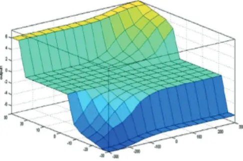
Figure 9 and 10 shows the surface view of rules before and after the tuning process. The surface view is a plot that correlates all fuzzy variables into a three-dimensional figure. Hence, the surface view in Figure 9 and 10 provides an information of the correlation between output with respect to the error and the rate of change of error.
Fig. 9. Surface view of the rules before tuning.
Fig. 10. Surface view of the rules after tuning.
In order to obtain the crisp sets, the center of gravity defuzzification method was employed. The crisp value obtained from the defuzzification is the resultant output of the fuzzy controller.
VI.
Results and Discussion
Figure 11, 12 and 13 show the results of the initial tuning of the fuzzy controller. Trial and error method was employed in the tuning process. Analysis of the responses obtained from the simulations are documented as follows.
Evaluation of Transient Response for Rotary Inverted Pendulum Positioning using Fuzzy Logic ControllerM. S. M Aras et. al.
Fig. 11. Response from error MF tuning.
Figure 11 shows the step response of the system as a result of the tuning of error membership function. Based on Figure 11, the input response of the PID controller was better than the fuzzy logic controller input. The PID controller was able to perform without any steady-state error except for the low degree of observable overshoot. However, the tuning of error membership function did not yield a satisfactory result whereby a large steady-state error and bad transient response in terms of settling time were observed. Hence, the error integral or the output membership function is tuned to improve the results.
Fig. 12. Response from error integral MF tuning. Figure 12 shows the step response of the system as a result of the tuning of the rate of change of error membership function. It can be observed that the rate of change of error membership functions tuning yielded a better step response result. However, the large margin of steady-state error suggests that further tuning is required to obtain a better performance.
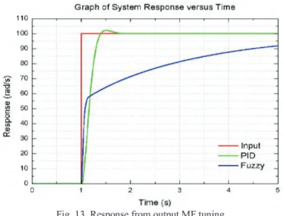
Fig. 13. Response from output MF tuning.
The tuning of the output membership function yielded a similar response in comparison to the previous tuning as shown in Figure 13. Since a large steady-state error was still observable, further tuning is warranted.
The overshoot of the response indicates that a higher force was exerted by the actuator in the opposite direction to counter the pendulum motion. The rising time indicates how fast the system can counteract the disturbance that caused the pendulum to sway from its equilibrium position. On the other hand, the settling time highlights the required time for the system to stabilize when a disturbance is observed. Hence, the previous results showed that the fuzzy controller was still unable to perform well. Further tuning was then performed to improve the performance.
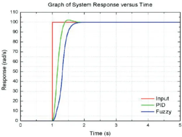
Figure 14 shows the system performance after the final tuning whereby all inputs and output were involved. PID controller yielded a low percentage of overshoot but had a faster overall rising and settling time. On the other hand, a reasonable transient response was produced from the fuzzy logic controller. The fuzzy controller was able to perform without overshoot although with the expense of a longer time, and suffered from long rising and settling time. Figure 14, 15 and 16 shows the different membership function for error, error integral and output after the final tuning. There are several modifications done to the initial membership function whereby each of the membership function was changed to a triangular membership function from the initial choice of the Gaussian and trapezoidal membership functions. Figure 17 shows the system response from the final tuning of the FLC.
ISSN: 2600 - 7495 IJEEAS, Vol. 1, No. 1, April 2018
International Journal of Electrical Engineering and Applied Sciences
14
M. S. M Aras et. al.
journal.utem.edu.my |ISSN 2600-7495 Fig. 14. MF for error after tuning.
Fig. 15. MF for rate of change of error after tuning.
Fig. 16. MF for output after tuning.
Fig. 17. Response from final tuning.
To further analyze the practicality and robustness of the fuzzy logic controller, the system was tested with square trajectories with a different duty cycle. 2 trajectories were tested which is square trajectory of 25% and 50% duty cycle, respectively. The results were displayed in Figure 18 and Figure 19, respectively.
TABLE 3:
COMPARISON OF CONTROLLER PERFORMANCE
From Table 3, it can be seen that PID had a slightly better transient response. However, it still suffered from the overshoot. The fuzzy controller was able to perform without overshoot. Overall, both controllers were able to yield results without any steady-state error.
It can also be seen that the fuzzy controller was able to provide a good tracking result with no overshoot. But, the fuzzy controller was inferior in the transient response. The fuzzy controller yielded a longer overall transient response. From the comparison of both trajectory inputs, fuzzy logic controller performed better when the duty cycle of the trajectory was increased. It can also be observed in Figure 19 and Figure 20 that the fuzzy logic controller performed better in the second rectangular simulation than the first simulation. This suggests that the fuzzy controller was able to adapt and performed better over time. Conversely, the PID controller performed similarly for each rectangular simulation. Hence, it can be concluded that the fuzzy controller is more adaptable in comparison to the PID controller.
Evaluation of Transient Response for Rotary Inverted Pendulum Positioning using Fuzzy Logic ControllerM. S. M Aras et. al.
Fig. 19. Square Trajectory Tracking (25% duty cycle).
Fig. 20. Square Trajectory Tracking (50% duty cycle). Lastly, the system was tested with a triangular trajectory. The result is presented in Figure 21. The PID controller was able to track the trajectory however at the expense of a longer time delay. It can also be seen that the fuzzy logic controller was able to provide a better tracking results with minimal steady state error. The fuzzy controller suffered a lag before tracking adequately when the triangular stimulus was provided. However, the tracking performance of the fuzzy controller improved over time yet maintaining a lower margin of tracking error. This showed that fuzzy controller is a better controller to be applied in non-linear systems.
Fig. 21. Triangular Trajectory Tracking.
V. Conclusion
This paper introduces the challenges of developing a practical yet robust controller to the rotary inverted pendulum. The main challenge lies in the immanent non-linear characteristics due to the under-actuated nature of the system which results in the difficulty to control it. Therefore, this project was embarked to propose a fuzzy logic controller to control the position of the pendulum. The presented results show the significance of fuzzy controller when applied to a non-linear system. The fuzzy controller showed adequate response when compared to the PID controller in terms of responding to rectangular and triangular stimulus. Hence, the trial and error tuning method was sufficient to provide a satisfactory performance of the modern controller. Although a satisfactory performance was obtained, the performance was not yet robust for the dynamic system of rotary inverted pendulum. However, the methodology applied in this project would serve as a guideline for future works on the controller design for this system.
Acknowledgements
We wish to express our gratitude to honorable University, Universiti Teknikal Malaysia Melaka (UTeM). Special appreciation and gratitude to the Faculty of Electrical Engineering, Centre of Research and Innovation Management (CRIM) and Ministry of Higher Education for supporting this research under FRGS/1/2015/TK04/FKE/02/F00257.
References
[1] A. A. Shojaei, M. F. Othman, R. Rahmani & M. R. Rani, A Hybrid Control Scheme for a Rotational Inverted Pendulum, UKSim 5th European Symposium on Computer Modeling and Simulation, pp. 83–87, 2011.
[2] L. B. Prasad, B. Tyagi & H. O. Gupta, Optimal control of nonlinear inverted pendulum dynamical system with disturbance input using PID controller & LQR, IEEE International Conference on Control System, Computing and Engineering, pp. 540–545, 2011.
[3] Masanori Yukitomo, Takashi Shigemasa, Yasushe Baba, Fumia Kojima, A Two Degrees of Freedom PID Control System, its Features and Applications, 5th Asian Control Conference, 2004. [4] Purtojo, R. Akmeliawati and Wahyudi, Two-parameter Compensator Design for Point-to-point (PTP) Positioning System Using Algebraic Method, The Second International Conference on Control, Instrumentation and Mechatronic Engineering (CIM09), Malacca, Malaysia, 2009.
[5] Mituhiko Araki and Hidefumi Taguchi, Two-Degree-of-Freedom PID Controllers, International Journal of Control, Automation, and Systems Vol. 1, No. 4, 2003.
[6] M Gopal, Digital Control and State Variable methods Conventional and Neural-Fuzzy Control System, 2nd edition, International Edition, Mc Graw Hill, ISBN 0-07-048302-7, printed in Singapore, 2004.
[7] Md. Akhtaruzzaman, Dr. Rini Akmeliawati and Teh Wai Yee, Modeling and Control of a Multi degree of Freedom Flexible Joint Manipulator, Second International Conference on Computer and Electrical Engineering (ICCEE `09), DUBAI, UAE, p. 249 – 254, 2009.
ISSN: 2600 - 7495 IJEEAS, Vol. 1, No. 1, April 2018
International Journal of Electrical Engineering and Applied Sciences
16
M. S. M Aras et. al.
journal.utem.edu.my |ISSN 2600-7495 [8] Mohd Shahrieel Mohd Aras, Shahrum Shah Abdullah, Adaptive
Simplified Fuzzy Logic Controller for Depth Control of Underwater Remotely Operated Vehicle, Indian Journal of Geo-Marine Science, Vol 44 (12), 1995-2007, 2015.
[9] Mohd Shahrieel Mohd Aras, Fadilah Abdul Azis, Shahrum Shah Abdullah, Lee Dai Cong, Lim Wee Teck, Fara Ashikin Ali, Muhammad Nur Othman, Study on the Effect of Shifting 'Zero' in Output Membership Function on Fuzzy Logic Controller of The ROV using Micro-Box Interfacing, Jurnal Terknologi, 74:9,119– 128, 2015.
[10] Mohd Aras, Mohd Shahrieel and Jaafar, Hazriq Izzuan and Anuar, Mohamed Kassim, Tuning Process of Single Input Fuzzy Logic Controller Based on Linear Control Surface Approximation Method for Depth Control of Underwater Remotely Operated Vehicle, Journal of Engineering and Applied Sciences, 8 (6). pp. 208-214. ISSN 1816-949X, 2013.
[11] Mohd Aras, Mohd Shahrieel and Abdul Rahman, Ahmad Fadzli Nizam, Analysis of an Improved Single Input Fuzzy Logic Controller Designed For Depth Control Using Microbox 2000/2000c Interfacing, International Review of Automatic Control, 6 (6). pp. 728-733. ISSN 1974-6059, 2013.
[12] Mohd Aras, Mohd Shahrieel and Mohd Shah, Hairol Nizam and Ab Rashid, Mohd Zamzuri, Robust Control Of Adaptive Single Input Fuzzy Logic Controller For Unmanned Underwater Vehicle, Journal of Theoretical and Applied Information Technology, 57 (3). pp. 372-379. ISSN 1992-8645, 2013.
[13] Mohd Aras, Mohd Shahrieel and Abdul Azis, Fadilah and Fara Ashikin , Ali and Syed Mohamad Shazali, Syed Abdul Hamid and Mohd Farriz , Md Basar, Performances Evaluation and Comparison of Two Algorithms for Fuzzy Logic Rice Cooking System (MATLAB Fuzzy Logic Toolbox and FuzzyTECH). IEEE Conference on Open Systems, Langkawi, Malaysia, 2011. [14] Mohd Aras, Mohd Shahrieel and Hairi, Mohd Hendra and Syed
Salim, Syed Najib and Wan Abdul razak, Intan Azmira, Comparison of Fuzzy Control Rules using MATLAB Toolbox and Simulink for DC Induction Motor-Speed Control, International Conference of Soft Computing and Pattern Recognition, Malacca, Malaysia, 2009.