Turin Networks Inc.
TransNav Management System
Documentation
Release TN4.2.x
Publication Date: October 2008
FCC Compliance
This equipment has been tested and found to comply with the limits for a Class A digital device, pursuant to Part 15 of the FCC Rules. This equipment generates, uses, and can radiate radio frequency energy and, if not installed and used in accordance with the installation instructions may cause harmful interference to radio communications.
Canadian Compliance
This Class A digital apparatus meets all requirements of the Canadian Interference-Causing Equipment Regulations. Cet appareil numérique de la classe A respects toutes les exigences du Règlement sur le matériel brouilleur du Canada.
Japanese Compliance
This is a Class A product based on the standard of the Voluntary Control Council for Interference by Information Technology Equipment (VCCI). If this equipment is used in a domestic environment, radio disturbance may occur, in which case, the user may be required to take corrective actions.
International Declaration of Conformity
We, Turin Networks, Inc. declare under our sole responsibility that the Traverse platform (models: Traverse 2000, Traverse 1600, and Traverse 600) to which this declaration relates, is in conformity with the following standards:
EMC Standards
EN55022 EN55024 CISPR-22
Safety Standards
EN60950 CSA 22.2 No. 60950, ASINZS 3260
IEC 60950 Third Edition. Compliant with all CB scheme member country deviations.
Following the provisions of the EMC Directive 89/336/EEC of the Council of the European Union.
Copyright © 2008 Turin Networks, Inc.
All rights reserved. This document contains proprietary and confidential information of Turin Networks, Inc., and may not be used, reproduced, or distributed except as authorized by Turin Networks. No part of this publication may be reproduced in any form or by any means or used to make any derivative work (such as translation, transformation or adaptation) without written permission from Turin Networks, Inc.
Turin Networks reserves the right to revise this publication and to make changes in content from time to time without obligation on the part of Turin Networks to provide notification of such revision or change. Turin Networks may make improvements or changes in the product(s) described in this manual at any time.
Turin Networks Trademarks
Turin Networks, the Turin Networks logo, Traverse, TraverseEdge, TransAccess, TransNav, and Creating The Broadband Edge are trademarks of Turin Networks, Inc. or its affiliates in the United States and other countries. All other trademarks, service marks, product names, or brand names mentioned in this document are the property of their respective owners.
Government Use
Use, duplication, or disclosure by the U.S. Government is subject to restrictions as set forth in FAR 12.212 (Commercial Computer Software-Restricted Rights) and DFAR 227.7202 (Rights in Technical Data and Computer Software), as applicable.
T
RANS
N
AV
P
RODUCT
O
VERVIEW
G
UIDE
Contents
About this Document . . . iii
Section 1 Overview and Features
Chapter 1
Overview . . . 1-1 Chapter 2
Network Management Features . . . 1-7 Chapter 3
User Interfaces . . . 1-13
Section 2 Management System Planning
Chapter 1
TransNav Management System Requirements . . . 2-1 Chapter 2
TransNav Management System Planning. . . 2-9 Chapter 3
IP Address Planning . . . 2-11 Chapter 4
Network Time Protocol (NTP) Sources . . . 2-23 Index. . . Index-1
Product Overview [TN4.2.x] Document Description
About this Document
Introduction This description contains the following documentation topics:
• Traverse System Product Documentation, page 1
• TraverseEdge System Product Documentation, page 1
• TransNav Management System Product Documentation, page 1
• Operations Documentation, page 1
• Information Mapping, page 1
• If You Need Help, page 1
• Calling for Repairs, page 1
Refer to “What’s New in the Documentation?” to review the new and changed features for this release.
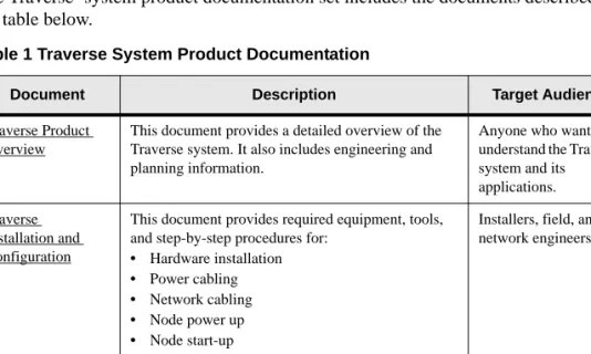
Traverse System Product Documentation
The Traverse®
system product documentation set includes the documents described in the table below.
Table 1 Traverse System Product Documentation
Document Description Target Audience
Traverse Product Overview
This document provides a detailed overview of the Traverse system. It also includes engineering and planning information.
Anyone who wants to understand the Traverse system and its applications. Traverse
Installation and Configuration
This document provides required equipment, tools, and step-by-step procedures for:
• Hardware installation
• Power cabling
• Network cabling
• Node power up
• Node start-up
Installers, field, and network engineers
Traverse Provisioning
This document provides step-by-step procedures for provisioning a network of Traverse nodes using the TransNav management system. See the TransNav Management System Product Documentation.
Network engineers, provisioning, and network operations center (NOC) personnel
TraverseEdge System Product Documentation
TraverseEdge System Product Documentation
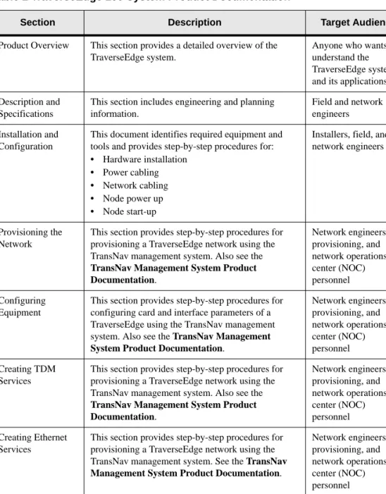
The TraverseEdge™ 100 User Guide includes the sections described in the table below.
Table 2 TraverseEdge 100 System Product Documentation
Section Description Target Audience
Product Overview This section provides a detailed overview of the TraverseEdge system.
Anyone who wants to understand the TraverseEdge system and its applications Description and
Specifications
This section includes engineering and planning information.
Field and network engineers Installation and
Configuration
This document identifies required equipment and tools and provides step-by-step procedures for:
• Hardware installation
• Power cabling
• Network cabling
• Node power up
• Node start-up
Installers, field, and network engineers
Provisioning the Network
This section provides step-by-step procedures for provisioning a TraverseEdge network using the TransNav management system. Also see the
TransNav Management System Product Documentation. Network engineers, provisioning, and network operations center (NOC) personnel Configuring Equipment
This section provides step-by-step procedures for configuring card and interface parameters of a TraverseEdge using the TransNav management system. Also see the TransNav Management System Product Documentation.
Network engineers, provisioning, and network operations center (NOC) personnel Creating TDM Services
This section provides step-by-step procedures for provisioning a TraverseEdge network using the TransNav management system. Also see the
TransNav Management System Product Documentation. Network engineers, provisioning, and network operations center (NOC) personnel Creating Ethernet Services
This section provides step-by-step procedures for provisioning a TraverseEdge network using the TransNav management system. See the TransNav Management System Product Documentation.
Network engineers, provisioning, and network operations center (NOC) personnel Appendices This section provides installation and provisioning
checklists, compliance information, and acronym descriptions.
Installers and anyone who wants reference information.
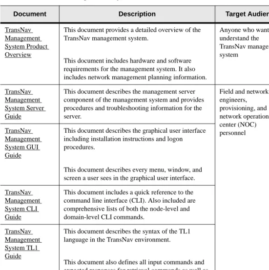
TransNav Management System Product Documentation TransNav Management System Product Documentation
The TransNav™ management system product documentation set includes the documents described in the table below.
Table 3 TransNav Management System Product Documentation
Document Description Target Audience
TransNav Management System Product Overview
This document provides a detailed overview of the TransNav management system.
This document includes hardware and software requirements for the management system. It also includes network management planning information.
Anyone who wants to understand the TransNav management system TransNav Management System Server Guide
This document describes the management server component of the management system and provides procedures and troubleshooting information for the server.
Field and network engineers, provisioning, and network operations center (NOC) personnel TransNav Management System GUI Guide
This document describes the graphical user interface including installation instructions and logon procedures.
This document describes every menu, window, and screen a user sees in the graphical user interface. TransNav
Management System CLI Guide
This document includes a quick reference to the command line interface (CLI). Also included are comprehensive lists of both the node-level and domain-level CLI commands.
TransNav Management System TL1 Guide
This document describes the syntax of the TL1 language in the TransNav environment.
This document also defines all input commands and expected responses for retrieval commands as well as autonomous messages that the system outputs due to internal system events.
Operations Documentation
Operations Documentation
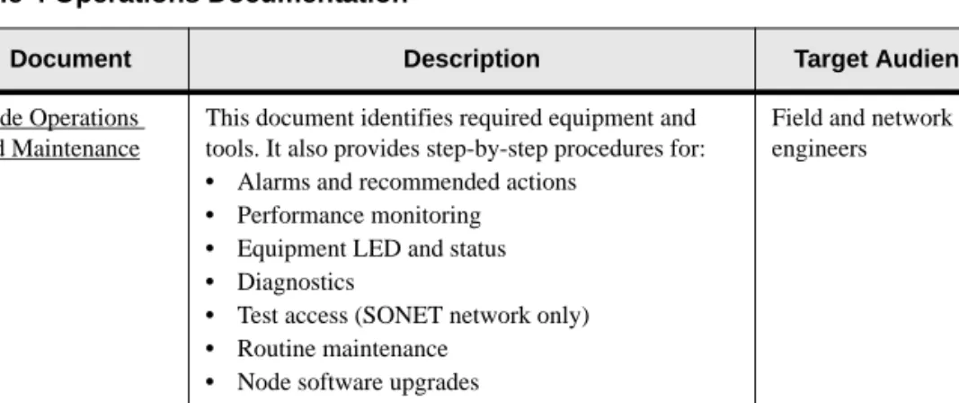
The document below provides operations and maintenance information for Turin’s TransNav managed products.
Information Mapping
Traverse, TransNav, and TraverseEdge 100 system documentation uses the Information Mapping format which presents information in small units or blocks. The beginning of an information block is identified by a subject label in the left margin; the end is identified by a horizontal line. Subject labels allow the reader to scan the document and find a specific subject. Its objective is to make information easy for the reader to access, use, and remember.
Each procedure lists the equipment and tools and provides step-by-step instructions required to perform each task. Graphics are integrated into the procedures whenever possible.
If You Need Help
If you need assistance while working with Traverse products, contact the Turin Networks Technical Assistance Center (TAC):
• Inside the U.S., toll-free: 1-866-TURINET (1-866-887-4638) • Outside the U.S.: 916-348-2105
• Online: www.turinnetworks.com/html/support_overview.htm
TAC is available 6:00AM to 6:00PM Pacific Time, Monday through Friday (business hours). When the TAC is closed, emergency service only is available on a callback basis. E-mail support (24-hour response) is also available through:
Calling for Repairs
If repair is necessary, call the Turin Repair Facility at 1-866-TURINET (866-887-4638) for a Return Material Authorization (RMA) number before sending the unit. The RMA number must be prominently displayed on all equipment cartons. The Repair Facility is open from 6:00AM to 6:00PM Pacific Time, Monday through Friday.
When calling from outside the United States, use the appropriate international access code, and then call 916-348-2105 to contact the Repair Facility.
Table 4 Operations Documentation
Document Description Target Audience
Node Operations and Maintenance
This document identifies required equipment and tools. It also provides step-by-step procedures for:
• Alarms and recommended actions
• Performance monitoring
• Equipment LED and status
• Diagnostics
• Test access (SONET network only)
• Routine maintenance
• Node software upgrades
• Node hardware upgrades
Field and network engineers
Calling for Repairs
When shipping equipment for repair, follow these steps:
1. Pack the unit securely.
2. Enclose a note describing the exact problem.
3. Enclose a copy of the invoice that verifies the warranty status.
4. Ship the unit PREPAID to the following address: Turin Networks, Inc.
Turin Repair Facility Attn: RMA # ________ 1415 North McDowell Blvd. Petaluma, CA 94954 USA
S
ECTION
1 O
VERVIEW
AND
F
EATURES
SECTION 1MANAGEMENT SYSTEM OVERVIEW
MANAGEMENT SYSTEM OVERVIEW
Contents
Chapter 1 Overview
What Is the TransNav Management System?. . . 1-1 TransNav Software Architecture . . . 1-1 Client Workstation Application. . . 1-2 Management Server Application . . . 1-2 Node Agent Application. . . 1-3 TransNav Management System Features. . . 1-3 Interoperability with Third-party Management Systems . . . 1-4 Autodiscovery and Pre-provisioning . . . 1-4 Simultaneous Users . . . 1-4 Scalability . . . 1-4 Reliability, Availability, and Serviceability (RAS) . . . 1-5 Chapter 2
Network Management Features
Fault and Event Management . . . 1-7 Alarm Data. . . 1-7 Data Sequence . . . 1-7 Flexible Filtering . . . 1-8 Flexible Scoping . . . 1-8 Sorting . . . 1-8 Clearing Alarms . . . 1-8 Configuration Management . . . 1-8 Equipment Configuration. . . 1-8 Pre-provisioning . . . 1-9 Service Provisioning . . . 1-9 Secondary Server Support . . . 1-9 Accounting Management. . . 1-10 Performance Management . . . 1-10 Role-based Access Control. . . 1-10 Domain Users . . . 1-10 Node Users . . . 1-10 Node Administration . . . 1-10 System Log Collection and Storage . . . 1-11 Report Generation. . . 1-11 General Reports . . . 1-11
TransNav Product Overview Guide, Section 1 Overview and Features
Chapter 3 User Interfaces
Access to User Interfaces . . . 1-13 Graphical User Interfaces . . . 1-14 Map View . . . 1-14 Shelf View . . . 1-15 Command Line Interface . . . 1-16 Domain Level CLI . . . 1-17 Node Level CLI . . . 1-17 TL1 Interface . . . 1-17
List of Figures
Figure 1-1 TransNav Software Architecture . . . 1-2
Figure 1-2 Map View . . . 1-14
Figure 1-3 Shelf View . . . 1-16
List of Tables
SECTION 1OVERVIEW AND FEATURES
Chapter 1
Overview
Introduction This chapter describes the TransNav management system:
• What Is the TransNav Management System?, page 1-1
• TransNav Software Architecture, page 1-1
• Client Workstation Application, page 1-2
• Management Server Application, page 1-2
• Node Agent Application, page 1-3
• TransNav Management System Features, page 1-3
What Is the TransNav Management System?
The TransNav management system is an advanced element and subnetwork
management system designed for comprehensive management of the Traverse network consisting of Traverse, TraverseEdge, and TransAccess products. The Java™-based software smoothly integrates into existing automated and manual operations support system (OSS) infrastructure.
The multi-level management architecture applies the latest distributed and evolvable technologies. These features enable you to create and deploy profitable new services, as well as transition gracefully to a more dynamic and data-centric, multi-service optical transport network.
The TransNav management system consists of an integrated set of software
components that reside on the server(s), the client workstations, and individual nodes.
• Client Workstation Application, page 1-2. Provides the user interface for
managing the network. The management system supports a graphical user interface (GUI), a command line interface (CLI), and a TL1 interface.
• Management Server Application, page 1-2. Communicates with the nodes and
the servers, as well as provides classical element management FCAPS
functionality (fault, configuration, accounting, performance, and security), policy management, reporting, and system administration.
• Node Agent Application, page 1-3. Resides on the control card and maintains a
persistent database of management information for specific nodes. It also controls the flow of information between the management server and specific nodes.
TransNav Product Overview Guide, Section 1: Overview and Features
Client Workstation Application
implementation of Java Management Extensions (JMX) to provide an efficient client-server architecture.
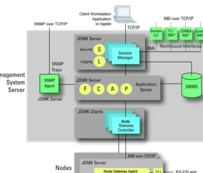
Figure 1-1 TransNav Software Architecture
All communication between nodes and the server or between the client application and the server uses the Java Remote Method Invocation (RMI) system over TCP/IP. The server also uses RMI internally between the JDMK servers and JDMK clients. Information flows southbound – from the user on the client workstation, to the Session Manager, to the application server, to the Traverse Node Gateway Client inside the management server, and finally down to the Traverse Node Gateway Agent embedded in the node – via RMI over TCP/IP.
Client Workstation Application
The client workstation application provides the user interface for managing the network. The TransNav management system supports GUI, CLI, and TL1 interfaces. See Figure 1-1 TransNav Software Architecture for a graphical representation of the client workstation application.
The client workstation application communicates with the session manager on the management server. Download the GUI application from the management server, or simply telnet to the management server, to access the CLI or TL1.
Management Server Application
The management server application communicates with nodes and provides classical element management FCAPS functionality (fault, configuration, accounting,
performance, and security), as well as policy management, reporting, and system administration. See Figure 1-1 TransNav Software Architecture for a graphical representation of the management server application.
Chapter 1 Overview
TransNav Management System Features
Security management, logging, and external interfaces to upstream applications are all implemented in the upper level session management component on the management server. These functions are implemented as a JDMK server and are responsible for servicing both the GUI client applet and the northbound interfaces. Enhanced security is achieved using Functional Groups to provide RBAC (Role-based Access Control) functionality.
A separate SMNP agent, also implemented as a JDMK server, supports SNMP traps (fault management) for simplified version control. The SNMP agent works with the fault management application card.
The agent on the node passes node-level data to the management server via RMI over TCP/IP. On the management server, the Node Gateway Controller receives the information and pre-processes it. The Node Gateway Controller then passes the pre-processed information to the management functions within the application server. The application server is responsible for persistence at the server side and, to this end, manages the entire interface with the underlying SQL database.
Each TransNav management system supports up to eight servers; one server is designated as the Primary server, the remaining servers are designated as Secondary servers. The Primary server actively manages the network. The Secondary servers passively view the network but cannot perform any management operations that would change the state of the network. Any Secondary server can be promoted to the Primary server role in case of failure or maintenance. The switch in server roles requires some degree of user intervention.
Node Agent Application
Each node has a redundant control card with a persistent relational database management system that records provisioning, alarm, maintenance, and diagnostic information for the node. See Figure 1-1 TransNav Software Architecture for a graphical representation of the node agent application.
Each control card uses Java agents (M-Beans [management beans]) to communicate with Java applications on the management server and synchronize data between the server and the nodes it manages.
TransNav Management System Features
The TransNav management system provides comprehensive management for both the nodes and for the connections between nodes through the Intelligent Control Plane. This specifically includes efficient integration of management plane and control plane functions, and policy-based management.
The TransNav management system features include:
• Interoperability with Third-party Management Systems, page 1-4
• Autodiscovery and Pre-provisioning, page 1-4
• Simultaneous Users, page 1-4
• Scalability, page 1-4
TransNav Product Overview Guide, Section 1: Overview and Features
Interoperability with Third-party Management Systems
Interoperability with
Third-party Management Systems
The TransNav management system supports other telecommunications management network layer functions at the network management layer, the service management layer, and the business management layer through a variety of northbound interfaces. The management system provides options to support the following interfaces:
• Forwarding of SNMP traps to SNMP network management systems for integrated higher-layer fault management
• Domain-level and node-level CLI via scripts
• TL1 alarm and performance management forwarding from the management server • TL1 equipment and protection group configuration and test access
Autodiscovery and Pre-provi-sioning
Each node uses a process called autodiscovery to learn the addresses of all equipment in its control plane domain. Commission the node using the CLI and enter the host name or IP address of the gateway node(s). The management system then discovers and manages all the nodes in the domain without requiring any other preprovisioned information.
The TransNav management system supports preprovisioning which allows provisioning functions independent of service activation. The effectiveness of
preprovisioning depends upon effective traffic engineering to ensure network capacity is available upon activation. Upon installation, a node is discovered automatically and the management server forwards the preprovisioned information to the node.
Simultaneous Users
The number of simultaneous users of user sessions is configurable on the server (MaxNoOfUserSessions). The default is 20 simultaneous users. The management system does not restrict the number of simultaneous users either by software licensing or system configuration parameters. Customer usage patterns may allow more simultaneous users with reasonable response time than specified.
One GUI session, one CLI session, or one TL1 session counts as a simultaneous user. Up to 10 simultaneous users can log into a node-level CLI session.
Scalability Turin works with customers to specify configurations to support the scalability required. The TransNav management system supports:
• 1 to 8 TransNav servers. One server is designated the Primary server, the remaining servers are Secondary servers.
• Up to 200 Traverse nodes and simultaneous users for servers, based on specific user behaviors, by:
– Selecting a multi-processor server with the potential capacity to support the estimated maximum requirements, and the addition of CPUs, memory, and disk capacity as needed.
– Distributing various components of the management system over multiple servers.
Chapter 1 Overview
Reliability, Availability, and Serviceability (RAS)
Reliability, Availability, and
Serviceability (RAS)
Turin works closely with customers to configure hardware and software to achieve desired levels of high availability for their Sun Solaris server-based TransNav system deployments. This includes supporting secondary network operation centers for disaster recovery. Our goal is to achieve exceptional service reliability and availability in a cost-effective manner.
TransNav Product Overview Guide, Section 1: Overview and Features
SECTION 1OVERVIEW AND FEATURES
Chapter 2
Network Management Features
Introduction The TransNav management system provides classical element management
functionality (FCAPS—fault, configuration, accounting, performance, and security), plus policy management, reporting, and system administration.
• Fault and Event Management, page 1-7
• Configuration Management, page 1-8
• Secondary Server Support, page 1-9
• Accounting Management, page 1-10
• Performance Management, page 1-10
• Role-based Access Control, page 1-10
• Node Administration, page 1-10
• System Log Collection and Storage, page 1-11
• Report Generation, page 1-11
Fault and Event Management
The TransNav management system graphical user interface (GUI) enables each technician to open multiple Alarm windows. The number of windows is limited only by effective use of the workstation’s screen area and the client workstation system resources, such as memory and CPU load.
If technicians have their nodes grouped, clicking a node group in the navigation tree or clicking a node group map displays only the alarms associated with that node group. This includes nodes and node groups within the parent-level node group.
In the GUI, windows and dialog boxes have the following characteristics:
Alarm Data
The system provides a count of the number of outstanding alarms by severity level. This information is available at a network level as well as for each individual node.
Data Sequence
TransNav Product Overview Guide, Section 1: Overview and Features
Configuration Management
Flexible Filtering
The user can determine what data appears in the selected fields for each separate Alarm window.
Flexible Scoping
The user can determine which nodes and equipment appear in the selected fields for each separate Alarm window.
Sorting
When a column heading (e.g., “severity”) is selected, the Alarm window is sorted by that category.
Clearing Alarms
Only a node clears alarms. Alarms received by the management system are automatically marked as cleared and added to the display. The user can also set the retention duration of cleared alarm messages in the server alarm database and the alarm display.
Graphical buttons and a context menu provide the following options: • Acknowledge the alarm.
• Select a detailed alarm view that allows the user to view alarm details in addition to adding comments.
• Set filters that allow the user to include or exclude alarms from specific sources from being displayed in the Alarm window.
• Open a new Alarm window.
Configuration Management
Use the TransNav management system for all configuration management requirements:
• Equipment Configuration, page 1-8
• Pre-provisioning, page 1-9
• Service Provisioning, page 1-9
• Secondary Server Support, page 1-9
• Report Generation, page 1-11
Equipment Configuration
After a node is installed and activated, it discovers its specific components and forwards that information to the management system, The system, in turn, populates its databases and builds the graphical representation of the equipment. The Intelligent Control Plane automatically discovers the network and forwards that information to the management plane which creates the network topology map.
Use node-level CLI for initial system commissioning. For detailed information, see the Traverse Installation and Commissioning Guide, Section 11—Node Start-up and
Commissioning Procedures, Chapter 1—“Node Start-up and Commissioning,”
page 11-1.
The TransNav management system supports Telcordia CLEI™
(Common Language®
Equipment Identifier) codes per GR-485-CORE. These are encoded on individual cards.
Chapter 2 Network Management Features
Secondary Server Support
Pre-provisioning The TransNav management system supports complete preprovisioning of all nodes. Preprovisioning facilitates rapid turn-up of new nodes and node expansions as well as support for planning and equipment capital control. Preprovisioning of customer services enables the service provider to efficiently schedule provisioning work independent of service activation.
The management system stores the parameters of the service request and sends them to the Intelligent Control Plane upon activation. If the management system is unable to complete activation, it provides appropriate alarms including insight into the nature of the inability to complete provisioning and activation of the service. The effectiveness of preprovisioning depends upon effective traffic engineering to ensure that network capacity is available upon activation.
Service Provisioning
The TransNav management system provides end-to-end provisioning of services and requires minimal input from the user. Alternatively, the user can set the constraints (each hop and time slot) of a service. You can provision a service using any of the following methods:
• Graphical user interface
• Script language (typical for batch provisioning) • Domain-level CLI interface
Secondary Server Support
The Traverse management system supports one Primary server and up to seven Secondary servers in the network. The Primary server actively manages the network, while the Secondary servers passively view the network but do not perform any management operations that would change the network. If the Primary server fails or is scheduled for maintenance, any Secondary server can be manually changed to take the Primary server role.
Critical information on the Secondary servers is synchronized with the network elements automatically in real time. This includes current provisioning, service state, alarm and event information from the Traverse nodes. To synchronize PM data, Domain user login profiles, user references and roles, customer records, alarm acknowledgement and annotations, reports, report templates and schedules, the Primary server database must be exported and then imported to the Secondary server database. Depending on the network size, the import process takes between one and five minutes.
Manual synchronization should be performed on a Secondary server database before it is promoted to a Primary server role. For detailed information on promoting a
Secondary server, see the TransNav Management System Server Guide,
Section 2—Management Server Procedures, Chapter 3—“Server Administration Procedures,” or the TransNav Management System CLI Guide, Chapter 2—“CLI Quick Reference.”
TransNav Product Overview Guide, Section 1: Overview and Features
Accounting Management
Accounting Management
Accounting data for all services is based primarily on performance management data and transmitted from the nodes to the management system.
Using this data, the service provider can track service levels and ensure that traffic complies with service level agreements (SLAs). SLA monitoring enables the service provider to create a billing opportunity and to charge a premium for the guaranteed level of service.
Performance Management
Nodes collect performance management data and forward it to the Primary management server to store in the database. The data is processed in two ways: • The service provider’s management system administrator can set threshold
crossing alert limits. The threshold crossing alert appears as an event on the GUI Events tab.
• The TransNav management system on the Primary server provides basic reports. The data can be exported for analysis and graphical presentation by applications such as Microsoft®
Excel.
Role-based Access Control
Security management enables the network administrator to create and manage user accounts with specific access privileges.
Access control on the management system is through a combination of functional
groups and access groups for domain users, and through access groups for node users.
Domain Users
A domain user can only belong to one functional group at a time. With the exception of
administrators, functional groups are user-defined combinations of pre-defined access
groups and specific nodes. Domain users in a functional group who have Administrator roles can access all of the system resources, including user management. They assign access privileges of other domain users to a set of system features (access groups) and resources (nodes) with user-defined functional groups. Security applies to both the GUI and the CLI. For more information on domain security, see the TransNav Management System GUI Guide, Section 2—Administrative Tasks, Chapter 1—“Managing Server Security,” page 2-1.
Node Users
The management system has several pre-defined access groups for node users. Any node user can be in one or more access groups. Within the access groups, access is cumulative; a user who is in two access groups has the privileges of both access groups. See the TransNav Management System GUI Guide, Section 2—Administrative Tasks, Chapter 2—“Managing Node Security,” page 2-11 for more information on node security.
Node
Administration
The TransNav management system provides the following capabilities to support efficient remote administration of nodes:
• Software management and administration
The GUI interface allows users to view an entire network, a group of nodes, or a specific node. Groups of nodes can be set up in a hierarchical fashion, and can be associated with specific geographical maps that coincide with each node group.
Chapter 2 Network Management Features
Report Generation
• Synchronization of the node and management system databases
The management system database is a superset of each node’s database and eliminates the need for remote backup and restore of the node itself. The database on each node is synchronized with the management server database, based on user-defined policies.
• Equipment alarm and event history analysis
• Remote restore of the database on the node for disaster recovery in the event of:
– A failure of both control cards or a major central office (CO) catastrophe.
– A major, unpredictable service provider network failure that creates uncertainty about the general state of node databases.
The TransNav management system has a local persistent database on the
fault-protected control cards that protects against a single control card failure. A major advantage of the Intelligent Control Plane automatic mesh service setup and restoration mechanism is to maintain service connectivity.
System Log Collection and Storage
The TransNav management system collects a broad array of information that is stored in the server database for reporting and analysis.
The following list represents data that can be extracted from the server database: • All user actions from the domain-level GUI or CLI or through the node-level CLI. • Alarm and event history including performance management threshold crossing
alerts:
– Equipment configuration history
– Node equipment alarm log • Security logs:
– User list denoting each user’s profile
– Sign-on/sign-off log
– Failed log-on attempts • Performance management data
Report Generation
All reports can be printed or exported as text-formatted comma delimited files.
General Reports
The TransNav management system allows a set of pre-defined reports to be either scheduled or executed on demand. These reports encompass such functions as: • Equipment inventory
• Historical alarms • Historical events
• Performance monitoring and management • Resource availability
• Service availability • Domain service
TransNav Product Overview Guide, Section 1: Overview and Features
Report Generation
Data Set Snapshots
The TransNav management system also provides a simple form of reporting that produces a file based on a set of information that is currently displayed in the GUI. For example, the GUI displays active alarms in a dialog box. The set of active alarms is a data set; the windowing capability of the GUI presents as much of this data set as possible in the display’s dialog box, allowing the user to scroll to view more of the data set. The management system allows the user to print, or save to a file, any data that the system can display in a dialog box. (Note: This is different from the “screen capture” function of the client workstation’s operating system that captures only the data set information visible in the dialog box.)
SECTION 1OVERVIEW AND FEATURES
Chapter 3
User Interfaces
Introduction The TransNav management system supports the following user interfaces:
• Access to User Interfaces, page 1-13
• Graphical User Interfaces, page 1-14
• Command Line Interface, page 1-16
• TL1 Interface, page 1-17
Access to User Interfaces
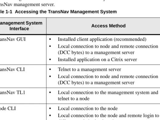
The following table lists the different access methods you can use to connect to a TransNav management server.
Table 1-1 Accessing the TransNav Management System Management System
Interface Access Method
TransNav GUI • Installed client application (recommended) • Local connection to node and remote connection
(DCC bytes) to a management server • Installed application on a Citrix server TransNav CLI • Telnet to a management server
• Local connection to node and remote connection (DCC bytes) to a management server
TransNav TL1 • Local connection to the management system and telnet to a node
Node CLI • Local connection to the node
• Local connection to the node and remote login to a different node in the domain
Node TL1 • Telnet to the management system and connect to a node
TransNav Product Overview Guide, Section 1: Overview and Features
Graphical User Interfaces
Graphical User Interfaces
The GUI supports domain-level operators and administrators who are located in a network operations center or in a remote location. There is no GUI at the node level. The GUI allows domain-level personnel to perform a wide range of provisioning and monitoring tasks for a single node, groups of nodes, or a network of nodes attached to a specific server. Users can only see those nodes to which they have security access rights.
There are two main views in the GUI:
• Map View, page 1-14
• Shelf View, page 1-15
See the TransNav Management System GUI Guide for detailed descriptions of the GUI. See the TransNav Management System Server Guide for information on saving background images.
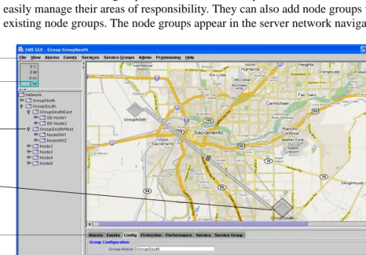
Map View Map View displays all of the node groups and discovered nodes for a server when you first start the GUI from that server. From Map View, you can see and manage all the nodes, node groups, links between the nodes, and network services. The graphic area displays a background image (usually a map of physical locations of the nodes) and icons representing the nodes. This initial background image is the Network Map view. Each node group can have a different background image associated with it; this is the Group Map.
Each domain user can group the nodes to which they have access in order to more easily manage their areas of responsibility. They can also add node groups within existing node groups. The node groups appear in the server network navigation tree.
Figure 1-2 Map View
The menu bar is context-sensitive. Commands display as available (highlighted) or
Menu bar Currently selected object Context-sensitive tabs Alarm summary tree Network navigation tree
Chapter 3 User Interfaces
Shelf View
summary tree gives you visibility at a glance to network alarms. If you select a node group, only alarms associated with that node group display.
The network navigation tree shows you the node groups and node networks attached to the server in an outline format in alphanumeric order. Node groups display first, then nodes. In Map View, clicking a node group or a node displays the node group or node name on the top and bottom bars of the window. To view the nodes in a node group, double-click the Group icon in Map View or expand the node group in the navigation tree. In Shelf View, right-clicking a node in the navigation tree or double-clicking the node in Map View to display a graphical representation of the node and related information; you can see which object (card or port) you have selected by the white rectangle around the object and the name that displays on the top and bottom bars of the window.
The context-sensitive tabs provide server, node group, or node information on alarms, events, configuration information, protection, services, and service groups.
Double-click a node group to display the node groups and nodes associated with it. Click a node to display node-specific information. Click anywhere on the map to display network information specific to the server.
Shelf View Shelf View displays all of the cards in a node and their associated ports. You can navigate to Shelf View in the following ways:
• Click the node in Map View, then select Show Shelf View from the View menu. • Double-click the node in Map View.
• Right-click a node in Map View and select Show Shelf View.
TransNav Product Overview Guide, Section 1: Overview and Features
Command Line Interface
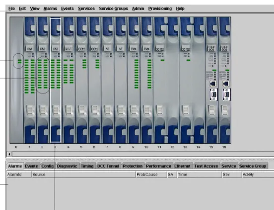
Figure 1-3 Shelf View
The menu bar is context-sensitive. Commands are displayed as available (highlighted) or unavailable (grayed out), depending on the selected object.
You can see which object you have selected by the white rectangle around the object in the graphic and the name displayed on the top and bottom bars of the window.
Context-sensitive tabs (in the bottom half of the screen) provide information on alarms, events, configuration information, protection, and services. In Shelf View, these tabs provide single node, card, or port information. Click a card to display card-specific information. Click a port to display port-specific information. Click an external clock to display external clock timing information.
A shortcut menu also exists for Shelf View. For more information, see TransNav Management System GUI Guide, Section 1—Installation and Overview, Chapter 4—“Graphical User Interface General Description,” page 1-34.
Command Line Interface
You can also access the TransNav management system using a command line interface (CLI). The CLI has these features:
• Command line editing: Use backspace and cursor keys to edit the current line and to call up previous lines for re-editing and re-submission.
• Hierarchical command modes: Organization of commands into modes with increasingly narrow problem domain scope.
• Context-sensitive help: Request a list of commands for the current context and
Currently selected object Menu bar BITS clock Context-sensitive tab screen Port LED status OR Alarm indicators
Chapter 3 User Interfaces
TL1 Interface
• Command completion: Enter a command or argument’s left-most substring and view a list of possible allowable completions. Abbreviate any command or argument to its left-most unique substring (for many commands, one character). • Context-sensitive prompt: The prompt for each command displays the current
command mode.
You can access a single node or a network of nodes using the CLI.
See the TransNav Management System CLI Guide for detailed information on the command line interface.
Domain Level CLI
Use domain-level commands from the TransNav management server to perform network commissioning, provisioning, synchronizing, and monitoring tasks. Domain-level commands affect multiple nodes in a network and include: • Setting the gateway node
• Configuring network links
• Creating performance monitoring templates and alarm profiles • Creating protection rings and services
• Generating reports
Accessing the domain-level CLI also gives you access to the node-level CLI through the node command.
Node Level CLI Use node-level CLI commands to perform commissioning, provisioning, or monitoring tasks on any node on the network. Node-level commands affect only one node in the network.
TL1 Interface The TransNav management system supports a TL1 interface to the management servers and to individual nodes. Currently, the TransNav management system supports a subset of TL1 commands.
Turin supports these node and network management tasks through the TL1 interface: • Fault and performance management (including test access and report generation) • Equipment configuration and management
• Protection group configuration and management • Security management
For information on TL1 and how to use the TL1 interface, see the TransNav Management System TL1 Guide.
TransNav Product Overview Guide, Section 1: Overview and Features
S
ECTION
2 M
ANAGEMENT
S
YSTEM
P
LANNING
SECTION 2MANAGEMENT SYSTEM PLANNING
Contents
Chapter 1
TransNav Management System Requirements
Management System Deployment . . . 2-2 TransNav Network Management . . . 2-2 Intelligent Control Plane . . . 2-2 Control Plane Domain . . . 2-3 Management Gateway Nodes. . . 2-3 Sun Solaris Platform for TransNav Management Server . . . 2-3 Windows Platform for TransNav Management Server . . . 2-5 TransNav GUI Application . . . 2-6 Chapter 2
TransNav Management System Planning
Recommended Procedure to Create a Network . . . 2-7 Chapter 3
IP Address Planning
IP Addresses in a TransNav Network . . . 2-9 IP Addressing Guidelines . . . 2-11
IP Networks and Proxy ARP . . . 2-11 In-Band Management with Static Routes . . . 2-11 Out-of-Band Management with Static Routes . . . 2-12 Out-of-Band Management with no DCC Connectivity . . . 2-12 TraverseEdge 50 and TransAccess Mux . . . 2-12 Quality of Service . . . 2-13 Proxy ARP . . . 2-14 In-Band Management with Static Routes . . . 2-15 In-Band Management with Router and Static Routes . . . 2-16 In-Band Management of CPEs Over EOP Links . . . 2-17 Out-of-Band Management with Static Routes. . . 2-19 Chapter 4
Network Time Protocol (NTP) Sources
NTP Sources in a Traverse Network . . . 2-21 Daylight Saving Time . . . 2-21 NTP Sources on a Ring Topology . . . 2-22 NTP Sources on a Linear Chain Topology . . . 2-22
TransNav Product Overview Guide, Section 2 Management System Planning
Figure 2-2 IP Quality of Service . . . 2-13
Figure 2-3 Traverse Node Enabled as a Proxy ARP Server. . . 2-14
Figure 2-4 TransNav Management System In-Band Management . . . 2-15
Figure 2-5 In-Band Management with Router and Static Routes . . . 2-16
Figure 2-6 In-Band Management of CPEs Over EOP Links . . . 2-17
Figure 2-7 Connecting CPEs through EOP Links . . . 2-18
Figure 2-8 TransNav Management System Out-of-Band Management . . . 2-19
Figure 2-9 NTP Sources on a Ring Topology . . . 2-22
Figure 2-10 NTP Sources on a Linear Chain Topology . . . 2-22
List of Tables
Table 2-1 Sun Solaris Requirements, TransNav Management Server . . . 2-3
Table 2-2 Windows Requirements, TransNav Management Server . . . 2-5
Table 2-3 TransNav GUI Application Requirements . . . 2-6
Table 2-4 Network Configuration Procedure and References . . . 2-7
SECTION 2MANAGEMENT SYSTEM PLANNING
Chapter 1
TransNav Management System Requirements
Introduction The TransNav management system software package contains both server and client workstation applications. The server functions communicate with the nodes and maintain a database of topology, configuration, fault, and performance data for all nodes in the network. The client workstation application provides the user interface for managing the network.
Use the requirements listed in the following sections to help you determine the management system requirements for your network.
• Management System Deployment, page 2-2
• TransNav Network Management, page 2-2
• Sun Solaris Platform for TransNav Management Server, page 2-3
• Windows Platform for TransNav Management Server, page 2-5
TransNav Product Overview Guide, Section 2: Management System Planning
Management System Deployment
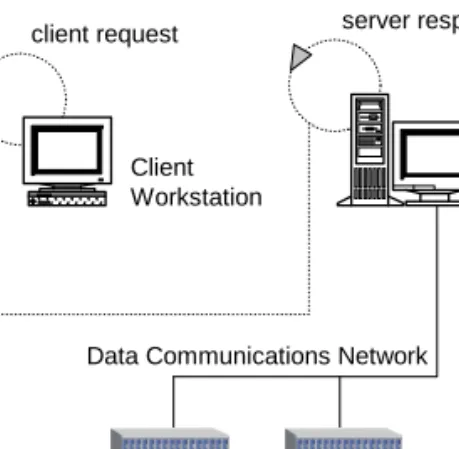
Management System Deployment
The TransNav management system software package contains server applications, client workstation applications, and agent applications that reside on the node.
Figure 2-1 Management System Deployment
Each TransNav management system supports up to eight servers; one server is designated as the Primary server, the remaining servers are designated as Secondary servers. The Primary server actively manages the network. The Secondary servers passively view the network but cannot perform any management operations that would change the state of the network. Any Secondary server can be promoted to the Primary server role in case of failure or maintenance. The switch in server roles requires some degree of user intervention.
The server applications communicate with the nodes and maintain a database of topology, configuration, fault, and performance data for all nodes. The client
workstation application provides the user interface for managing the network (GUI or CLI). The agent application resides on the node control card and maintains a persistent database of management information for the node. It also controls the flow of
information between the management server and the node itself.
TransNav Network Management
In addition to the management system applications, the TransNav management system uses the following Traverse software components:
Intelligent Control Plane
An Intelligent Control Plane is a logical set of connections between TransNav-managed network elements through which those network elements exchange control and management information. This control and management information can be carried either in-band or out-of-band.
• See Chapter 3—“IP Address Planning,” Quality of Service, page 2-13 for an example and description of IP quality of service routing protocol.
• See Chapter 3—“IP Address Planning,” Proxy ARP, page 2-14 for information o using the proxy address resolution protocol.
• See Chapter 3—“IP Address Planning,” In-Band Management with Static Routes, page 2-15 for an example and a detailed description.
Management System Server Host client request server response
Data Communications Network Client
Workstation
Chapter 1 TransNav Management System Requirements
Sun Solaris Platform for TransNav Management Server
Control Plane Domain
A control plane domain is a set of nodes completely interconnected by the intelligent control plane. One TransNav management system can manage up to 200 nodes in a single control plane domain.
Domain management includes tasks such as: • Setting the gateway node
• Configuring network links
• Creating performance monitoring templates and alarm profiles • Creating protection rings and services
• Generating reports
Management Gateway Nodes
The TransNav management server connects to nodes over the service provider’s TCP/IP data communications network. The management system accesses a network through one or more nodes that are designated as management gateway nodes (MGN). For in-band management, only one node is connected to the management server. Therefore, there is one MGN in a network that is managed in-band.
For out-of-band management, each node is connected to the management server either directly or through a router. Each node is considered a MGN.
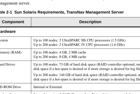
Sun Solaris Platform for TransNav Management Server
This table lists the minimum requirements for a Sun Solaris system TransNav management server.
Table 2-1 Sun Solaris Requirements, TransNav Management Server
Component Description
Hardware
System Up to 100 nodes: 2 UltraSPARC IIIi CPU processors (1.5 GHz) Up to 200 nodes: 2 UltraSPARC IV CPU processors (1.6 GHz) Memory (RAM) Up to 100 nodes: 4 GB, 2 MB cache
Up to 200 nodes: 8 GB, 4 MB cache
Hard Drives Up to 100 nodes: 73 GB of hard disk space (RAID controller optional; more disk space if a hot-spare is desired or if more storage is desired for log files) Up to 200 nodes: 146 GB of hard disk space (RAID controller optional; more disk space if a hot-spare is desired or if more storage is desired for log files) CD-ROM Drive Internal or External
Backup System Internal is optional; SAN (Storage Area Network) is recommended Network Two 10/100Base-T Ethernet cards. One card connects to the Data
Communications Network (DCN), and the other card connects to the Local Area Network (LAN) connecting the client workstations.
TransNav Product Overview Guide, Section 2: Management System Planning
Sun Solaris Platform for TransNav Management Server
Operating Environment
Sun Solaris 8, 9, or 10
Solaris 8 recommended patch cluster: Generic_108528-15 or later (July 29, 2002) (Note: For pre-TN3.1 releases only.)
Solaris 9 recommended patch cluster: date stamp of July 7, 2004 Bash shell
Management System Software
Obtain the latest version of the TransNav management system software in the Software Downloads section on the Turin Infocenter. Access the Infocenter at
www.turinnetworks.com. User registration is required. Contact your Turin Sales Support group.
PDF Viewer To view product documentation:
Adobe® Acrobat® Reader® 7.0 or 8.0 for Windows and 7.0.8 for Solaris.
Distributed on the documentation CD or download the application for free from Adobe’s site at: www.adobe.com/.
Table 2-1 Sun Solaris Requirements, TransNav Management Server (continued)
Chapter 1 TransNav Management System Requirements
Windows Platform for TransNav Management Server
Windows Platform for TransNav Management Server
This table lists the minimum requirements for a Windows platform TransNav management server.
Table 2-2 Windows Requirements, TransNav Management Server
Component Description
Hardware
System Up to 100 nodes: PowerEdge1850, 3.0 GHz Up to 200 nodes: PowerEdge6850, 3.6 GHz Memory (RAM) Up to 100 nodes: 4 GB, 2 MB cache
Up to 200 nodes: 8 GB, 4 MB cache Hard Drives Up to 100 nodes: 73 GB of hard disk space
Up to 200 nodes: 146 GB of hard disk space CD-ROM Drive Internal or External
Monitor Server only: High resolution 15-inch (1024 x 768) Server and client: High resolution 21-inch (1280 x 1024)
Disk Backup System Required if unable to back up TransNav database to server on the network. Network One or two 10/100BaseT Ethernet cards. One Ethernet Network Interface
Card (NIC) connects to the Data Communications Network (DCN). The second optional Ethernet NIC connects to the Local Area Network (LAN) connecting the client workstations.
Software
Operating Environment
Windows 2000 Service Pack 2
Windows XP Professional Service Pack 2
Windows Server 2003. Microsoft client licenses are not required for clients to connect to TransNav software running on Microsoft Windows 2003 Server platform.
Windows Microsoft Vista (limited to TransNav Client running on Microsoft Vista)
Management System Software
Latest version of the TransNav management system software provided by Turin Networks, Inc., Technical Assistance Center. Obtain the latest version of the TransNav management system software in the Software Downloads section on the Turin Infocenter. Access the Infocenter at
www.turinnetworks.com. User registration is required. PDF Viewer To view product documentation:
Adobe® Acrobat® Reader® 7.0 or 8.0 for Windows and 7.0.8 for Solaris.
Distributed on the documentation CD or download the application for free from Adobe’s site at: www.adobe.com/
FTP server application
To distribute TransNav software to network elements:
Turin recommends WAR FTP for Windows. Download the application for free from Adobe’s site at: www.warftp.org.
TransNav Product Overview Guide, Section 2: Management System Planning
TransNav GUI Application
TransNav GUI Application
You require a client workstation to access the TransNav management server from the graphical user interface (GUI). Turin recommends installing the application directly on the client workstation for faster initialization, operation, and response time.
Telnet server application
To access the TransNav management server remotely.
Compression software
Turin recommends the popular compression application WinZip. See
www.winzip.com/.
Table 2-2 Windows Requirements, TransNav Management Server (continued)
Component Description
Table 2-3 TransNav GUI Application Requirements
Component Description
Hardware
CPU Sun SPARC (Solaris version independent) workstation1
or
Windows PC capable of running Windows 2000 Professional, Windows XP Professional, Windows 2003 Server, or Windows Vista
1The GUI application has not been tested on the Sun i386 or Intel-based LINUX configurations.
Memory (RAM) Up to 100 nodes: 4 GB Up to 200 nodes: 8 GB Hard Drive Space 73 GB or more recommended
Monitor High resolution 21-inch (1280 x 1024) monitor or high resolution laptop CD-ROM Drive Internal or External
Network One 10/100BaseT Ethernet Card
Software
Operating Environment
Any of the following operating environments:
Sun Solaris 8, 9, or 10 (Sun Solaris 8 for pre-TN3.1 releases only) Microsoft Windows NT v4 Service Pack 6 or 6a
Microsoft Windows 2000 Service Pack 2
Microsoft Windows XP Professional Service Pack 2
Windows Microsoft Vista (limited to TransNav Client running on Microsoft Vista)
PDF Viewer To view product documentation:
Adobe® Acrobat® Reader® 7.0 or 8.0 for Windows and 7.0.8 for Solaris.
Distributed on the documentation CD or download the application for free from Adobe’s site at: www.adobe.com/
Compression software
Turin recommends the popular compression application WinZip. See
SECTION 2MANAGEMENT SYSTEM PLANNING
Chapter 2
TransNav Management System Planning
Introduction This chapter includes the following information on creating and managing a network using the TransNav management system:
• Recommended Procedure to Create a Network, page 2-7
Recommended Procedure to Create a Network
Use these steps as a guideline to create a TransNav managed network.
Table 2-4 Network Configuration Procedure and References
Step Procedure Reference
1 Create a network plan. Traverse Product Overview Guide TraverseEdge 50 User Guide TraverseEdge 100 User Guide TransAccess 200 Mux User Guide
TransNav Management System Product Overview Guide
2 Assign IP addresses to the management server(s) and network elements.
TransNav Management System Product Overview Guide, Section 2—Management System Planning,
Chapter 3—“IP Address Planning,” page 2-9
3 Set a management server as the primary NTP server.
TransNav Management System Server Guide, Section 2—Management Server Procedures, Chapter 1—“Creating the Management Servers,” page 2-5
4 Add routes for the node-ips to the management server.
This step depends on the server platform (Solaris or Windows) and local site practices. Contact your local site administrator.
5 Install the TransNav management system software.
TransNav Management System Server Guide, Section 1—Installation and Description
6 Initialize, then start, the server. Start the Primary server first, then initialize and start the Secondary servers.
TransNav Management System Server Guide, Section 2—Management Server Procedures, Chapter 3—“Server Administration Procedures,” page 2-23
7 Install, connect, and commission nodes and peripheral equipment according to the network plan.
Traverse Installation and Commissioning Guide TraverseEdge 50 User Guide
TransNav Product Overview Guide, Section 2: Management System Planning
Recommended Procedure to Create a Network
8 Start the user interface and discover the nodes in the network.
TransNav Management System GUI Guide, Section 1—Installation and Overview,
Chapter 3—“Starting the Graphical User Interface,” page 1-17
Traverse Provisioning Guide, Section 1—Configuring the Network, Chapter 2—“Discover the Network,” page 1-3 TraverseEdge 50 User Guide
TraverseEdge 100 User Guide, Section 4—Configuring the Network, Chapter 1—“Configuring the Network,” page 4-1
TransAccess 200 Mux User Guide
9 Configure timing options for the network.
Traverse Provisioning Guide, Section 1—Configuring the Network, Chapter 4—“Configuring Network Timing,” page 1-13
TraverseEdge 50 User Guide
TraverseEdge 100 User Guide, Section 4—Configuring the Network, Chapter 2—“Configuring Network Timing,” page 4-9
TransAccess 200 Mux User Guide
10 Create protection groups. Traverse Provisioning Guide, Section 3—Creating Protection Groups
TraverseEdge 50 User Guide
TraverseEdge 100 User Guide, Section 4—Configuring the Network
TransAccess 200 Mux User Guide
11 If necessary, configure equipment, cards, and interfaces.
Traverse Provisioning Guide, Section 2—Configuring TDM Equipment
TraverseEdge 50 User Guide TraverseEdge 100 User Guide TransAccess 200 Mux User Guide
12 Add peripheral equipment to the user interface and configure the equipment.
Traverse Provisioning Guide, Section 2—Configuring TDM Equipment, Chapter 4—“Creating a TransAccess 200 Mux,” page 2-43
13 Create services or other applications.
Traverse Provisioning Guide TraverseEdge 50 User Guide TraverseEdge 100 User Guide TransAccess 200 Mux User Guide
Table 2-4 Network Configuration Procedure and References (continued)
SECTION 2MANAGEMENT SYSTEM PLANNING
Chapter 3
IP Address Planning
Introduction This chapter includes the following information on creating and managing a network using the TransNav management system:
• IP Addresses in a TransNav Network, page 2-9
• IP Addressing Guidelines, page 2-11
• Quality of Service, page 2-13
• Proxy ARP, page 2-14
• In-Band Management with Static Routes, page 2-15
• In-Band Management with Router and Static Routes, page 2-16
• In-Band Management of CPEs Over EOP Links, page 2-17
• Out-of-Band Management with Static Routes, page 2-19
IP Addresses in a TransNav Network
The network management model (in-band or out-of-band) determines the IP address requirements of the network. A TransNav-managed network requires a minimum of two separate IP network addresses:
• The IP address assigned to the Ethernet interface on the back of the shelf (bp-dcn-ip) determines the physical network.
• The IP address assigned to the node (node-ip) is used by the management server to manage the network.
TransNav Product Overview Guide, Section 2: Management System Planning
IP Addresses in a TransNav Network
Assign the relevant IP addresses through the CLI during node commissioning.
Table 2-5 IP Address Node Connectivity Parameters
Parameter
Name Required? Description
Turin Recommendation
node-id Required on
every node.
A user-defined name of the node. Enter alphanumeric characters only. Do not use punctuation, spaces, or special characters.
Use the site name or location.
node-ip Required on
every node.
This parameter specifies the IP address of the node. This address is also known as the Router ID in a data network environment.
In a non-proxy network, Turin recommends that this address be the same as the bp-dcn-ip. If it is not equal to the bp-dcn-ip, it must be on a different IP network.
Turin recommends that the node-ips for all nodes in one network be on the same IP network.
10.100.100.x where
x is between 1 and 254.
Use a unique number for each network node.
In a proxy network, the node-ips for all nodes in one network must be on the same IP network.
This IP address has the following characteristics:
• For the proxy node, proxy-arp is enabled; the
bp-dcn-ip and the node-ip must be the same IP
address.
• For the other nodes in the proxy network, the node-ip
must be in the same subnetwork as the bp-dcn-ip address of the proxy node.
Depends on network plan and site practices.
bp-dcn-ip Required on
each node that is connected or routed to the management server or on any node with a subtended device.
This parameter specifies the IP address assigned to the Ethernet interface on the back of the node.
In a non-proxy network, Turin recommends that this address be the same as the node-ip. If it is not equal to the node-ip, it must be on a different IP network.
Enter an IP address if this node is connected to the management server (either directly or through a router) or to a TransAccess product.
Use a different subnet for each site.
In a proxy network on a proxy node, the bp-dcn-ip and the
node-ip must be the same IP address.
Depends on network plan and site practices.
bp-dcn-mask Required for
each
bp-dcn-ip.
Enter the appropriate address mask of the bp-dcn-ip address. Depends on site practices.
bp-dcn-gw-ip Required for
each
bp-dcn-ip.
If the node is connected directly to the management server, this address is the IP gateway of the management server.
If there is a router between the management server and this node, this address is the IP address of the port on the router connected to the Ethernet interface on the back of the Traverse node.
Depends on site practices.