JEEECCS, Volume 6, Issue 21, pages 19-24, 2020
Understanding Interphase Power Controller: A
Description
Jean-Jacques MANDENG
PhD LecturerLaboratory of Computer Engineering and Automation, University of Douala
8698 Douala, Cameroun [email protected]
Charles Hubert KOM
Associate ProfessorLaboratory of Computer Engineering and Automation, University of Douala
8698 Douala, Cameroun [email protected]
Abstract – Interphase Power Controller (IPC) is defined
as a Flexible Alternative Current for Transmission System (FACTS) device, that functions as an integrated concept. Its constitution revolves mainly around this following key equipment: phase shifting transformers (PST), inductive reactors, shunt capacitors and circuit breakers. IPC devices are used for non-harmonic operations, such as stable control of power flow and mitigation of fault current. The evolution of this technology is part of the Assisted Phase Shifting Transformer (APST), which increases the transit capacity of transmission lines, the IPC 240 which has an additional property, that of allowing the mitigation of the fault current. Although they have identical functions, the IPC 120 is preferred to the IPC 240 because of the lower values of its reactors. On the other hand, Unified Interphase Power Controller (UIPC) came to raise the limit of the control of flow of power thanks to the presence in its structure of Static Synchronous Series Compensators (SSSC) instead of PST.
Keywords- Assisted Phase Shifting Transformer (APST); Power flow control; Interphase Power Controller (IPC); Fault current mitigation; Unified Interphase Power Controller (UIPC)
I. INTRODUCTION
Interphase Power Controller (IPC) is an innovative technology that is growing significantly. Indeed, the first document to introduce the IPC technology was published in the middle 1990 [1]. The world's first IPC, an Assisted Phase Shifting Transformer (APST), went into commercial operation at the end of June, 1998, in the PLATTSBURGH substation of the New York Power Authority (NYPA). This substation connects the NYPA and the Vermont systems through a 115 kV, 3-phase, 60 Hz, Phase Shifting Transformer (PST) [2]. Asian Brown Bowori (ABB) Energy Company is the holder of a license for the development and application of IPC technology [3]. The first book to describe IPC technology was presented by Jacques BROCHU of the Center for Innovation in Energy Transmission (CITEQ) of Quebec, Canada, in January, 1999 [4].
This technology remains the best alternative to the problem of limiting the fault current compared to the solutions used, but uneconomical: splitting of existing bus, using standby conductors or others FACTS. They therefore generate no harmonic and have no switching
loss [5]. Several devices resulting from this technology are currently under development.
The remaining sections of the paper are organized as follows: Section II focusses on the presentation of the various types of IPC. Then, in Section III, the benefits of IPC are mentioned. The paper is concluded in Section IV.
II. DEFINITIONS AND TYPOLOGY
The main IPC are thus given:
▪ Assisted Phase Shifting Transformer (APST)
▪ Interphase Power Controller 240 (IPC 240)
▪ Interphase Power Controller 120 (IPC 120)
▪ Unified Interphase Power Controller (UIPC)
A. Assisted Phase Shifting Transformer (APST)
The active and reactive power transported over a transmission line is given by the following equations:
Where:
Vs: Sending end source phase voltage; Vr : Receiving end source phase voltage; XL: Total reactance of the line;
δ: Power angle of the line.
Altering the active power can be done by altering the voltages, but this has a bigger influence on the reactive power, so this method is not very effective. The total line reactance can be lowered by placing a series capacitor in order to compensate for the inductance of the line.
Figure 1. Model of a transmission line with and without a PST
|VS| δ XL |Vr| 0°
|VS| δ XPST Ψ XL |Vr| 0°
The power flow through the line is increased by adding an angle Ψ to the existing angle δ.
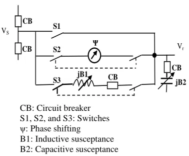
APST, on the other hand, is defined as a device, equipment, or dynamic electrical system capable of increasing or reducing the power flow of an electrical power transmission line in normal and post-contingency operations. The simplest configuration of the APST given in figure 2, shows that it consists of a phase shifting transformer connected in parallel with a reactance.
Figure 2. APST Single-line diagram [3]
VS
Ψ S2
CB S1 CB
jB2 CB
S3 jB1 CB
Vr
CB: Circuit breaker S1, S2, and S3: Switches ψ: Phase shifting B1: Inductive susceptance B2: Capacitive susceptance
The power transmitted by the line is now given by equation (3) which follows from equation (1).
The nature of this susceptances (B1, B2) depends on the operating quadrant of APST: capacitors to increase power flow and inductive reactors if APST is working to reduce it.
B. Interphase Power Controller 240 (IPC 240)
IPC 240, which consists solely of passive elements, is the main device of this family. As shown in its three-phase diagram given in figure 3, it is connected in series and consists of two parallel branches per phase, each having a susceptance (inductive or shunt capacitor) with a phase shifting element. This phase shifting element may be a conventional phase-shifting transformer, a conventional transformer provided with auxiliary winding to produce the desired internal phase shift, or a rotary transformer.
Figure 3. Three phase diagram of IPC 240
VS_C
Vr_C
VS_A
VS_B
Ψ2
Ψ1 jB1
jB2 VS_B
Vr_B
VS_C
VS_A
Ψ2
Ψ1 jB1
jB2
VS_A Vr_A
VS_B
VS_C
Ψ1 jB1
jB2
B1: Mutual susceptance1 (inductive or shunt capacitor)
B2: Mutual susceptance2 (inductive or shunt capacitor)
ψ1,2: Phase shifting
This IPC is characterized by its angle, 240°, which represents the angle difference between the sending end voltage applied to the susceptances. This angle can be determined according to table 1, this IPC is said to type 240 with two branches.
In the absence of contingency, this IPC provides robust and bidirectional control of power flow by absorbing or generating reactive power. The desired operating levels are obtained by adjusting the phase shifts, by tap changer adjusting or by variation of the susceptances [4].
One of the properties of this IPC, and its superiority over APST, is its ability to limit the fault current. Indeed, during this contingency, the susceptances are set such that |B1| = |B2|, and the device imposes an infinite impedance to the short circuit, thus relieving the circuit breakers.
TABLE I. ANGLE CHARACTERISTIC OF THE IPC240 SEEN PHASES A,B AND C OF A THREE-PHASE LINE
Sending end phase
side
Receiving end phase
side
Phase shift ψ Angle of the IPC (γ = ψ2 - ψ1)
C A - 120° = ψ1
240°
B 120 °= ψ2
A B - 120 ° = ψ1
C 120 °= ψ2
B C - 120 ° = ψ1
A 120 °= ψ2
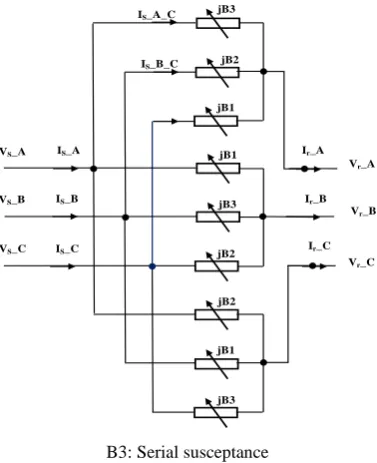
transmission lines), continuity of three-phase power supply to the load [6-8]. The diagram of a single IPC 240 with three branches is presented in Fig 4.
Figure 4. Topology of an IPC 240 with three branches
IS_B_C
IS_A_C
jB1 jB2 jB3
Vr_A
Ir_A
jB3 jB1 jB2
Vr_C
Ir_C
jB2 jB3 jB1 VS_A
VS_B
VS_C
Vr_B
Ir_B
IS_A
IS_B
IS_C
B3: Serial susceptance
For each reverse sequence compensator (B1, B2 and B3) at the input side, the following equation should be satisfied:
+
As an implication, it might be built using either two inductances and a capacitance, or one inductance and two capacitances. Hence, the relations to be used for computing the values of reactances are as follows:
• Currents Is_X_C in the reverse sequence compensator for X ε {A, B, C}:
• Resistance R2_CI and reactance X2_CI in the reverse sequence compensator:
• Serial and mutual (interphase) susceptances of the reverse sequence compensator.
The same reasoning from equation (4) to (7) could be used to obtain similar expressions of the susceptance B11, B22 and B33 at the output side (Dual IPC 240). In (6), Vs_A = Vs δsr°, δsr being a power angle. Consequently, each inverse sequence reactance defined in (6) given (3), evolves according to a real function of δsr. The graph of functions B1 (δsr), B2 (δsr), B3 (δsr), B11 (δsr), B22 (δsr) and B33 (δsr), obtained using a simple Matlab program from the following set of data {voltage Vs = Vr = 225 kV, line impedance Z = 10.49 + j 40.90, δsr
ε
[1° - 30°]}, are represented in Fig 5 [7].Figure 5. Graph of the inverse sequence susceptances
0 5 10 15 20 25 30
-1.5 -1 -0.5 0 0.5 1 1.5x 10
4
Power angle (degree)
Inve
rs
e
s
e
que
nc
e
r
e
a
c
ta
nc
e
(
ohm
)
B11 B22 B1 B3 B2
B33
In Fig 5, relation (4), is quite apparent. In addition, a new finding arising from Fig 5 is that, the variations of the reverse sequences susceptances of an IPC 240 with three branches fall into the family of simple exponential or polynomial functions of the power angle δsr.
C. Interphase Power Controller 120 (IPC 120)
IPC 120 is part of the synchronous topologies of this technology. Figure 6 shows its three-phase diagram, which essentially comprises a multi-tap transformer, three inductive reactors and three capacitors grouped two by two on each phase of the receiving side of the device.
The reactances B1 and B2 are connected to the Y-y6 transformer according to Table 2. As long as these forms of voltages are out of phase by 120 °, this IPC is said to be of type 120.
TABLE II. CONNECTION DIRECTION IN THE IPC120°
Secondary winding phase of the transformer
Receiving end phase of the
reactance
Total angle
Vbs and Vcs VAr
120° Vcs and Vas VBr
When this IPC is symmetrical, the current IAS is equal to the total of currents IB1 and IB2, phase shifted by -60 ° and +60 °, respectively. By adjusting the values of the reactances, this IPC provides full control of the magnitude and phase angle of the currents IAS, IBS, and ICS or simultaneously, the full control of IAR, IBr, and ICr. It is then possible to control the power SS and Sr [5].
It is important to note that during contingencies of such magnitude, this IPC can help maintain the voltage profile by generating or absorbing reactive power as it reduces power flow between sub-networks. When a short circuit occurs on either side of the IPC 120, these reactances limit the fault current. This IPC is sometimes preferred because of its installed reactive power, which is lower than IPC 240 [5].
By adjusting the value of the susceptances, the IPC thus provides full control of powers as defined in equation (8).
Figure 6. Three phase diagram of the IPC 120
Sec
ond
ary
wind
ing
P
rima
ry
wind
ing
IS_B IS_C IS_A
VS_A VS_B VS_C
jB1 jB2 jB1 jB2 jB2
jB1
I_B2 I_B1
Ir_A Ir_B Ir_C Vr_C Vr_B
Vr_A
Is_X: Source current of phase X, for X € {A, B, C} Ir_X: Receiving current of phase X
I_B1: Inductive reactor current; I_B2: Capacitor current
The angles δB1 and δB2 are the phase shifts appearing between the voltages on the secondary winding side and reception side of susceptance B1 and B2 respectively.
D. United Interphase Power Controller (UIPC)
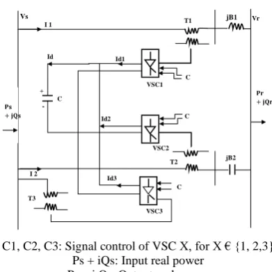
UIPC is based on an IPC 240 in which the phase-shifting is replaced by Static Synchronous Series Compensators (SSSC). Each phase of UIPC consists
in figure 7. The DC bus of all the three VSC modules is connected to the same bus. VSCs 1 and VSCs 2 are connected to the AC network by two series coupling transformers T1 and T2.
Considering the model shown in figure 7, the output apparent power of each UIPC branch is determined as follows:
)
The main function of transformer is the injection of the voltage which ideally shift the phase angle of Vs. The VSC 3 is connected to the shunt transformer T3 to the input bus of UIPC. VSC 3 provides the active power-exchange between the two VSCs by regulating the DC bus capacitor voltage and the magnitude of Vs.
Figure 7. UIPC Single-line diagram
jB1
Id3 I 2
T2
C
VSC3
jB2
T3
𝐏𝐫
+𝐣𝐐𝐫
T1 I 1
Vs Vr
𝐏𝐬
+𝐣𝐐𝐬
VSC1
VSC2
-+
Id2 C
C Id1
Id
C
C1, C2, C3: Signal control of VSC X, for X € {1, 2,3} Ps + iQs: Input real power
Pr + j Qr: Output real power
Thus, UIPC has the same power flow control properties as well the magnitude of the voltage at the local bus as the mitigation of the fault current. Finally, with the presence of the SSSC in this device, the power controlled by UIPC is greater than that of IPC 240 [9-11].
III. BENEFITSANDCOMPARISON
A. Advantages
IPC technology can be used in several power system applications for harmonic-free operations:
• Active and reactive power control under normal and post contingency conditions,
• Stabilize the flow of power between two sub-networks,
• When this device is tuned, it is used mainly for the fault current mitigation of the short circuit current so that the short circuit on one side of the IPC is not transferred to the other side of this IPC.
B. Comparison
Two basic observations can be made such as the behavior of this device compared to a transmission line, with or without series compensation, and a phase-shifting transformer.
TABLE III. COMPARISON OF IPC SENSITIVITY TO CERTAIN EQUIPMENT
Equipment Sensitivity to power angle δ
P Q
IPC Low High
Series or non-series compensated line
High Low
Phase-shifting transformer High Low
Another comparison of this technology with conventional solutions to solve power system problems is presented in Table 4 [13,14].
TABLE IV. COMPARISON OF IPC TECHNOLOGY WITH CONVENTIONAL SOLUTIONS
Classic solution Application Main advantage of
IPC over classic solution
High Voltage Direct Current
(HVDC) link
Asynchronous link
No generation of harmonic. No reactive power
consumption Robustness.
Phase-shifting transformer
Synchronous link
Passive real power control. Fault current
limitation.
System or transformer station redesign
Transformation or capacity increase
Cost reduction in certains cases. Maintenance of operating flexibility.
Phase-shifting transformer
Line power flow control
Cost reduction Lost reduction
ACKNOWLEDGMENT
The entire study has been conducted in the Laboratory of Computer Engineering and Automation, University of Douala. We would like to thanks all the members and students who help us directly or indirectly to successfully conduct the study.
CONCLUSION
With over twenty years of research and development, IPC technology can be considered mature. This paper presents the main features of the main Interphase Power Controller by describing the importance of each property. It also emphasizes the role of IPC devices in power transmission lines to ensure good control and specially to limit fault currents. Finally, a comparison of its functions vis-à-vis traditional solutions was recalled.
REFERENCES
[1] L. Angquist, B. Lundin and J. Samuelsson, « Power Oscillation Damping Using Controlled Reactive Power Compensation - A Comparison Between Series And Shunt Approaches», IEEE, N°92 SM 539-7 PWRS.
[2] J. Lemay, J. Brochu, F. Beauregard, P. Pelltier, « Interphase Power Controller-complementing the family of FACTS controllers », IEEE Canadian Review , page 1-5, Summer 2000.
[3] J. Lemay et al., « The Plattsburgh Interphase Power Controller », IEEE, Transmission and Distribution Conference, New Orleans, Vol 2, pp 648-653, Avril 1999. [4] J. Brochu, « Interphase Power Controller », second edition,
CITEQ, ABB, Polytechnic International Press, 2001, pages 31, 55-58.
[5] J.Brochu, G. Morin, F. Beauregard, P. Pelletier,« The Interphase Power Controller A New Concept For Managing Power Flow Within AC Networks », IEEE Transaction on Power Delivery, page 834,839, April 1994.
[6] J. J. Mandeng, C. H. Kom and J. Mbihi, « Modeling And Simulations of an Electric Power Transmission Line Under Asymmetric Compensation by Dual Interphase Power Controllers », International journal of energy conversion, pp 111-117, july 2015.
[7] J. J. Mandeng, J. Mbihi, and C. H. Kom « Design of an Automed Dual IPCs 240 system for Asymmetric Power Flow Compensation in an AC Electric Network », Transactions on electical engineering, pp 32-39, vol 6, 2017.
[8] J. J. Mandeng “Etude d’un nouveau système de compensation asymétrique de ligne de transport d’énergie électrique par régulateur de puissance interphase duaux à trois branches” thèse de Doctorat / PhD, Université de Douala – Cameroun, pp 141, 2018
[9] B. Gopinnath, S. Suresh Kumar, N. Vinothini, « Modeling of Unified Interphase Power Controller (UIPC) and Its Comparison with IPC and UPFC », International journal of Engineering Research and Technology, pp 65-69, Oct. 2013. [10] M. Firouzi, G. B. Gharehpetian, B. Mozafari, « Power-Flow
Control and Short-Circuit Current Limitation of Wind Farms Using Unified Interphase Power Controller », IEEE Transactions on Power Delivery, pp 62-71, feb 2017. [11] M. Najjar, S. Farhangi and H. Iman-Eini « A Method to
control the Interphase Power Controller with Comon DC bus » Electric Power Components and systems, pp 1-11, 2017.
[12] Y. Shan, Yu Ji-Lai, G. Zhi-zhong, « Performances Coordination Strategies of Dynamic Controlled Inter-phase Power Controller (DCIPC) », International Confernce on Power System technology-POWERCON, pp 367-372, nov 2004.
[13] M. Young, The Technical Writer's Handbook. Mill Valley, CA: University Science, 1989.