Journal of Electrical Engineering,
Electronics, Control and Computer Science
JEEECCS, Volume 3, Issue 7, pages 7-12, 2017
Traveling-Waves-Based Ground Fault Location
Using Zero-Sequence Detection and Wavelet
Transform
Saeed Roostaee
Research Scholar, Department of Electrical Engineering, Faculty of Engg. & Tech., Jamia
Millia Islamia, New Delhi, India [email protected]
Shabana Mehfuz, Mini Shaji Thomas, and Majid Jamil
Department of Electrical Engineering, Faculty of Engg. & Tech., Jamia Millia Islamia,
New Delhi, India
Abstract: Travelling Wave (TW) based fault location is considered as a very accurate model, however, it needs high sampling frequency to detect faults. Also it is a costly method when applied. To overcome the problem of precise fault detection, this paper proposes a zero fault detection and TW theory to determine the location of ground faults in a transmission line. The proposed algorithm is simulated and tested in the PSCAD software. A laboratory setup is developed not only to discuss the problem of existing relays in TW based fault location, but also to compare the proposed method with impedance based fault location algorithms.
Keywords: traveling wave based fault location, transmission line fault location.
I. INTRODUCTION
Statistics shows 70-80 percent of faults in transmission lines are single line to ground. They pose a serious threat to the safety of power system. Accurate fault location algorithm plays a vital role to estimate the location of these faults. TW based fault location algorithm have been increasingly investigated due to advancement in the technology, especially digital electronics, satellite based synchronization, and digital communications. In fault location based on traveling wave, each terminal of a line calculates the accurate time of the arrived surge due to a fault. As the surge speed is same as the light speed, comparing the arrived surge wave on each terminal of a line can estimate the location of faults. Using the standard time reference at the both sides is the first requirement in this technique. Therefore, communication system, accurate time stamping, appropriate current or voltage sensor and microprocessor protection relay are required.
The accuracy of TW based fault location technique is depending on the accuracy of fault detection system and the time stamping system. Several papers have been published and proposed different algorithms to improve the accuracy of TW based fault location. The authors of [1] propose to filter the power frequency from Current Transformers (CTs) by high-pass filter and sample the remained frequency to determine whether a fault happened in the line or not. This method needs a high sampling frequency of three phase signals. The authors of [2] developed a function for TW based fault location
using IEC61850, and they used transient fault report data in their function. However, in a practical case, the sampling frequency of the IEC61850-9-2 Sample Values (SV) is usually less than 20 kHz which is not sufficient for TW based fault location.
Wavelet transform is a powerful method to detect fault from the analysis of transient fault data [3-5]. It can be used to extract some features of a signal [6]. Thereafter, many scholars have applied these features in their algorithms, to improve the accuracy of TW based fault location. For instance, combination of wavelet and Artificial Neural Network (ANN) is applied to estimate the distance to fault is presented in [7]; The authors of [8] applied Hilbert Discrete Wavelet Transform; Reference [9] used neural network and wavelet transform; The authors of [10, 11] proposed TW based fault location for multi terminal circuits.
There has been many extensive researches on TW based fault location. However, very few of them have considered faulting detection strategy. While many algorithms have been developed in simulation software, the fault detection for TW based fault location in transmission lines still has technical problems. One of the main problems is that most of the algorithms need a high sampling frequency of three phase system which is costly in application. This paper proposes the detection of zero sequence components which is a digital value and easy to monitor with high frequency. In this basis, the time of detection of zero-sequence components is applied as the time of wave arrival. Technical detail of zero-sequence component detection based on the Current Transformers (CT) and Capacitor Voltage Transformers (CVT) data is considered in this paper. Thereafter, the algorithm of estimation to fault is introduced. And a laboratory setup has been developed to show the problems of existing relays in TW based fault detection.
II. TRAVELLING WAVE IN GROUND FAULT When a fault occurs on transmission lines, impulse signals or travelling wave are generated. The waves can be monitored in the both end of a transmission line. Ground fault is one of the most common reason of generation of TW. Where the wave of voltage and current can be described by Eq. (1) and (2).
( , )
f(
)
r(
)
e x t
e x vt
e x vt
q. 1
1
( , )
f(
)
r(
)
i x t
e
x vt
e x
vt
Z
Z
q. where e is Voltage wave, i is current wave, ef and
er are equation of forward wave and backward wave
respectively, Z is the impedance of line, v is wave velocity, t is time, and x is the distance from the measuring point.
Based on the velocity and travelled time, TW based fault location are applied travel time of the fault waves to estimate the location of the fault which can be obtained from Eq. (3).
T
2
F
v
x
Eq. WhereT is signal travel time, and xF is estimated fault location.
To improve the performance of this technique, many scholars have proposed a number of methods and techniques. The authors of [12] propos to use wavelet transform. Transient fault data are usually non stationary signals. In the other words, their frequency contents change with time. Wavelet transform is a powerful method to analysis such signals. Based on the wavelet theory, signals can be decomposed into a series of wavelets from equation (4).
,
1
( )
(
)
S
t
t
s
s
Eq. Where ψ(t) is mother wavelet, s and
are scaleand translation parameter, and the term
1/
s
is utilized to normalize wavelet energy of different scales.Wavelet transform can be obtained by implementing discrete wavelet transform which is given by;
/2
,
( )
2
(2
t k)
j j
j k
t
Eq.
Where j is scale parameter, k is translation parameter, j in a parameter which can change the amount of signal compression, and k displaces the wavelet in time domain.
III. RECEIVING TRAVELLING WAVES BY ZERO -SEQUENCE DETECTION
There are several ways to detect a ground fault. One of a desirable method to detect a ground fault is to detect the zero-sequence components. In normal condition, the sum of the three phase currents/voltages is zero resulting in the zero output for zero sequence detection. On the other hand, in a fault condition, the sum of the three phase currents/voltages are not equal to zero due to zero-sequence detection. Following subsections explain the receiving travelling waves by CVT and CT.
A. Receiving TW by CVTs
Capacitor Voltage Transformers is an instrument transformer which is used in substations for voltage measurement. It converts high voltage to low voltage for substation automation and protection functions.
Capacitor Voltage Divider (CVD) and
electromagnetic transformer are the main part of a CVT. CVD convert the voltage level and electromagnetic transformer changes the voltage level to the standard values. Fig 1 shows the model of a CVT. There are two output in this model. One output is used by Power Line Carrier (PLC) for communication purpose and the other one is used by automation and protection systems.
Fig 1. CVT model
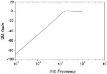
The frequency response of the output 1 and output 2 are shown in Fig 2dnaFig 3 stdaes .ysevstcepser
rn cfs nyssasntr ysevrnesh cfsTWs would pass through terminal 2. To detect zero sequence component based CVT, a current sensor is installed on the terminal 2 of a CVT, which can detect zero sequence component as follow:
0
E dV I C
dt
Eq.
Where C is the capacitance of CVT, and VE is the voltage of lines to ground.
9
Fig 3. Frequency response of output 2
B. Receiving TW by CT
Fig 4 shows the frequency response for different types of CTs. As the CTs have wider band-width than CVTs, it is perfectible to apply CTs in the proposed fault location algorithm. The zero sequence detection based on CT is as follow:
0 A B C
I
I
I
I
EqWhere IA, IB, and IC are the current of phase A, phase B, and phase C respectively.
Fig 4. Frequency response for different CT types
IV. PROPOSED METHOD
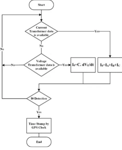
A flowchart for the proposed method is shown in Fig 5. The first stage in the process is that the calculation of I0 either from the output of CT or CVT. The next step is the I0 detection by wavelet transform algorithm. Once the I0 is detected, the time can be stamped by GPS clock. In this paper, we applied a component in PSCAD software to simulate wavelet transform algorithm. This component performs an on-line Discrete Wavelet Transform (DWT) on the input signal. Before the actual DWT is performed, the input signal is sampled at a rate, which is a user-specified input parameter. An option is also provided to enable or disable the internal anti-aliasing filter, and the type of mother wavelet along with its order may be selected from a list. This component supports several most commonly used types of mother wavelets:
Harr
Daubechies (order 1, 2, 4, and 8) Symlets (order 1, 2, 4, and 8)
Coeiflets (order 1 and 2)
The user can specify the level of detail computed. The amount of simulation time steps required to perform the wavelet transformation depends on the selected sampling frequency, mother wavelet type and the number of detail levels required. Therefore, output signals will exhibit a time delay with respect to the input signal; the amount of delay will depend on the selected parameters.
Fig 5. Proposed zero-sequence detection method
When a ground fault occurs on a transmission line, impulse signal or travelling wave of I0 is generated. Based on the proposed method, the wave can be detected in the both ends of the line. Detection time has to be stamped with high accuracy of time synchronization system (Fig 6)
Based on the TW fault location, the estimated fault distance from substation A can be calculated from (8).
1 2
( )
2
F
L L t t
Eq. Fig 6. Time synchronization in different substations
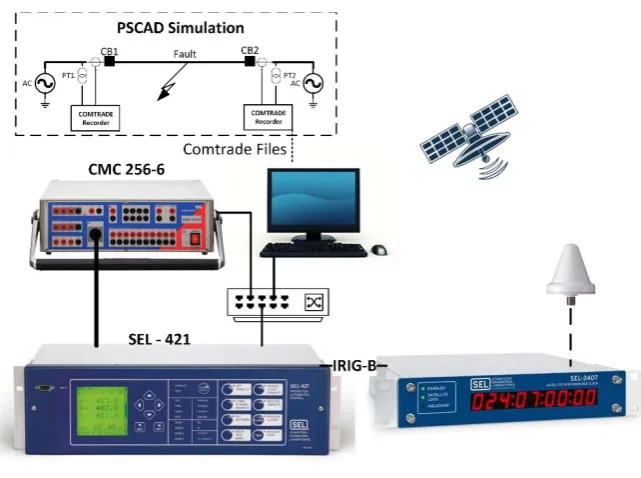
Fig 7. Lab setup
V. EVALUATION STUDY
In this section, results are analysed based on the simulation and experimental setup.
A. lab setup
Fig 7 illustrates the experimental setup for testing of fault location functions. In this setup, we can simulate faults in PSCAD software. The transient signals of simulated fault can be saved with the COMTRADE format [13]. Where a secondary test kit can play them and generate the real three phases voltage and current. The CMC256-6 is used as a secondary test kit in the setup. The three phase output signals of the CMC256-6 are connected to a transmission line protection relay. In the setup, we applied the SEL-421 relay which is a line protection relay. The relay is synchronized with the GPS clock. In this setup, the SEL-2407 is utilized as a satellite synchronized clock. Therefore, based on this setup, several faults can be simulated in transmission line and the associated signals can be generated to provide real values to evaluate the fault location functions
based on experimental results. Fig 8 shows an event viewer of a BG (phase B to ground) fault, which shows the time of I0 detection and fault detection. Similar observations can be archived for the other ground faults.
11
Fig 9. PSCAD Simulation
The accuracy of time is very important factor in TW fault location. It depends on the sampling frequency of measuring system as well as time synchronization. Fig 10 shows the time difference between two samples are 0.0005 seconds (2000 samples per second) in a relay IED where the higher sampling frequency is not economic. Thereafter, TW based fault location has to be a standalone device which is not convenient in application.
Fig 10. Accuracy of I0 detection
With the proposed scheme, I0 detection can be applied as a digital value instead of three phase analogue signals. Therefore, it can be monitored as an input or output signal with a higher sampling frequency resulting in a higher accuracy.
B. Numerical studies
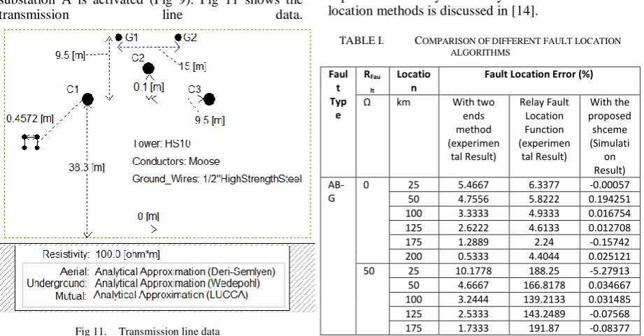
A 225 km transmission line is simulated in PSCAD software with 50 us sampling frequency to test the proposed scheme. An ABG (double phase to ground) fault at 0.22 second in 25 km far from substation A is activated (Fig 9). Fig 11 shows the
transmission line data.
Fig 11. Transmission line data
Based on the simulation results, I0 is detected at 0.220048783186 and 0.220399225664 second in substation A and substation B respectively (Fig 12).
Fig 12. I0 detection in substation 1 and 2 for the simulated fault
Based on the Eq. 7, the estimation of fault location can be obtained as 24.99871855 km far from substation A. To compare the accuracy of fault location based on different methods, the percentage error is determined as:
%
Estimation Actual*100
LineL
L
Error
L
Eq.
Where LEstimation is the estimated location by fault location algorithm, LActual is the actual location of the fault and LLine is the length of the line.
Several faults with different location, type and resistance are simulated with the proposed fault detection to analysis the proposed method. The summary of results is listed in TABLE I. The experimental study on relay and two end fault location methods is discussed in [14].
TABLE I. COMPARISON OF DIFFERENT FAULT LOCATION ALGORITHMS
Faul t Typ
e RFau
lt
Locatio n
Fault Location Error (%)
Ω km With two
ends method (experimen
tal Result)
Relay Fault Location Function (experimen
tal Result)
With the proposed shceme (Simulati on Result)
AB-G
0 25 5.4667 6.3377 -0.00057
50 4.7556 5.8222 0.194251
100 3.3333 4.9333 0.016754
125 2.6222 4.6133 0.012708
175 1.2889 2.24 -0.15742
200 0.5333 4.4044 0.025121
50 25 10.1778 188.25 -5.27913
50 4.6667 166.8178 0.034667
100 3.2444 139.2133 0.031485
125 2.5333 143.2489 -0.07568
200 1.0667 228.4 0.00057
BG 0 25 5.1556 5.6711 -0.00057
50 4.4444 5.9377 -0.11264
100 3.1111 6.6488 -0.02253
125 2.2667 7.1155 0.061811
175 0.8889 8.2133 0.08809
200 0.2222 8.7911 0.00057
50 25 5.1556 5.6933 0.048533
50 4.3556 6.6933 0.108321
100 2.8444 8.8933 -0.11582
125 2.1333 10.6889 -0.01675
175 1.6889 17.1289 0.08809
200 1.3778 23.3778 0.00057
ABG: Phase A to Phase B to ground BG: Phase B to ground
VI. CONCLUSION
TW based fault location has been a standalone device which is not convenient in application. The combination of TW based fault location with impedance based fault location can reduce the costs, improve convenience, and provide a superior fault location function in a protection relay.
To integrate TW based fault location with impedance based fault location, this paper proposed to apply I0 detection instead of fault location as the initial time of arrival of a ground fault wave, where it can be applied as an input to a relay. A laboratory setup had been developed to discussed the problems of existing protection relays in TW based fault location and to compare the accuracy of the proposed method with the impedance based fault location methods.
VII. REFERENCES
[1] E. O. Schweitzer, A. Guzman, M. V. Mynam, V. Skendzic, B. Kasztenny, and S. Marx, "Protective Relays with Traveling Wave Technology Revolutionize Fault Locating," IEEE Power and Energy Magazine,
vol. 14, pp. 114-120, 2016.
[2] Y. Chen, D. Liu, and B. Xu, "Wide-Area Traveling Wave Fault Location System Based on IEC61850,"
IEEE Transactions on Smart Grid, vol. 4, pp. 1207-1215, 2013.
[3] F. Costa, B. Souza, and N. Brito, "A wavelet-based algorithm to analyze oscillographic data with single and multiple disturbances," in Power and Energy Society General Meeting-Conversion and Delivery of Electrical Energy in the 21st Century, 2008 IEEE, 2008, pp. 1-8. [4] S. Santoso, E. J. Powers, and W. Grady, "Power quality
disturbance data compression using wavelet transform methods," IEEE Transactions on Power Delivery, vol. 12, pp. 1250-1257, 1997.
[5] Z. Xiaoli, Z. Xiangjun, L. Li, S. Choi, and W. Yuanyuan, "Fault location using wavelet energy spectrum analysis of traveling waves," in 2007 International Power Engineering Conference (IPEC 2007), 2007, pp. 1126-1130.
[6] P. E. Argyropoulos and H. Lev-Ari, "Wavelet Customization for Improved Fault-Location Quality in Power Networks," IEEE Transactions on Power Delivery, vol. 30, pp. 2215-2223, 2015.
[7] M. Choudhury and A. Ganguly, "An improved fault area detection & fault location methodology using wavelet transform," in 2015 International Conference on Energy, Power and Environment: Towards Sustainable Growth (ICEPE), 2015, pp. 1-6.
[8] Z. Moravej, M. Movahhedneya, G. Radman, and M. Pazoki, "Effective fault location technique in three-terminal transmission line using Hilbert and discrete wavelet transform," in 2015 IEEE International
Conference on Electro/Information Technology (EIT), 2015, pp. 170-176.
[9] M. Raoofat, A. Mahmoodian, and A. Abunasri, "Fault location in transmission lines using neural network and wavelet transform," in Electric Industry Automation (ICEIA), 2015 International Congress on, 2015, pp. 1-6. [10] R. J. Hamidi and H. Livani, "A travelling wave-based fault location method for hybrid three-terminal circuits," in 2015 IEEE Power & Energy Society General Meeting, 2015, pp. 1-5.
[11] Z. Moravej, M. Movahhedneya, G. Radman, and M. Pazoki, "Comparison of signal processing methods for traveling-waves fault location technique in three-terminal transmission lines," in 2015 IEEE International Conference on Electro/Information Technology (EIT), 2015, pp. 177-182.
[12] F. H. Magnago and A. Abur, "Fault location using wavelets," IEEE Transactions on Power Delivery, vol. 13, pp. 1475-1480, 1998.
[13] "IEEE Draft Standard for Common Format for Transient Data Exchange (COMTRADE) for Power Systems,"
IEEE PC37.111/D4, January 2012 (IEC 60255-24 Ed.2), pp. 1-72, 2012.
[14] S. Roostaee, M. S. Thomas, and S. Mehfuz, "Laboratory Investigation of Fault Location in Transmission Lines,"