Regression Test Selection Techniques: A Survey
Swarnendu Biswas and Rajib Mall
Dept. of Computer Science and Engineering IIT Kharagpur, India - 721302
E-mail: {swarnendu, rajib}@cse.iitkgp.ernet.in
Manoranjan Satpathy and Srihari Sukumaran GM India Science Lab, Bangalore, India
E-mail: {manoranjan.satpathy, srihari.sukumaran}@gm.com
Overview paper
Keywords:software maintenance, regression testing, regression test selection, model-based testing, UML, software com-ponents, embedded programs
Received:April 12, 2010
Regression testing is an important and expensive activity that is undertaken every time a program is mod-ified to ensure that the modifications do not introduce new bugs into previously validated code. An im-portant research problem, in this context, is the selection of a relevant subset of test cases from the initial test suite that would minimize both the regression testing time and effort without sacrificing the thorough-ness of regression testing. Researchers have proposed a number of regression test selection techniques for different programming paradigms such as procedural, object-oriented, component-based, database, aspect, and web applications. In this paper, we review the important regression test selection techniques proposed for various categories of programs and identify the emerging trends.
Povzetek: Podan je pregled tehnik izbora testov za regresijsko testiranje programov.
1
Introduction
Software maintenance activities, on an average, account for as much as two-thirds of the overall software life cycle costs [75]. Maintenance of a software product is frequently necessitated to fix defects, to add, enhance or adapt exist-ing functionalities, or to port it to different environments. Whenever an application program is modified for carrying out any maintenance activity, resolutiontest cases are de-signed and executed to check that the modified parts of the code work properly. Regressiontesting (also referred to as
program revalidation) is carried out to ensure that no new
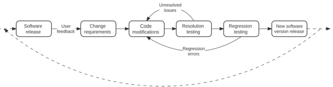
errors (called regression errors) have been introduced into previously validated code (i.e., the unmodified parts of the program) [55]. Although regression testing is usually asso-ciated with system testing after a code change, regression testing can be carried out at either unit, integration or sys-tem testing levels. The sequence of activities that take place during the maintenance phase after the release of a software is shown in Figure 1. The figure shows that after a software is released, the failure reports and the change requests for the software are compiled, and the software is modified to make necessary changes. Resolution tests are carried out to verify the directly modified parts of the code, while regres-sion test cases are carried out to test the unchanged parts of the code that may be affected by the code change. After
the testing is complete, the new version of the software is released, which then undergoes a similar cycle.
Regression testing is acknowledged to be an expensive activity. It consumes large amounts of time as well as effort, and often accounts for almost half of the software maintenance costs [55, 49]. The extents to which time and effort are being spent on regression testing are exemplified by a study [22] that reports that it took 1000 machine-hours to execute approximately 30,000 functional test cases for a software product. It is also important to note that hundreds of man-hours are spent by test engineers to oversee the re-gression testing process; that is to set up test runs, moni-tor test execution, analyze results, and maintain testing re-sources, etc [22]. Minimization of regression test effort is, therefore, an issue of considerable practical importance, and has the potential to substantially reduce software main-tenance costs.
Regression test selection (RTS) techniques select a sub-set of valid test cases from an initial test suite (T) to test that the affected but unmodified parts of a program con-tinue to work correctly. Use of an effectiveregression test
selectiontechnique can help to reduce the testing costs in
environments in which a program undergoes frequent mod-ifications. Regression test selection essentially consists of two major activities:
Software release
Change requirements User
feedback
Resolution testing
Regression testing
New software version release
Code
modifications Unresolved
issues
Regression errors
Figure 1: Activities that take place during software maintenance and regression testing.
identification of the unmodified parts of the program that are affected by the modifications.
– Test case selection - This involves identification of a subset of test cases from the initial test suiteT which
can effectively test the unmodified parts of the
pro-gram. The aim is to be able to select the subset of test cases from the initial test suite that has the potential to detect errors induced on account of the changes.
Rothermel and Harrold [78] have formally defined the regression test selection problem as follows: LetP be an
application program andP′ be a modified version of P.
LetT be the test suite developed initially for testingP. An
RTS technique aims to select a subset of test casesT′⊆T
to be executed onP′, such that every error detected when
P′is executed withT is also detected whenP′is executed
withT′.
Leung and White [57] have observed that the use of an RTS technique can reduce the cost of regression testing compared to the retest-all approach, which involves run-ning the entire test suite T to revalidate a modified pro-gramP′, only if the cost of selecting a reduced subset of test cases to be run onP′is less than the cost of running the tests that the RTS technique omits. Theretest-allapproach is considered impractical on account of cost, resource and delivery schedule constraints that projects are frequently subjected to. Another approach is to randomlyselect test cases fromTto carry out regression testing. However, ran-dom selection of test cases may fail to expose many regres-sion errors. RTS techniques aim to overcome the draw-backs associated with the retest-all approach and in random selection of test cases by precisely selecting only those test cases that test the unmodified but affected parts of the pro-gram.
Though substantial research results on RTS have been reported in the literature, several studies [35, 36] show that very few software industries deploy systematic test selec-tion strategies or automaselec-tion support during regression test-ing. The approaches that are most often used in the indus-try for identification of relevant regression test cases are either based on expert judgment, or based on some form of manual program analysis. However, selection of test cases based on expert judgment tends to become ineffective and unreliable for large software products. Even for moderately
complex systems, it is usually extremely difficult to man-ually identify test cases that are relevant to a change. This approach often leads to a large number of test cases being selected and rerun even for small changes to the original program, leading to unnecessarily high regression testing costs. What is probably more disconcerting is the fact that many test cases which could have potentially detected re-gression errors could be overlooked during manual selec-tion. Another problem that surfaces during regression test-ing stems from the fact that testers (either from the same or-ganization or from third-party companies) are usually sup-plied with only the functional description of the software, and therefore lack adequate knowledge about the code to precisely select only those test cases that are relevant to a modification [74].
A large number of RTS techniques have been reported for procedural [5, 7, 10, 37, 43, 44, 54, 56, 58, 80] and object-oriented programs [4, 14, 41, 73, 82], each aimed at leveraging certain optimization options. These techniques trade-off differently with regards to the cost of selection and execution of test cases and fault-detection effective-ness. In the recent past, the problem of RTS has actively been investigated and new approaches have emerged to keep pace with the newer programming paradigms. Dur-ing the last decade, there has been a proliferation in the use of different programming paradigms such as component-based development, aspect-oriented programming, embed-ded and web applications, etc. It is, therefore, not surpris-ing that a number of RTS techniques have been proposed for component-based [31, 66, 67, 72, 115, 116, 117], aspect programs [114, 109], web applications [86, 93, 61, 110, 85], etc.
the nature of the empirical data considered. The studies reported in [25, 24] are based on the similarities of the dif-ferent RTS techniques and the quality of the empirical data used. Engström et al. [25] observe that it is very diffi-cult to come up with an RTS technique which is generic enough (i.e., can be applied to different classes of applica-tions) and is superior to all other techniques. The survey carried out by Engström et al. considers techniques which have been published before 2006. Therefore, their survey does not include many RTS techniques proposed after 2006 [114, 109, 18, 61, 86, 93, 85, 65, 31], and also does not in-clude a few RTS techniques which were proposed before 2006 [10, 110, 107]. Moreover, their study does not in-clude a detailed discussion about the merits and demerits of each technique.
In this paper, we present a detailed review of the RTS techniques proposed for different programming paradigms such as procedural, object-oriented, component-based, database, aspect and web software. Since a large number of RTS techniques have been proposed in the literature, we have limited our study to only the more prominent classes of RTS techniques. The techniques we have reviewed have been chosen based on their prominence determined by the number of citations and their frequency of referrals in other related studies. Our sources of information are existing re-views on RTS techniques [79, 6, 8, 25, 24, 34, 112], the citation index of the papers that we studied, and the on-line digital libraries, such as IEEE Xplore, ACM Digital Library, ScienceDirect, etc. The keywords that we used for our search on the online digital libraries includeregression
testing,regression test selection,test selection, etc. As an
aid to understanding, and to keep the size of the review manageable, we have classified different RTS techniques together into relevant classes based on the motivation and similarity of the proposed approaches. We present a brief discussion on the working of each class of techniques, and discuss the merits and demerits of each. We also discuss issues that arise while designing RTS techniques for em-bedded programs, and identify the emerging trends in re-gression testing.
This paper is organized as follows: Section 2 presents basic concepts related to regression testing and which have been used in the rest of this paper. In Section 3, we discuss and compare various RTS approaches proposed for proce-dural programs. Subsequently, we discuss RTS techniques for object-oriented, component-based, database, web and AspectJ programs in Sections 4, 5, 6, 7, and 8 respectively. We discuss techniques for RTS of embedded software in Section 9. We discuss RTS techniques proposed for .Net and BPEL programs in Section 10. We discuss future re-search directions in regression testing and finally conclude the paper in Section 11.
2
Basic Concepts
In this section, we first discuss a few basic concepts that are extensively used in the context of regression testing. We then discuss some popular intermediate representations which are used for program model-based RTS.
For notational convenience, in the rest of the paper we denote the original and the modified programs byP and P′respectively. The initial regression test suite is denoted byT, and a test case inT is denoted byt.
2.1
Concepts Related to Regression Testing
In this section, we discuss a few important notations and concepts relevant to regression testing.
Obsolete, Retestable and Redundant Test Cases:
Ac-cording to Leung and White [55], test cases in the initial test suite can be classified as obsolete, retestable and re-dundant (or reusable) test cases. Obsolete test cases are no more valid for the modified program. Retestable test cases are those test cases that execute the modified and the affected parts of the program and need to be rerun during regression testing. Redundant test cases execute only the unaffected parts of the program. Hence, although these are valid test cases (i.e., not obsolete), they can be omitted from the regression test suite without compromising the quality of testing.
Execution Trace of a Test Case The execution trace of a test case t on a programP (denoted byET(P(t))) is defined as the sequence of statements in P that are exe-cuted whenP is executed witht[80]. The execution trace information forPcan be generated by appropriately instru-menting the source code.
Fault-revealing Test Cases: A test case t ∈ T is said to befault-revealingfor a programP, iff it can potentially causeP to fail by producing incorrect outputs forP [79].
Modification-revealing Test Cases: A test caset∈Tis considered to bemodification-revealingforP andP′, iff it produces different outputs forPandP′[79].
Modification-traversing Test Cases: A test caset ∈T
is modification-traversing for P and P′, iff the
execu-tion traces of t onP andP′ are different [79]. In other words, a test case t is said to be modification-traversing if it executes the modified regions of code in P′. For a given original program and its modified version, the set of modification-traversing test cases is a super-set of the set of the modification-revealing test cases.
selects modification-revealing tests from the initial regres-sion test suiteT [79]. Let us consider an initial test suiteT containingnmodification-revealing test cases. If an RTS techniqueM selectsmof these test case, the inclusiveness of the RTS techniqueM with respect toP, P′ andT is expressed as(m/n)∗100[79].
AsafeRTS technique selects all those test cases from the initial test suite that are modification-revealing [79]. There-fore, an RTS technique is said to be safe, iff it is 100% in-clusive. Regression test cases that are relevant to a change but are not selected by an RTS technique are instances of
false negatives. Therefore, an RTS technique is safe if the
test suite selected by it has no false negatives [18].
Precision measures the extent to which an RTS algorithm ignores test cases that are non-modification-revealing [79]. Test cases that are selected by a technique but are not rel-evant are false positives. An RTS technique is, therefore, precise iff it there are no false positives among the selected test cases [18].
2.2
Regression Test Suite Minimization and
Prioritization
Regression test suite minimization (TSM) techniques [40, 62, 64] aim to reduce the size of the regression test suite by eliminating redundant test cases such that the cover-age achieved by the minimized test suite is same as the initial test suite. Different studies published in the litera-ture [83, 106, 62] report conflicting results on the impact of TSM techniques on the fault-detection capabilities of the reduced test suites. Lin et al. have observed [62] that the TSM problem isNP-complete, since the minimum set-covering problem [20] can be reduced to the TSM problem in polynomial time.
Regression test case prioritization (TCP) techniques [23, 99, 84] order test cases such that test cases that have a higher fault-detection capability are assigned a higher pri-ority and can gainfully be taken up for execution earlier. TCP approaches usually aim to improve the rate of fault de-tection by the ordered test suite [23, 84]. The main advan-tage of ordering test cases is that bugs are detected and can be reported to the development team early so that they can get started with fixing the bugs [84]. Also TCP techniques provide testers with the choice of executing only a certain number of higher priority test cases to meet the given time or cost considerations. This is advantageous especially in case of unpredicted interruptions to testing activities on ac-count of delivery, resource or budget constraints.
Several TSM and TCP approaches have been proposed in recent years, and have emerged as active areas of re-search by themselves. However, our current work focuses only on RTS techniques. More detailed information about TSM and TCP approaches can be found in [22, 23, 112].
Service Provider
Service Broker (UDDI)
Service Requester
Publ ish
(WS DL
)
Bind (SOAP)
Find (WSDL)
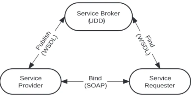
Figure 2: Web service architecture.
2.3
Few Other Relevant Concepts
In the following, we briefly discuss few other concepts that are relevant to this survey.
Program Slicing: Program slicing is a program analysis technique which was first introduced by Weiser [103] to aid in program debugging. A program slice is usually defined with respect to a slicing criterion. A slicing criterionSC is a pair< p, V >, wherepis a program point of interest andV is a subset of the program’s variables. A slice of a programP with respect to a slicing criterionSCis the set of all the statements of the programPthat might affect the slicing criterion for every possible input to the program.
Since the publication of Weiser’s seminal work, the con-cept of slicing has been extended and many slicing algo-rithms have been proposed in the literature for other ar-eas of program analysis such as program understanding, compiler optimization, reverse engineering, etc. More de-tailed information regarding program slicing can be found in [108, 95].
Web Services: Web services are now being extensively used in application development across distributed and re-mote platforms, and are examples of service-oriented ar-chitecture (SOA) based development. SOA-based develop-ment has received a big boost with the advent of standard-ized web services. Aweb servicecan be defined as a soft-ware component which implements a logic and is designed to be inter-operable over a network providing platform-independence.
Figure 2 shows the typical architecture and the specifi-cations of a web service [93, 13]. A service provider pub-lishes services to a service broker. Service requesters find required services using a service broker and then bind to them. Platform independence is achieved through use of the following web specifications:
int a, b, sum;
1. read( a );
8. sum = b; 3. sum = 0; 4. while ( a < 8 ) { 5. sum = sum + b; 6. a = a + 1; } 7. write( sum );
9. write( sum ); 2. read( b );
Figure 3: A sample program.
they can be exchanged between applications regard-less of the development platform and the program-ming language being used.
– Web Service Description Language (WSDL) - WSDL is an XML-based language that is designed to provide an interface between a web service and its users.
– Universal Description Discovery and Integration (UDDI) - UDDI is an XML-based information reg-istry where servers can publish their services. It al-lows users to locate any specific web services they might be interested in.
2.4
Graph Models for Procedural Programs
Graph models of programs have extensively been used in many applications such as program slicing [60, 89], impact analysis [52], reverse engineering [19], computa-tion of program metrics [100], regression test seleccomputa-tion [80, 73, 41, 7], etc. Analysis of graph models of programs is more efficient compared to textual analysis, and various types of relationships among program elements are also not explicit in the code. This has led to several representations such as Control Flow Graph (CFG) [3], Program Depen-dence Graph (PDG) [29] and System Dependence Graphs (SDG) [46] being proposed for procedural programs. In the following, we briefly discuss the important graph models proposed for procedural programs.
2.4.1 Flow Graph
A flow graph for a programP is a directed graph(N, E) where the program statements correspond to the set of nodesN in the flow graph, and the set of edges E repre-sent the relationships among the program statements. How-ever, the nodes in a flow graph can also correspond to basic blocks in a program. Typically it is assumed that there are two distinguished nodes called start with in-degree zero andstop with out-degree zero. There exists a path from startto every other node in a flow graph, and similarly, there exists a path from every other node in the graph to stop.
2.4.2 Control Flow Graph
A control flow graph (CFG) [3] is a flow graph that rep-resents the sequence in which the different statements in a program get executed. That is, it represents the flow of ex-ecution of control in the program. In fact, aCFGcaptures all the possible flows of execution of a program.
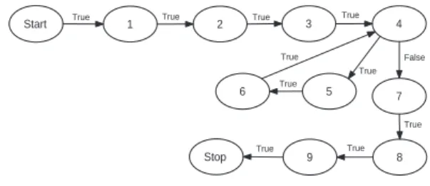
The CFG of the program P is the flow graph G = (N, E)where an edge(m, n)∈Eindicates possible flow of control from nodemto noden. Figure 4 represents the CFGof the program shown in Figure 3. Note that the exis-tence of an edge(x, y)in aCFGdoes not necessarily mean that controlmusttransfer fromxtoyduring a program run.
Start 1 2 3 4
5
True
False
True True True
6 7
True True
True
8 9
Stop
True
True True
Figure 4: CFGfor the example program shown in Figure 3.
2.4.3 Data Dependence Graph
Dependence graphs are used to represent potential depen-dencies between the elements of a program. In the fol-lowing, we discuss data and control dependencies between program elements and their graph representations.
Data Dependence: LetGbe theCFGof a programP. A noden∈Gis said to be data dependent on a nodem∈G, if there exists a variablevarof the programPsuch that the following hold:
1. The nodemdefinesvar, 2. The nodenusesvar,
3. There exists a directed path frommtonalong which there is no intervening definition ofvar.
Consider the sample program shown in Figure 3 and its CFGshown in Figure 4. From the use of the variablessum andbin line 5, it is evident that node 5 is data dependent on nodes 2, 3 and 5. Similarly, node 8 is data dependent on only node 2. However, node 8 is not data dependent on either of the nodes 3 and 5.
Data Dependence Graph: The data dependence graph
2.4.4 Control Dependence Graph
The concept of control dependence [3] captures the depen-dency existing between two program elements when the execution of the second element is dependent on the out-come of the first.
Dominance: If xandy are two nodes in a flow graph, thenxdominatesy iff every path fromstarttoy passes through x. Similarly, y post-dominates x iff every path fromxtostoppasses throughy.
Let x and y be two nodes in a flow graph G. Node x is said to be the immediate post-dominator of node y iff x is a post-dominator ofy, x ̸= y and every other post-dominator z ̸= xofy post-dominatesx. The post-dominator tree of a flow graphGis the tree that consists of the nodes ofG, hasstopas the root node, and has an edge (x, y)iffxis the immediate post-dominator ofy.
Control Dependence: LetGbe theCFGof a program
P. Letxandy be two arbitrary nodes in G. A nodey is said to be control dependent on another node xif the following hold:
1. There exists a directed pathQfromxtoy,
2. ypost-dominates everyzinQ(excludingxandy), 3. ydoes not post-dominatex.
The concept of control dependence implies that if y is control dependent onx, thenxmust have multiple succes-sors inG. Conversely, ifxhas multiple successors, then at least one of its successors must be control dependent on it. Consider the program of Figure 3 and itsCFGin Figure 4. Each of the nodes 5 and 6 is control dependent on node 4. Note that although node 4 has two successor nodes 5 and 7, only node 5 is control dependent on node 4.
Control Dependence Graph: The control dependence
graph (CDG) of a program P is the graph GCDG = (N, E), where each noden ∈ N represents a statement of the programP, and(x, y)∈E, iffyis control depen-dent onx.
1
6
4
8
9 2
5 3
7
data dependence edge control dependence edge
Figure 5:PDGof the program in Figure 3.
2.4.5 Program Dependence Graph
The program dependence graph (PDG) [29] for a program P explicitly represents both control and data dependencies in a single intermediate representation ofP. ThePDGof a programP is a directed graphGP DG= (N, E), where each noden∈Nrepresents a statement of the programP. A PDG contains both control dependence and data depen-dence edges. A control (or data) dependepen-dence edge(m, n) indicates thatnis control (or data) dependent onm. There-fore, the PDG of a program P is the union of a pair of graphs: the data dependence graph of P and the control dependence graph ofP. ThePDGfor the program in Fig-ure 3 is shown in FigFig-ure 5.
2.4.6 System Dependence Graph
A major limitation of aPDGis that it can model only a single procedure and cannot handle inter-procedural calls. Horwitz et al. [46] enhanced the PDGrepresentation to handle procedure calls and introduced the system depen-dence graph (SDG) representation which models the main program together with all the non-nested procedures.
} int x = 0;
CE1 class A {
S4 B *bptr = new B();
S6 try { E2 void mA() { S3 int a = 0;
CE13 class B {
S16 if ( y < 0 ) S17 throw new E2();
S19 catch(E2 &e2) {
S11 cout<<"Error"<<endl; } S10 catch(...) {
S5 cin>>a;
C7 bptr−>mB(a); }
S9 cout<<"Error E1"<<endl; } S8 catch(E1 &e1) {
S15 try {
S18 x = sqrt(y); }
S20 cout<<"Error E2"<<endl;
E14 float mB( int y ) { S12 cout<<x<<endl; }
};
}; S21 throw; } S22 cout<<x<<endl; }
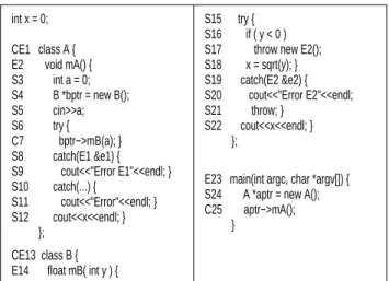
E23 main(int argc, char *argv[]) { S24 A *aptr = new A(); C25 aptr−>mA();
Figure 6: An example program.
AnSDGis very similar to aPDG. In fact, thePDGof the main program is a subgraph of theSDG. In other words, for a program without procedure calls, thePDGand theSDG are identical. The technique for constructing anSDG con-sists of first constructing a PDGfor every procedure, in-cluding the main procedure, and then adding auxiliary de-pendence edges which link together the various subgraphs while maintaining call-return discipline.
2.5
Graph Models for Object-Oriented
Programs
inadequate for representing object-oriented programs [60]. Therefore, various models for object-oriented programs such as the Class Call Graph (CCG) [42], Inter-procedural Program Dependence Graph (IPDG) [77], Class Depen-dence Graph (ClDG) [77, 78], and Java Interclass Graph (JIG) [41] have been proposed. In the following, we briefly discuss theClDGandJIGmodels.
CE1
S3 S4 S5 S6 S8 S12
C7
S9 S10
S11 y_in = a x_in = x
x = x_out
control dependence edge data dependence edge
E14
y = y_in x = x_in x_out =x
S15 S16 S18 S19 S22
S17 S20 S21
class member edge
E2 call edge
Figure 7:ClDGfor class A of the program shown in Figure 6.
2.5.1 Class Dependence Graph
A ClDG[77, 78] is an extensively used model for inter-mediate representation of object-oriented programs. Each method in a ClDG is represented by its corresponding PDG. A class in aClDGis denoted by aclass entrynode and the entry point for each method is represented by a
method entrynode. Theclass entrynode is connected to
eachmethod entrynode by aclass memberedge. A
repre-sentative driver node (RDN) is added to theClDGwhich summarizes the set of test driver routines used for class testing [77]. This RDN acts as the root of the ClDGfor the whole program. Each entry node of a public method of the class is directly connected to the RDN by means of
driver edges, thus implying that the driver routines can
in-voke the public methods of the class under test. For ex-ample, Figure 7 shows theClDGconstructed for classA of the program shown in Figure 6. The node labels in the ClDGcorrespond to the statement numbers in the program of Figure 6. The rectangular node labeledCE1in Figure 7 represents theclass entryvertex for classA. NodeE2 rep-resents amethod entrynode corresponding to the method
void A::mA(). The edgeCE1 →E2in Figure 7 is a
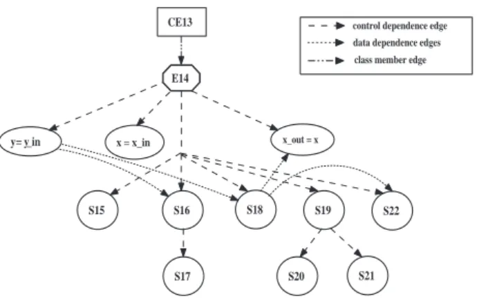
class memberedge. Figure 8 shows theClDGfor classB
defined in Figure 6.
CE13
y = y_in x = x_in x_out = x
S15 S16 S18 S19 S22
S17 S20 S21
control dependence edge data dependence edges class member edge
E14
Figure 8: ClDG for class B of the program in Figure 6.
2.5.2 Java Interclass Graph
Intermediate representations such asIPDGandClDGhave been proposed in the context of C++ programs and do not satisfactorily model Java programs. Harrold et al. pro-posed an extended control flow model for Java programs called Java Interclass Graph (JIG) [41] that extends aCFG to capture the following features of a Java program:
– Variable and object type information - The variable or object type information is stored in a JIG node. The names of classes are represented using the full inheritance hierarchy which helps to easily detect any change to the inheritance tree for the class in the mod-ified program.
– Internal and external methods of a class - Internal methods are represented in a JIG with an extended CFG. The extensions are: each call site is broken into acall and areturnnode. Thecall andreturnnodes are inter-connected with a pathedge that represents the execution path through the called method. Since the source code is usually not available for externally-defined methods, these are represented in aJIGusing collapsedCFGs.
– Calls to internal or external methods from internal methods - In a JIG, the call node is connected to the entry node of the called method with acalledge. There can only be one call edge if the method call is not polymorphic. For a polymorphic method call, the callnode is connected to the entry node of each method that can be bound to the call. The class hier-archy analysis technique [21] can be used to identify all possible virtual call bindings.
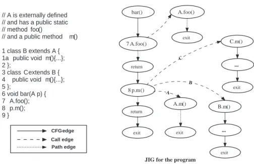
We illustrate the representation of method calls from internal methods in a JIGwith the help of an exam-ple reported in [41]. Figure 9 shows a code snippet with calls to methods foo()andm(). In the pro-gram, class B extends class A (external to the pro-gram) and overrides the methodm(). ClassCextends class B and also overrides method m(). For poly-morphic calls in aJIG, there exists an edge to all the methods for possible bindings. In the program, call to
bar()
return
8 p.m()
return
7 A.foo()
exit
A.foo()
exit
A.m()
exit
B.m()
...
exit
B C
C.m()
...
exit
A
CFG edge
Call edge Path edge
JIG for the program // A is externally defined
// and has a public static // method foo()
// and a public method m()
1 class B extends A { 1a public void m(){...}; 2 };
3 class C extends B { 4 public void m(){...}; 5 };
6 void bar(A p) { 7 A.foo(); 8 p.m(); 9 }
Figure 9: An example of method calls from internal methods in aJIG.
static binding. Therefore, in Figure 9, there exists only a singlecalledge between the nodes7 A.foo()and
A.foo(). The method callp.m()is polymorphic,
and there can be three possible bindings, one each for classA,B, andC. This is represented in theJIGby the three out edges from the node8 p.m(). Each outgoing edge connects to a possible method call to which it can bind during run-time.
– Calls to internal methods from external methods -There can be calls from externally-defined methods to internally-defined methods in Java due to inheritance and polymorphism. The external code is represented in aJIG as a node labeled ECN whereECN stands
forexternal code node. For each internal class that is
accessed from an external class, there is an outgoing edge from the ECN node to the class entrynode of that internal class.
– Exception handling - AJIG represents atry state-ment with atrynode. The code within thetryblock is represented as aCFG, and is connected with a con-trol flow edge with thetrynode. Eachcatch state-ment is represented using acatchnode, and the corre-spondingcatchblock is modeled using aCFG. The
catch node is connected with theCFG using a
con-trol flow edge. Thetrynode is connected to thecatch node of the first catchblock using a path edge la-beledexception. Afinallynode and aCFGare used to represent thefinallyblock of thetrystatement. Uncaught exceptions are modeled asexceptional exit nodes.
3
RTS Techniques for Procedural
Programs
RTS techniques were first studied in the context of proce-dural programs [55, 56]. RTS for proceproce-dural programs is, therefore, an extensively researched topic, and many tech-niques have been proposed over the years [17, 56, 58, 37, 43, 92, 54, 76, 5, 80, 97, 98, 7, 10]. These techniques se-lect relevant regression test cases using either control flow, data or control dependence analysis, or by textual analy-sis of the original and the modified programs. Depending on the type of the program analysis technique used and to aid in understanding, we have grouped the different RTS techniques into the following major classes:
1. Dataflow analysis-based techniques [43, 92, 44, 37] 2. Slicing-based techniques [7, 10, 2]
3. Firewall-based techniques [56, 58]
4. Differencing-based approaches [97, 98, 17] 5. Control flow analysis-based techniques [54, 80, 5]
In the following, we briefly discuss these different cate-gories of RTS techniques and compare their effectiveness. We base our comparisons on the set of metrics introduced by Rothermel and Harrold [79]: safety, precision, effi-ciency, and generality. Rothermel and Harrold have pre-sented a comprehensive survey of procedural RTS tech-niques in [79]. For the sake of completeness and continuity of the paper, we have included brief discussions on these techniques. We also discuss a few techniques [97, 98, 5] which were published after their work.
3.1
Dataflow Analysis-Based Techniques
Dataflow analysis-based RTS techniques explicitly de-tect definition-use pairs for variables that are affected by program modifications, and select test cases that exercise the paths from the definition of modified variables to their uses. The use of a variable is further distinguished into computation uses (c-uses) and predicate uses (p-uses). A c-use occurs for a variable if it is used in computations, and a p-use occurs when it is used in a conditional statement. A c-use may have an indirect effect on the control flow of the program, while a p-use may either directly affect the flow of control or may also indirectly affect some other program statements.
Harrold and Soffa [43] have proposed a dataflow coverage-based RTS technique that can be applied to ana-lyze changes across multiple procedures. Their approach involves processing the dataflow information incremen-tally, i.e., process a single change, select test cases for that change, and update the dataflow information and test cov-erage information. The same process is repeated for all the changes one by one. In their approach,Pis represented by aCFG, in which the nodes represent basic blocks. This re-duces the size of the flow graph and makes graph analysis more efficient as compared to representing the individual program statements as nodes. Additional nodes are intro-duced in the flow graph to model global variables, function parameters, and return values of functions. Modifications toP usually result in changes to the basic blocks or the control flow structure of the program. The information in each node of the flow graph is extended to include the as-sociated dataflow information for variables present in the node. For each variable definition in a node n, the node numbers of all the c-uses of the variable in the flow graph are stored in noden. The block numbers for all the p-uses of the variable are also stored inn. The information about the paths traversed whenP is executed on eacht ∈ T is used to select test cases which exercise the modified def-use pairs for any variable, and are selected for retestingP′.
Dataflow-based RTS techniques reported in [43, 92, 44] usually carry out analysis either by processing the changes one by one and then incrementally updating the dataflow information forP′, or compute the full dataflow informa-tion for P andP′ and compare the differences between def-use pairs. Both these approaches require saving the dataflow information across testing sessions, or recompute them at the beginning of each testing session. The program slicing-based RTS technique proposed by Gupta et al. [37] is based on inter-procedural slicing which does not require saving or recomputing the dataflow information across test-ing sessions. The technique uses the concepts of backward and forward slices to determine the affected def-use pairs that must be retested. The program to be regression tested is sliced to select test cases that execute the affected def-use pairs.
3.1.1 Critical Evaluation
The techniques reported in [37, 43, 44] are based on com-puting dataflows in a program and are not able to deter-mine the effect of program modifications that do not cause changes to the dataflow information [112]. The techniques also do not consider control dependencies among program elements for selecting regression test cases. As a result, these techniques are unsafe. Dataflow techniques are also imprecise because the presence of an affected definition or use in a new block of code does not guarantee that all test cases which execute the block will execute the affected code [79]. Examples illustrating the unsafe and imprecise nature of dataflow-based techniques are available in [79].
3.1.2 Slicing-Based Techniques
Agrawal et al. [2] have proposed a set of program slicing-based RTS techniques. The aim of these techniques is to select those test cases which can produce different outputs when executed with the modified program versionP′. The authors define a slice with respect to a test casetas the set of program statements which are executed whenP is exe-cuted witht. The authors have proposed four slicing tech-niques [2]: executionslice, dynamicslice, relevant slice,
andapproximate relevantslice. The RTS techniques
pro-posed in [2] select a test casetfor regression testing only if the slice of t computed using any one of the four ap-proaches contains a statement modified inP′.
A PDG-based slicing approach for procedural programs was proposed by Bates and Horwitz [7]. However, the PDG-based slicing technique did not support inter-procedural regression testing. In [10], Binkley proposed an inter-procedural RTS technique based on slicingSDG mod-els ofP andP′. Two components are said to have equiv-alent execution patterns, iff they are executed the same number of times on any given input [10]. The concept of
commonexecution patterns [10] has been introduced as an
inter-procedural extension of theequivalentexecution pat-terns proposed in [7]. Code elements are said to have a common execution pattern if they have the same equivalent execution pattern during some call to procedures. Common execution patterns capture the semantic differences among code elements [10]. The semantic differences betweenP andP′are determined by comparing the expanded version (i.e., with every function call expanded in place) of the two programs. The expanded versions of the two programs are analyzed to find out affected program elements which need to be regression tested.
3.1.3 Critical Evaluation
According to the studies reported by Rothermel and Har-rold [79], thePDG[7] and SDG-based [10] slicing tech-niques are not safe when the changes to the modified pro-gram involve deletion of statements. The techniques are also imprecise. However, theSDGslicing-based RTS tech-nique can be applied to select test cases for both intra- and inter-procedural modifications.
3.2
Module Level Firewall-Based
Techniques
The firewall-based approach, first proposed by Leung and White [56, 58], is based on analysis of data and control dependencies among modules in a procedural program. A
firewallis defined as the set of all the modified modules in
a program along with those modules which interact with the modified modules. A firewall is a conceptual bound-ary that helps in limiting the amount of retesting required by identifying and limiting testing to only those modules which are affected by a change. The firewall techniques use acall graphto represent the control flow structure of a program [56]. ModuleAis called an ancestor of moduleB, if there exists a path (a sequence of calls) in the call graph from module AtoB, and moduleB is then called a de-scendant of moduleA. The direct ancestors and the direct descendants of the modified modules are also included dur-ing the construction of a firewall to account for all possible interactions with the modified modules. The test coverage information forP is used to select the subset of test cases fromTwhich exercise the affected modules included in the firewall.
3.2.1 Critical Evaluation
The firewall technique is not safe as it does not select those test cases from outside the firewall that may exe-cute the affected modules within the firewall [79]. The firewall techniques are imprecise because all test cases which execute the modules within the firewall do not nec-essarily execute the modified code within modules. How-ever, the firewall techniques are efficient because the ap-proaches consider only the modified modules and their re-lationships with other modules in the firewall, and hence limit the total amount of the source code that need to be analyzed. The firewall techniques handle RTS for inter-procedural program modifications but are not applicable for intra-procedural modifications [79].
3.3
Differencing-Based Techniques
In this subsection, we discuss RTS techniques [17, 97] that are based on analysis of the differences between the origi-nal and the modified programs.
3.3.1 Modified Code Entity-Based Technique
A modified code entity-based RTS technique was proposed by Chen et al. [17] for C programs. They have decomposed
program elements into functional and non-functional code entities. A code entity is defined as either a directly exe-cutable unit of code such as a function or a statement, or a non-executable unit such as a global variable or a macro. The original program P is executed with each test case t∈T. The test coverage information is analyzed to deter-mine the set of executable code entities that are exercised by each test caset∈T. For each function that is executed by a test caset, the transitive closure of the global vari-ables, macros, etc. referenced by the function is computed. When the original programPis modified, all the code enti-ties which were modified to create the revised programP′ are identified. Test cases that exercise any of the modified entities are selected for regression testingP′.
3.3.2 Technique Based on Textual Differencing
Vokolos and Frankl [97, 98, 30] have proposed an RTS technique which is based on a textual differencing of the original and the modified programs (i.e.,PandP′), rather than using any intermediate representation of the programs. A naive textual differencing of the programs will include trivial differences between the two versions, such as inser-tion of blank lines, comments etc. Therefore, their tech-nique first converts a program to itscanonicalform [96, 97] before comparison. This conversion ensures that the orig-inal and the modified programs follow the same syntactic and formatting guidelines. The canonical version of P is instrumented and then executed to generate the test cover-age information. The test covercover-age information identifies the basic blocks that are executed by each test case instead of the program statements. The canonical versions ofP andP′are syntactically compared to find out modifications to the code. The test coverage information is then used to identify test cases which execute the affected parts of the code.
3.3.3 Critical Evaluation
isO(|P|∗|P′|∗log|P|)which may not be scalable for large programs.
3.4
Control Flow Analysis-Based
Techniques
A few RTS techniques [54, 80, 5] have been proposed which analyze control flow models of the input programs for selecting regression test cases. We briefly discuss these RTS techniques in the following.
3.4.1 Cluster Identification Technique
The main concept used in the cluster identification tech-nique proposed by Laski and Szermer [54] is localization of program modifications into one or more areas of the code referred to asclusters. Clusters are defined as single-entry, single-exit parts of code that have been modified from one version of a program to the next. The cluster identification technique models programsP andP′ as CFGs (denoted byGandG′). The nodes inGandG′which correspond to the modifications in the code are identified, and the set of all such identified nodes inGandG′are marked as clus-ters. A cluster identification-based technique uses control dependence information of the original and the modified procedures to compute the clusters in the two graphs.
Once the clusters have been identified in theCFGs, each cluster is then represented by a single node to form a
re-duced CFG. Analysis of the reduced flow graphs is based
on the assumption that any complex program modifica-tion can be achieved by one of the following three opera-tions: inserting a cluster into the code, deleting a cluster, or changing the functionality of a cluster. Test cases are clas-sified into two categories: local to the clusters and global in the entire program. The former includes test cases which execute modified clusters, and the latter includes test cases which execute other areas of the program affected due to the modified clusters based on control dependencies. The test coverage information is then used to select regression test cases.
3.4.2 Graph Walk-Based Technique
Rothermel and Harrold have proposed an RTS technique based on traversal ofCFGs of the original and the mod-ified programs [80]. This technique [80] is more effi-cient as compared to the graph walk-based RTS approaches based on dependence graph models [76, 78] proposed by the same authors. The approach proposed in [80] involves constructingCFGsGandG′ for programs P andP′ re-spectively. The execution trace information for each test caset,ET(P(t)), is recorded. This is achieved by instru-menting P. In [80], a simultaneous depth-first traversal of the twoCFGsGandG′ is performed corresponding to each modified procedure inPandP′. The traversal is per-formed according to the execution trace for each test case inT. For each pair of nodesnandn′belonging toGand
G′ respectively, the technique finds out whether the pro-gram statements associated with the successors of nand n′ along identically-labeled edges ofGandG′are equiv-alent or not. If a pair of nodes n1 andn′1 is found such
that the statements associated withn1andn′1are not
iden-tical, then the edges that lead to the non-identical nodes are identified asdangerous edges. Test cases which exe-cute the set of identified dangerous edges are assumed to be modification-revealing. Therefore, a test caset ∈ T is selected for retestingP′ifET(P(t))contains noden1.
3.4.3 DFA Model-Based Approach
Ball [5] has proposed a more precise RTS technique com-pared to [80] by modelingCFG Gfor a programP as a deterministic finite state automaton (DFA). A DFAM for aCFGGcan be constructed such that the following condi-tions hold:
1. Each nodev inGcorresponds to two states v1 and
v2 of M. The two states are connected by a
transi-tionv1 →BB(v) v2, whereBB(v)is the basic block
associated with nodevinG.
2. The set of edges inGare modeled as state transitions. Therefore, an edge m → n inGrepresents a state transitionm2→n1inM.
These two conditions ensure that the DFAM accepts the set of all possible complete paths inG.
Ball introduced an intersection graph model for a pair of CFGsGandG′corresponding to the original and modified programs. The intersection graph also has an interpretation in terms of a DFA. Ball’s RTS technique is based on reach-ability of edges in the intersection graphs. The technique uses edge coverage criterion as the basis for RTS analysis.
3.4.4 Critical Evaluation
The RTS techniques proposed in [80, 5, 54] are safe. Among the three techniques, the cluster identification tech-nique is comparatively more imprecise because the test cases are selected based on whether they execute a clus-ter rather than the actually affected statements. The time complexity of the cluster identification technique [54] is bounded by the time required to compute the control scope of decision statements and is dependent on the input pro-gram size [79]. The techniques proposed in [80, 5] are the two most precise procedural RTS techniques. How-ever, Ball’s DFA-based approach is computationally more expensive than [80].
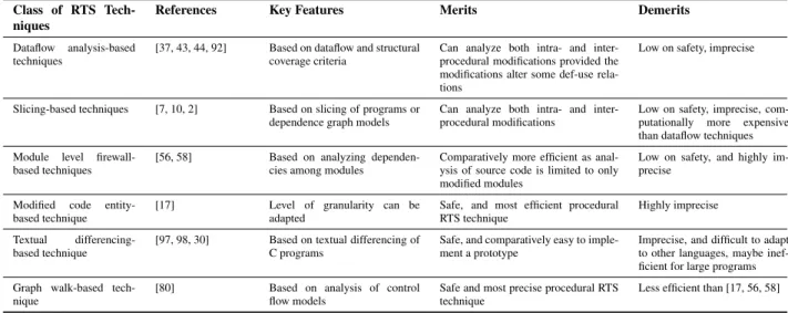
Class of RTS Tech-niques
References Key Features Merits Demerits
Dataflow analysis-based techniques
[37, 43, 44, 92] Based on dataflow and structural coverage criteria
Can analyze both intra- and inter-procedural modifications provided the modifications alter some def-use rela-tions
Low on safety, imprecise
Slicing-based techniques [7, 10, 2] Based on slicing of programs or dependence graph models
Can analyze both intra- and inter-procedural modifications
Low on safety, imprecise, com-putationally more expensive than dataflow techniques
Module level firewall-based techniques
[56, 58] Based on analyzing dependen-cies among modules
Comparatively more efficient as anal-ysis of source code is limited to only modified modules
Low on safety, and highly im-precise
Modified code entity-based technique
[17] Level of granularity can be adapted
Safe, and most efficient procedural RTS technique
Highly imprecise
Textual differencing-based technique
[97, 98, 30] Based on textual differencing of C programs
Safe, and comparatively easy to imple-ment a prototype
Imprecise, and difficult to adapt to other languages, maybe inef-ficient for large programs
Graph walk-based tech-nique
[80] Based on analysis of control flow models
Safe and most precise procedural RTS technique
Less efficient than [17, 56, 58]
Table 1: A comparison of RTS techniques for procedural programs.
procedures and hence cannot be applied for RTS of inter-procedural code modifications.
An important difference between graph walk and slicing-based techniques is that the latter uses dependence relation-ships to analyze the source code and identify the affected regions in the source code. Regression test selection is per-formed by monitoring the execution of the sliced region of code onT. On the other hand, the graph walk techniques use comparison of graph models of the program to identify the modifications [76, 80].
Table 1 summarizes the merits and demerits of the pro-cedural RTS techniques discussed in Section 3. In column 3, we highlight the key features of each class of techniques, and summarize the merits and demerits in columns 4 and 5.
4
RTS Techniques for
Object-Oriented Programs
The object-oriented paradigm is founded on several impor-tant concepts such as encapsulation, inheritance, polymor-phism, dynamic binding, etc. These concepts lead to com-plex relationships among various program elements, and make dependency analysis more difficult [104]. Moreover, in object-oriented development, reuse of existing libraries, class definitions, program executables (blackbox compo-nents), etc. are emphasized to facilitate faster development of applications. These libraries and components frequently undergo independent modifications to fix bugs and enhance functionalities. This creates a new dimension in regression testing of object-oriented programs that use these third-party components or libraries, since the source code for such libraries are often not available. These features, there-fore, raise challenging questions on how to effectively se-lect regression test cases that are safe for such programs [9, 68].
The reported RTS techniques for object-oriented pro-grams can broadly be classified into the following three major categories:
1. Firewall-based techniques [53, 47, 1, 48]
(a) Class firewall technique [53] (b) Method level firewall technique [48]
2. Program model-based techniques [77, 82, 41, 73] 3. Design model-based techniques [4, 27, 69, 33, 14]
In the following, we briefly review the different classes of RTS techniques that have been proposed for object-oriented programs.
4.1
Firewall-Based Techniques
Firewall-based RTS techniques for object-oriented pro-grams have been proposed by Kung et al. [53], Hsia et al. [47], Abdullah and White [1] and Jang et al. [48]. These techniques are based on the concept of a firewall defined originally by Leung and White [58] for procedural pro-grams. The firewall techniques aim to identify the affected classes for the modified version of the software. A firewall can be defined as the set of all the affected classes that need to be retested. These techniques select all test cases which exercise at least one class from within the firewall.
4.1.1 Kung’s Class Firewall Technique
anORDis annotated with the type of relationship (inheri-tance, association, aggregation) that exists between the end nodes associated with that edge. ABBDrepresents the in-terface and the control structure of a method of a class, and the relationship of a class with the other classes in the pro-gram. AnOSDis designed to capture the dynamic behavior of a class.
Changes to data items, methods and class definitions of the original program (if any) are identified by analyzing the three models corresponding to P andP′. The technique of Kung et al. [53] instrumentsP to collect information about which classes are exercised by which test cases. A class is potentially affected by a change to another class if it is either directly or indirectly related to the changed class through inheritance, aggregation or association rela-tionships. The firewall for a classC is computed as the set of classes that are directly or transitively dependent on C (by virtue of relations such as inheritance, aggregation or association) as described in anORD. When a classCis modified, the technique selects all the test cases that exer-cise one or more classes within the firewall forC.
Figure 10 shows an exampleORD(along with test cases) adapted from [90]. In the figure, a solid arrow from one class to another indicates that the two classes are related by inheritance, aggregation or association relationships. The boundary (denoted by the dashed line) around the classes A,B,CandDdepicts the firewall computed for classD. Whenever the classDis modified, classesA,BandCalso need to be regression tested for they belong to the set of classes which constitute the firewall for classD. In Figure 10, a solid line from a test case to a class indicates that the test case is used to test the class (e.g., test caseT C1is used to validate classesDandF). Thus according to the firewall technique, only test casesT C1andT C2should be executed again after classDis modified since they exercise those classes within the firewall forD.
B
A
D
C G
H
F
E
TC2
TC3
TC1
TC4
Figure 10: An exampleORDand the firewall for classD.
4.1.2 Method-level Firewall Technique
Jang et al. [48] have proposed a change impact analysis approach to select regression test cases for C++ programs. While a class and a statement are considered as the units of testing in [53] and [77], the technique reported in [48]
con-siders a method as the unit of retesting and aims to iden-tify all affected methods. The authors have identified cer-tain common types of modifications that are possible for a C++ program, and a method-level firewall is constructed for each modification to identify the impact of the changes.
4.1.3 Critical Evaluation
Firewall techniques are not safe because these techniques do not select test cases which may execute the affected modules from outside the firewall. These techniques are also imprecise since all test cases that execute a class in the firewall do not necessarily execute the affected parts of the code. For example, suppose that a class C is modi-fied. Let another classDcontain two methodsD::foo()
andD::bar(), of which the methodD::foo()invokes
the services provided by classC. Then, by the approach described in [53], classDis included in the firewall com-puted forC. Therefore, any test case which exercisesDis included in the regression test suite. However, there might be test cases which exercise only the methodD::bar()
and hence could have been omitted from the regression test suite. The firewall-based approaches are however computa-tionally more efficient and are preferred for RTS analysis of large programs. Moreover, the technique proposed in [48] is more efficient than [53] since this method aims to achieve a balance between the efficiency of class firewall-based technique [53], and the precision of more fine-grained ap-proaches like [77].
4.2
Program Model-Based Techniques
In the following, we discuss different RTS techniques [77, 73, 82, 41, 65] that have been proposed for object-oriented programs and are based on an analysis of program models for selecting regression test cases.
4.2.1 Technique Based on Class Dependence Graphs
ClDGmodels with each test case. Then, a technique simi-lar to [80] is used to select regression test cases.
4.2.2 Technique Based on Extended Control Flow for
C++
Rothermel et al. [82] have proposed an approach for RTS of C++ programs based on an analysis of the control flow representations of the original and the modified programs by extending the technique proposed in [80]. Since a CFGrepresents the control flow information of only a sin-gle method, the concepts of Inter-procedural Control Flow Graph (ICFG) and Class Control Flow Graph (CCFG) have been introduced to represent control flow of multi-function programs and object-oriented programs respectively. An ICF G for program P is composed of CFGs for each method inP. Each call site inPis represented by a pair of nodes calledcallandreturnnodes [82]. Eachcallnode is connected to the entry node of the called method by a call edge, and each exit node is connected to thereturnnode of the calling method by a return edge. AnICFGis used to model programs having a single entry point, whereas a class can have multiple entry points [82]. ACCFGis used to model classes, and consists of individual CFGs for all methods of a class. Given the graph models for the original and the modified programs, the RTS algorithm [82] extends the graph walk-based approach [80] to traverse the models and select relevant regression test cases.
4.2.3 Technique Based on Extended Control Flow for
Java
Harrold et al. were the first to develop a safe RTS tech-nique [41] for Java programs based on control flow analy-sis. Their technique is an adaptation of the graph walk tech-niques proposed in [80, 82], and can handle various object-oriented features such as inheritance, polymorphism, dy-namic binding and exception handling. Their method con-sists of three steps: constructing intermediate representa-tions for the source programs, analyzing the graphs and de-termining the set of dangerous edges, and test case selec-tion. Harrold et al. use aJIGrepresentation for modeling Java programs.
The twoJIGs constructed for the original and the modi-fied programs are simultaneously traversed (depth-first) to identify dangerous edges. Finally, based on the test cov-erage information obtained through code instrumentation, the technique selects test cases that exercise the dangerous edges identified during graph traversal.
4.2.4 Partition-Based Techniques
Partition-based techniques are motivated by the need to combine the effectiveness of precise but expensive RTS techniques with techniques that work at a higher-level of abstraction and are relatively imprecise.
Partition-Based RTS Technique for Java Programs:
Orso et al. have presented a novel two-phase partitioning approach for RTS of large Java programs [73]. Their tech-nique works in two phases, calledpartitioning and selec-tion. In the partitioning phase, the original and the modified programs are modeled as Interclass Relation Graphs (IRG) [73]. The twoIRGs are analyzed to identify hierarchical, aggregation, and use relationships among classes and inter-faces. Then, the set of classes and interfaces that have been changed are identified. The partition phase analyzes syn-tactical changes at thestatementlevel and thedeclaration level. A change at the statement level consists of addition, deletion or modification of program statements. A decla-ration level change means modifications in the decladecla-ration of the type of a variable, addition or deletion of a method, change in the modifier list of an existing method, etc. The class dependency information along with the changes is used to identify at an abstract level the affected parts of the code. The set of affected classes and interfaces identified from the first phase constitutes apartitionof the program.
In the selection phase, a more detailed analysis of the partitions are carried out. The selection phase builds JIG models representing the modified regions of code from the partitions. TheJIGmodels are then analyzed using the RTS technique proposed by Harrold and Rothermel in [80]. An edge-level test selection criterion is used to select test cases which execute the affected parts of code.
Partition-Based RTS Technique for C# Programs:
Mansour and Statieh [65] have proposed a two phase RTS technique targeted for the C# programs. Their RTS tech-nique first constructs an Affected Class Diagram (ACD) based on the changes made to the modified program. An ACDrepresents modifications made at the level of a class, an interface, web or window services, and COM+ compo-nents. Their technique then uses a test coverage criterion based on theACDto select a subset of test cases. AnACD models a program at a high level of abstraction. A more de-tailed analysis is then carried out by modeling the programs using C# Interclass Graphs (CIG). A C# Interclass Graph (CIG) is a control flow graph that captures all the affected methods in anACD. The technique constructsCIGmodels for the original and the modified programs, and regression test cases are selected based on the graph walk techniques [41, 82].
4.2.5 Critical Evaluation
in [82, 77] do not consider several other common features of object-oriented programs such as exception handling. These techniques [82, 77] can also be imprecise when test-ing affected polymorphic calls [41].
The techniques proposed in [41, 73] are safe RTS tech-niques for Java software, and are able to handle important object-oriented features of Java such as polymorphism, dy-namic binding and exceptions. These techniques use a dif-ferent method for capturing polymorphism than [82] which leads to a more precise selection of regression test cases. The two phase partition-based RTS technique proposed for Java programs [73] is comparatively more efficient than [41] because the analysis of the affected parts of the pro-gram is divided across two phases - a coarse-grained first phase and a more fine-grained second phase. This two-phased approach helps to limit the extent of code for which a minute low-level analysis is required.
Although the class firewall based technique [53] does not consider certain object-oriented features such as ex-ceptions, the technique can still be extended for selecting regression test cases for a subset of the Java program fea-tures. The advantages of the firewall techniques are that they are comparatively more efficient than the program model-based techniques [41, 73], and can be applied for RTS of large programs. However as already discussed, the firewall techniques are unsafe and are relatively less precise than the techniques reported in [41, 73].
Mansour and Statieh’s RTS technique [65] is a safe RTS technique tailored for C# programs. But the technique can be computationally expensive for large programs since the complexity of the algorithm is quadratic in the number of theCIGnodes.
4.3
Design Model-Based Techniques
Model-based testing of software has become very pop-ular with the advent of the model-driven development paradigm. In the model-driven development (MDD) paradigm, a design model is usually refined to obtain the code. The widespread use of CASE tools for object-oriented system development ensures a close correspon-dence between a design model and its code. Hence, design models can effectively be used for RTS analysis of object-oriented programs [15].
Unified Modeling Language (UML) [12] is an ISO stan-dard for representing analysis and design models of object-oriented programs. The following are some important ad-vantages of UML-based regression testing [26]:
– Traceability- It is easier to maintain traceability
be-tween the design artifacts and the test cases than main-taining traceability between code and the test cases. It is also easier to identify changes between across dif-ferent versions of design artifacts as compared to ana-lyzing changes across code versions [15, 14].
– Scalability - Code-based regression testing becomes
very expensive when applied to large programs. A
model being a simplified representation of a code, model-based testing is comparatively more efficient.
– Language independence- Different parts of a software
may be developed using different programming lan-guages. It, therefore, is difficult to design and im-plement an RTS technique which can take into ac-count parts developed using different programming languages during test case selection. A UML model-based RTS technique helps to overcome this short-coming since it is independent of the implementation [14].
We now briefly discuss few UML model-based RTS techniques [4, 27, 33, 14, 69] that have been proposed in the literature.
4.3.1 RTS Based on Class and Sequence Models
Ali et al. have proposed an RTS technique based on anal-ysis of UML class and sequence diagrams [4]. Their tech-nique analyzes class and sequence diagrams at the level of class attributes and operations. Concurrency in sequence diagrams is captured by the use of asynchronous messages and parallel instructions which cannot be adequately repre-sented by traditionalCFGmodels [32]. Therefore, an ex-tended control flow model called Concurrent Control Flow Graph (CCFG) has been introduced in [32]. Ali et al. ex-tends the model-based control flow analysis proposed by Garousi et al. in [32] for regression testing based on UML design models by also including information available from class diagrams. ACCFGmodel is constructed for each se-quence diagram. To model a sese-quence diagram invoking other sequence diagrams, the corresponding CCFGs are connected using control flow edges. The sequence and the corresponding class diagrams are analyzed and an extended concurrent control flow graph (ECCFG) is constructed to model the program. The information about which attributes of a class receive messages in a sequence diagram are de-rived from the corresponding class diagrams, and are rep-resented in the ECCFG. The pre- and post-conditions of a method are also represented in anECCFGby introduc-ing new nodes. The ECCFGmodels for the original and the modified version of the application are then analyzed to find out the changes between program versions. This information is used to select regression test cases.
4.3.2 RTS Based on Class and State Machine
Diagrams
![Figure 10 shows an example ORD (along with test cases) adapted from [90]. In the figure, a solid arrow from one class to another indicates that the two classes are related by inheritance, aggregation or association relationships](https://thumb-us.123doks.com/thumbv2/123dok_us/8043283.2129807/13.892.98.443.785.975/figure-indicates-classes-related-inheritance-aggregation-association-relationships.webp)


