Clinical Outcomes of Three Different Crown Systems using CAD/CAM Technology
Emily R. Batson, DDS
A thesis submitted to the faculty of the University of North Carolina at Chapel Hill in partial fulfillment of the requirements for the degree of Master of Science in the
School of Dentistry (Prosthodontics).
Chapel Hill 2013
Approved by:
Lyndon F. Cooper, DDS PhD
Terrence Donovan, DDS
ii © 2013
iii
Abstract
EMILY R. BATSON, DDS: Clinical Outcomes of Three Different Crown Systems using CAD/CAM Technology
(Under the direction of Lyndon F. Cooper DDS, PhD)
CAD/CAM technology has opened many doors for dental restoration
fabrication. Improvements in intraoral scanning technology and the use of newer
esthetic materials have brought many questions to the forefront. Concerns over
restoration fit and quality have been expressed, as well as accuracy of digital
methods involved for crown fabrication1. This clinical study examined three different crown materials for posterior teeth in need of full coverage restoration. Crown
preparations were scanned intraorally using the E4D or iTero scanner and crowns
digitally designed and fabricated. Teeth received porcelain fused to metal, lithium
disilicate or monolithic zirconia restorations. Gingival parameters and modified
USPHS criteria were recorded for each crown and marginal integrity was examined
using micro-CT analysis. An 18.8% rejection rate was noted for crowns due to poor
iv
ACKNOWLEDGEMENTS
To the residents of the Graduate Prosthodontics program for their support and assistance during this project.
To the staff and faculty of the University of North Carolina at Chapel Hill Graduate Prosthodontics program and the Department of Prosthodontics.
To Drs. Lyndon F. Cooper, Terrence Donovan, and Ibrahim Duqum for their assistance and guidance throughout this project.
To Align Technology, Inc. for assistance in use of their technology
To Microdental Laboratories, Mr. Lee Culp, and Mr. Jack Marrano for their help in fabrication of crown restorations.
To Dr. Ceib Phillips, Yunro Chung, PhD candidate Biostatics, and Dr. Roger Arce for assistance with the statistical analysis.
To Dr. Gustavo Mendonҫa and Kevin Guley for their assistance with Micro-CT analysis.
To the American Academy of Fixed Prosthodontics and Tylman Grant Committee for financial assistance of the project.
v
TABLE OF CONTENTS
LIST OF TABLES………vii
LIST OF FIGURES……….…viii
LIST OF ABBREVIATIONS………ix
Chapter 1. INTRODUCTION……….………...1
1.1 Benefits of CAD/CAM Technology………2
1.2 Limitations of CAD/CAM Technology………….………..3
1.3 Fit of Restorations……….………..4
1.4 Zirconia……….5
1.5 Lithium Disilicate………...………8
1.6 Rational for a clinical study using newer materials and CAD/CAM Technology………..9
2. MATERIALS AND METHODS………11
2.1 Study Design………...11
2.2 Visit 1 – Crown Preparation Treatment………..11
2.3 Crown Fabrication……….13
2.4 Visit 2 – Crown Insertion………...………..……….15
2.5 Visit 3 – One-month recall visit………17
2.6 Micro-CT Analysis………...………..17
vi
3. RESULTS……….….19
4. DISCUSSION………24
4.1 Gingival Parameters………..24
4.2 Modified USPHS Criteria……….………..25
4.3 Horizontal Marginal Discrepancy Values………27
4.4 Limitations of the Study……….………28
5. CONCLUSION………..30
APPENDICES……….31
Appendix A – Inclusion and Exclusion Criteria………31
Appendix B – Modified USPHS Criteria for Crown Evaluation………..32
vii
LIST OF TABLES
Table 2.1 - Modified USPHS Criteria for Crown Evaluation…….……….16
Table 3.1 - Modified USHPHS Criteria – Shade……….……….20
Table 3.2 - Modified USHPHS Criteria – Contour………..….20
Table 3.3 - Modified USHPHS Criteria – Marginal Adaptation……….…20
Table 3.4 - Modified USHPHS Criteria – Occlusion………21
Table 3.5 - Linear Mixed Models Test for Significance of GCF Volumes…………...21
Table 3.6 - Generalized Estimating Equations (GEE) Method for significance between variables……..……..………22
Table 3.7 -Descriptive Statistics for Horizontal Marginal Discrepancy………23
Table 3.8 - Pairwise Comparisons between crown systems……….………23
viii
LIST OF FIGURES
Figure 1 – Flow of Restoration Fabrication………....15
Figure 2 – Bleeding on Probing (%)………....22
ix
LIST OF ABBREVIATIONS
CAD/CAM….……Computer-Aided Design/Computer-Aided Manufacturing
PFM………..………Porcelain fused to metal
Zr………...………..Zirconia
BOP………..……….Bleeding on probing
GCF….……….Gingival crevicular fluid
Micro-CT………Micro-computed tomography
USPHS………….……….United States Public Health Service
Chapter 1 INTRODUCTION
CAD/CAM technology entered the dental arena almost thirty years ago, and has
seen a dramatic evolution of its capabilities throughout the past two decades.
CAD/CAM advancements have incorporated multiple types of dental restorations
including orthodontic appliances, implant prostheses and single or multiple tooth
restorations. Currently, there are numerous dental CAD /CAM systems available for
clinicians and laboratories, and the choices of design applications continue to
increase. Restorative dentistry has not only been affected by the infiltration of
CAD/CAM technology, but the advancement of esthetic materials for use with
CAD/CAM systems. All-ceramic materials have evolved alongside CAD/CAM
technology, as the demand for esthetic restorations continues to grow. Moreover,
the search for viable alternatives to expensive alloys has further contributed to the
evolution of newer materials. A recent survey on laboratory fabrication projections
for restorative materials estimates by the year 2017 all-ceramic materials will be
used to fabricate approximately 42% of crown and bridge restorations.2 This will
reflect a 20% increase over a ten-year span. Today two materials are dominating the
stage for esthetic restorations; zirconia and lithium disilicate. Furthermore, with the
advances in milling technology, dental practitioners can create an efficient mode of
restoration delivery using in-office fabrication methods. Concerns over the use of
2
studies involving the use of CAD/CAM generated restorations are sparse, in addition
to controlled clinical trials involving the use of newer materials.
1.1 Benefits of Intraoral CAD/CAM Technology.
Numerous benefits are mentioned from manufacturers of intraoral dental CAD/CAM
systems. These include increased efficiency in restoration production, increased
patient comfort due to elimination of impression materials, and in-office control of
restoration fabrication for systems utilizing milling technology. One important benefit
is an instant 3-dimensional chairside view to evaluate tooth preparations. This
benefit may become part of dental education as students and faculty continue to find
new evaluation methods to compare preparations to accepted standards.3 Clinicians benefit from the ability to evaluate tooth preparations chairside and make necessary
modifications prior to restoration fabrication. Theoretically this could lead to better
fitting and more esthetic restorations. Other benefits include multiple pathways to
lead to the final product or restoration. Following similar principles used in reverse
engineering, data acquisition takes place either intraorally by direct capture of a
prepared tooth, or extraorally from an impression or gypsum cast of a prepared
tooth. Many scanning softwares use the common Standard Triangulation Language
(STL) format for data files which can be incorporated into a CAD program for either
model fabrication or direct digital design of a restoration without a solid model.4
Following restoration design copings can be printed using Rapid-Prototype (RP)
technology or milled. Depending on the type of material and restoration, full-contour
3
1.2 Limitations of CAD/CAM Technology
Questions still remain unanswered in regards to the quality of digitally fabricated
dental prostheses and whether one CAD /CAM system shows superior results to
another. Early developers focused their efforts on creating single tooth restorations,
mainly inlays, onlays, and full coverage crowns.5 Optical scanning of an abutment
tooth was historically the limiting factor in obtaining a well-fitting restoration.6 The prepared tooth presents challenges for optical scanners and CAD software systems.
As discussed in a recent review by Miyazaki et al7 crown margins can be difficult to
capture with intraoral scanning not only because of their design, but their proximity
to gingival tissues, adjacent teeth, and sulcular fluids. In addition, prepared teeth
tend to show geometries that test the boundaries for optical scanners. Because of
these intraoral limitations, many practitioners continue to use conventional
impression techniques and allow dental laboratories to create restorations using
CAD software, and if necessary CAM for fabrication. In a recent study by Güth et al8 accuracy of digital models was examined using an in vitro set-up. The direct intraoral
capture of a prepared abutment showed more accuracy than the scanned polyether
impression or gypsum cast. Other studies have concluded no significant difference
between intraoral scanning, a scan of an impression, or gypsum cast.9,10 Factors to consider when choosing to use an intraoral scanning device include location of
restoration margins (ie. supragingival vs. subgingival), location of restoration
(mandibular vs. maxillary; posterior vs. anterior) and inclusion of internal
modifications (retentive grooves, slots, potential undercuts). The accuracy of a scan
4
technology for dental restorations. Scanning manufacturers continue to make
improvements in their technologies by designing smaller, lighter-weight scanners
that can capture fine detail quickly. Practitioners, however, are still required to use
careful and meticulous techniques when obtaining an intraoral scan. A dry field and
a clean, well-isolated tooth preparation are of utmost importance in obtaining an
accurate scan.
1.3 Fit of Restorations
The fit of dental restorations has been an historically controversial topic. Fit can have
many definitions in regards to appropriate adaptation of a restoration to the prepared
tooth as a whole, but more commonly fit often refers to the marginal adaptation.
Holmes et al stated that many different terms can be applied to describe the
marginal fit of a dental restoration including internal gap, vertical and horizontal
marginal gap, and under- or overextended margins.11 Although no published numeric standard value or definition has been agreed upon, the marginal fit, or
adaptation of a single tooth crown at the margin interface commonly gets noted as
50-100 microns as an acceptable value. In 1966, Christensen12 published clinically
acceptable ranges of marginal discrepancies from 2-119 microns for cast gold inlay
restorations, but the least acceptable occlusal margin was determined to be 39
microns. These figures were based on an in vitro study examining the gingival,
proximal and occlusal surfaces of inlays. Lofstrom and Barakat13 found marginal discrepancies ranging from 7-65 microns of cast gold crown restorations based on
5
microns before and after cementation of PFM restorations. Felton et al15 examined cast gold and PFM restorations retrospectively using SEM analysis and found an
average marginal discrepancy of 160 microns but a range from 5-430 microns. In
addition, this study found a relationship between the gingival index and marginal
discrepancy values.
CAD/CAM fabricated restorations have been found to have similar readings
for marginal discrepancies and fit. Many in vitro studies show average marginal
discrepancies ranging between 35-71 microns, and clinical studies showing
equivalent values using SEM analysis.9,16-18 A recent clinical study by Brawek et al19 reported mean marginal discrepancy values of 51 microns for veneered Zr crowns
fabricated using intraoral scanning techniques and digital fabrication. Sailer et al20, however, reported a recurrent caries rate of 21.6% in Zr based fixed dental
prostheses (FDPs) that were hand-designed but digitized and then milled.One may
conclude that even with the additional all-ceramic materials available today, marginal
discrepancies can be held to the same standards as traditional gold and PFM
technologies when using CAD/CAM systems.
1.4 Zirconia
In its elemental form Zirconium, or Zr, lies as the 40th element in the periodic table
and is a grayish-white transition metal. It is commercially available for many uses
including kitchen cutlery, gemstones, and in nuclear energy applications. In the
all-6
ceramic applications. The two most common ores of zirconium are zirconium silicate
(ZrSiO4), also known as zircon, and zirconium dioxide (ZrO2), or zirconia. In its unalloyed state and as with most of the transition metals, zirconia can have three
different forms that are temperature dependent. The monoclinic form (m) exists from
room temperature to ~1170 oC, the tetragonal form (t) from 1170oC-2370oC, and the
cubic (c) from 2370oC to the melting point of 2715o C.21 It is the tetragonal form that has gained the most interest for the dental industry, due to a phenomenon referred
to as transformation toughening. When stabilizing oxides, such as CaO, MgO, or
Y2O3 are added to the tetragonal phase and subsequently cooled, stress-induced cracking will occur due to volumetric expansion. As phase transformation from the
t-form to the m-t-form is occurring, crack propagation is halted under compressive
stresses.22 This leads to an increase in the mechanical properties of zirconium.
Flexural strength values of 1200 MPa are averaged and greater than 5 MPa fracture
toughness is achieved. These mechanical properties are what have drawn interest
from the medical and dental field. Three main types of zirconia are available for use
for dental applications; 3% mol yttrium cation-doped tetragonal zirconia polycrystals
(3Y-TZP), magnesium cation-doped partially stabilized zirconia (Mg-PSZ), and
zirconia-toughened alumina (ZTA).21 3Y-TZP is seen most commonly in dental applications but Mg-PSZ and ZTA exist as well. In addition to the different types of
zirconia available for dental applications, two different machining methods exist.
Presintered blocks of zirconia can be milled in what is considered the soft-state.
Sintering volume shrinkage between 25-35% is accounted for with the milling, and
7
method is referred to as hard-machining. This occurs with fully-sintered 3Y-TZP or
Mg-PSZ blocks and requires a more intensive milling process since the blocks are
already at their full hardness. As with all other dental materials drawbacks exist. For
zirconia, low temperature degradation (LTD) is a concern, as this phenomenon has
been documented to occur in the presence of water, leading to aging and surface
cracking.23 In addition, due to the inherent properties of zirconia, dental restorations are often quite opaque in nature and do not allow for light transmission. Much like
metal based restorations this can be overcome with proper porcelain addition
techniques. There have been studies showing high chipping rates of veneered
porcelain for zirconia based restorations, with some reporting between 15-25% of
fractured or chipped veneering porcelain 20, 24. Further research has led to a change in firing protocols such that the differences in coefficients of thermal expansion and
cooling are compensated for zirconia. Additional research has been conducted on
the type of stabilizer added to zirconium during the transformation toughening phase
with the intention of altering heating and cooling rates to coincide with those of the
veneering porcelain. Research, however, is inconclusive as to whether this will
decrease the incidence of veneer fracture. Because of the technical complications
involved with veneering zirconia, a monolithic zirconia restoration may appear to
resolve some of the problems. Research involving monolithic zirconia restorations is
8
1.5 Lithium Disilicate
Glass-based dental ceramics have shown changes in their formulations over the
past three decades in order to reach desired outcomes of high esthetics and good clinical performance. In the late 1980’s leucite was added as a reinforcement to
improve mechanical properties of glass-based ceramics. IPS Empress is an
example of a commonly used leucite-reinforced ceramic used for esthetic
restorations and shows flexural strength values of 120-180 MPa.25 More recently lithium disilicate crystals have been incorporated into dental glass ceramics and
show improved mechanical properties, such as flexural strength values nearing
350-400 MPa. Today, eMax CAD and eMax Press (Ivoclar, Vivadent) are two varieties of
lithium disilicate based ceramics that can be used to fabricate single and multiple
tooth restorations. In addition, CAD/CAM based systems aid in the fabrication of
these types of restorations, as blocks for CAM are distributed for many milling
apparatuses. As with most all-ceramic studies involving dental restorations, clinical
data is limited for newer materials because of the relatively short time these
materials have been in use. However, concerns about failure mechanisms for lithium
disilicate restorations are similar to other glass-based ceramics. Fasbinder et al26
reported a 100% survival rate of 62 eMax CAD crown restorations in 43 patients
over a two-year recall period. There was no incidence of crown fracture or chipping
reported, and relatively high alpha scores for color and marginal adaptation. A
94.8% 8-year survival rate was reported by Gehrt et al27 for 94 single tooth for veneered eMax Press restorations. Furthermore, Wolfart et al published 8- and
9
demonstrated and an 87.9% survival rate at 10-years.28,29 These results are comparable to published results for conventional metal-based FDPs.30 Although these results are promising, more long-term randomized clinical trials are needed to
determine survival and complication rates. In addition, concerns over placing
reinforced glass-based restorations in posterior teeth have been expressed. Of the
studies previously mentioned, both anterior and posterior teeth were included. The
manufacture currently recommends eMax Press and eMax CAD for anterior and
posterior single unit restorations, but for multiple tooth FPDs, eMax Press is
currently recommended only for anterior tooth replacement. Replacement of
posterior teeth with lithium disilicate restorations is currently not recommended by
the manufacture, as more long-term clinical studies are needed.
1.6 Rational for a clinical study using newer materials and CAD/CAM Technology
Although many in vitro studies have been conducted and published using newer
all-ceramic materials and various CAD/CAM systems, there lies a need for more clinical
studies examining variables that can affect restoration success. In vitro studies have
shown laboratory values for hardness and flexural strength however these results
cannot always be applied clinically. In vitro studies examining fit of restorations
demonstrate what theoretically should be possible in ideal clinical situations.
Long-term data cannot be extrapolated from these types of studies. This study focused on
the use of two newer all-ceramic materials in conjunction with an accepted control
10
impressions and CAD/CAM technology was used for restoration fabrication. The
primary aims of the study were to examine gingival response to crown restorations,
marginal discrepancy values, and restoration quality using modified United States
Chapter 2 MATERIALS AND METHODS
2.1Study Design
This was a prospective clinical study that included patients aged 18 – 70 who
required restoration of one or two posterior teeth. Approval was given by an
Institutional Review Board under the Office of Human Ethics at the University of
North Carolina at Chapel Hill (IRB 11-2099.) Patients were screened and included
based on the criteria listed in Appendix A. During the screening appointment,
medical history was reviewed, and all patients had a bitewing and periapical
radiograph exposed. For individuals meeting the selection criteria for treatment IRB
approved consent documents were signed. Qualifying teeth were randomized into
three restorative groups using computerized software prior to treatment. All
individuals followed an approved written protocol for treatment. Patients were asked
to be available for up to two years for recall appointments.
2.2.Visit 1 - Crown Preparation Treatment
Prior to any treatment performed baseline data measurements were made for tooth
shade, gingival crevicular fluid (GCF) volume and bleeding on probing (BOP). Tooth
shade was chosen using a Vita-Lumin Classic shade guide. GCF was collected
12
was used for measuring volume following manufacturer’s directions for use. BOP
was measured using a UNC-15 periodontal probe (Hu-Friedy, Chicago, IL). GCF
and BOP measurements were collected for each tooth assigned and a control tooth
on the contralateral side. For patients receiving two crowns on similar contralateral
teeth (e.g. mandibular first molars), a separate adjacent or opposing tooth was used
as the control tooth for measurements. Periopaper strips were inserted on buccal
and lingual sides of both treated and control teeth and values were recorded for
each area. BOP was recorded as either present or not present. Patients were
anesthetized using a local anesthetic (Lidocaine 2% w/ 1:100k epinephrine). A
polyvinylsiloxane (Regisil, Dentsply-Caulk, Milford, DE) quadrant impression was
made encompassing the tooth to be prepared. This was later used for fabrication of
a provisional restoration from a bis-acryl provisional material (Integrity Temporary
Crown and Bridge Material, Dentsply-Caulk). All crown preparations were prepared
by one of three calibrated operators. Teeth requiring a build-up for appropriate
resistance or retention form were treated with either an amalgam core (Sybralloy,
Kerr Dental, Orange, CA) or composite core (Comp-Core, Premier Dental, Plymouth
Meeting, PA) prior to crown preparation. All teeth were prepared using standard
recommended preparation guidelines and water-cooled diamond burs (Premier
Dental). Teeth were reduced 1.5-2.0mm occlusally, and 1.0-1.5mm axially with a
deep chamfer margin circumferentially. A total occlusal convergence angle of 10-16
degrees was attempted for each preparation. Gingival cord (Ultrapak, Ultradent,
South Jordan, Utah) was placed prior to final margination and scanning. When
13
sulcular fluid or bleeding prior to intraoral scanning. Following tooth preparation a
second gingival retraction cord was placed and allowed to sit for 10 minutes.
Following removal of the second gingival retraction cord teeth were scanned
according to the type of restoration assigned; PFM and Zr restorations were
assigned to the iTero scanner (Align Technology, Inc, San Jose, CA) and eMax
crowns were assigned to the E4D scanner (D4D Technologies, Richardson, TX).
Prior to scanning, one cord was removed. Scans were obtained according to
manufactures directions for each intraoral scanner. Once scanning was complete,
preparations were reviewed chairside using the scanned image, and if necessary,
adjustments were made and the tooth was rescanned. An intraocclusal record was
made using Virtual CADbite Registration material (Ivoclar Vivadent, Amherst, NY) for
teeth assigned to the eMax group. PFM and Zr crown intraocclusal scans were
made as directed by the iTero scanner. Once scanning was complete, all cords were
removed, and a provisional restoration was fabricated, polished, and cemented
using Temp-Bond (Kerr Dental). Patients were given post-operative instructions and
oral hygiene instructions prior to being dismissed.
2.3. Crown Fabrication
Figure 1 demonstrates the workflow once scans were obtained of prepared teeth.
PFM and Zr crown preparations scanned by the iTero scanner were sent
electronically to the imaging center for Align Technology, Inc., in San Jose, Costa
14
electronically when significant deviations were noted from the default margin. Once
the scanned images were cleaned and the marginal areas were trimmed by use of
computer software, images and Cadent models were sent to Microdental
Laboratories (Dublin, CA). Two dental laboratory technicians fabricated all PFM and
Zr crowns. Both PFM and Zr crowns were designed using 3Shape software
(3Shape, Copenhagen, Denmark). Die-space allowance was set at .030mm for Zr
crowns, and .040mm for PFM crowns. PFM copings were produced by
Rapid-Prototype printing using the Envisiontec Ultra 2 3-D printer (EnvisionTEC, Dearborn, MI). Printed copings were invested and cast using a high noble alloy followed by
application of porcelain (IPS d.Sign, In-Line Porcelain, Ivoclar-Vivadent, Schaan,
Lichtenstein). The Cadent models were used for porcelain application and to verify
interproximal contacts and marginal adaptation. Zr restorations were fabricated
using milling technology (Wieland Mini, Wieland Dental, Pforzheim, Germany). Intrinsically colored monolithic Zr blocks were milled in the “green-state” and then
sintered following manufacturers recommendations. If necessary, extrinsic stains
were added for characterization (Empress stains, Ivoclar-Vivadent).
eMax CAD crowns were fabricated within the Graduate Prosthodontics Clinic
at the University of North Carolina using design software within the E4D scanner.
Restorations were sent electronically to the E4D mill and eMax CAD blocks were
milled according to the selected shade. Default cement spacing settings of 0.10
mm were used. Following milling, sintering was completed following
manufacturer’s directions. Staining and glazing was completed using eMax stains
15
Figure 1. Flow of Restoration Fabrication
2.4 Visit 2 - Crown Insertion
Prior to crown insertion, one operator was calibrated for use of the modified USPHS
crown quality criteria as listed in Table 2.1. USPHS ratings were recorded during the
crown insertion appointment. Appendix A details specific characteristics for each
16
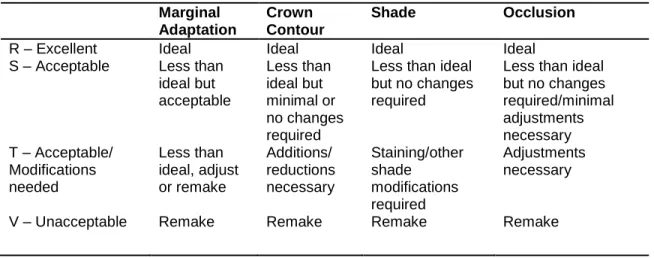
Table 2.1 Modified USPHS criteria for crown evaluation
Marginal Adaptation
Crown Contour
Shade Occlusion
R – Excellent Ideal Ideal Ideal Ideal
S – Acceptable Less than ideal but acceptable Less than ideal but minimal or no changes required
Less than ideal but no changes required
Less than ideal but no changes required/minimal adjustments necessary T – Acceptable/
Modifications needed Less than ideal, adjust or remake Additions/ reductions necessary Staining/other shade modifications required Adjustments necessary
V – Unacceptable Remake Remake Remake Remake
Provisional crowns were removed, and excess provisional cement was cleaned
from the treated tooth and gingiva. All crowns were fitted first by verifying
interproximal contacts. If necessary, excess contacts were adjusted using Dialite
porcelain polishing wheels (Brasseler, Savannah, GA). For crowns requiring addition
of an interproximal contact, all other fit parameters were verified first prior to adding
porcelain. For Zr and eMax crowns, black addition silicone was used to verify the fit
of the intaglio surface (Fit-Checker, GC America, Alsip, IL). White addition silicone
was used for PFM crowns (Fit-Checker, GC America). If necessary, internal
adjustments were made for PFM crowns using a carbide bur. Zr and eMax crowns
were adjusted by using a water-cooled fine diamond (Premier Dental). Margins were
verified by using explorer feel. Following internal fitting of the crowns, occlusion was
checked using occlusal indicating paper (Accufilm, Parkell Dental, Edgewood, NY). If
adjustments were necessary Dialite polishing wheels (Brasseler) were used. If
extensive adjustment was necessary, the crown was reglazed. Once seated, the
17
glass-ionomer cement (Ketac-Cem, 3M ESPE, St. Paul, MN). All excess cement
was cleaned, and post-operative instructions were given to patients.
2.5 Visit 3 - One-month recall visit
Patients were recalled at one-month post-cementation for GCF and BOP
measurements, and a polyvinylsiloxane impression of the cemented crown was
made for micro-CT analysis of crown contour. A small gingival retraction cord
(Ultrapak, Ultradent) was placed along the buccal margin prior to a light-body
impression material being placed and then covered with a heavy-body material in a
quadrant tray (Imprint 3, 3M ESPE). Photographs were made, and patients were
given instructions for oral hygiene.
2.6. Micro-CT analysis
Following the one-month recall visit, the quadrant PVS impressions were
sectioned through the buccal and occlusal surfaces of the impression as to include
only the buccal section of the treated tooth. Samples were sent to the Biomedical
Research Imaging Center (University of North Carolina, Chapel Hill, NC) for
scanning. All samples were scanned using a Scanco µCT 40 scanner (Scanco
Medical, Brüttisellen, Switzerland). Dicom files were created, and slices were
approximately 20 microns in width with approximately 6 microns of resolution.
18
Health, Bethesda, Maryland). Measurements of each crown were made at six
locations along the buccal margin, approximately 0.5-1.0 mm apart. Measurements
were made from the prepared crown margin of the tooth to closest horizontal point of
the crown restoration. Measurements were recorded as absolute values
representing overextended or underextended crown margins.
2.7 Statistical analysis
Statistical analysis was performed using computerized software (SAS, Cary, North
Carolina, USA). The Mantel Haenszel row mean score statistic was used to assess
an association between crown system and the modified USPHS criteria for
acceptable, thus the R, S and T values were combined for this analysis. Linear
mixed models were used for assessment of crown system and GCF volumes.
Generalized Estimated Equations (GEE) method was used for BOP analysis.
One-way ANOVA was used to determine significance with horizontal marginal
discrepancies between crown systems. For those showing significance pairwise comparisons were used between crown systems and scanners. Bonferoni’s method
Chapter 3 Results
A total of 32 crowns were fabricated for 22 patients. One patient received three
crowns (protocol deviation), seven patients received two crowns, and the remaining
14 patients received one crown. Six crowns were rejected for unacceptable marginal
adaptation and required refabrication. The remake rate due to unacceptable
marginal adaptation was 18.8%. Two of the remade restorations were done by
conventional techniques due to technical problems with the intraoral scanner used.
These crowns were left out of the micro-CT marginal analysis since CAD/CAM
techniques were not a part of the remake process. One eMax crown was fabricated
using a PVS impression due to technical complications with the E4D scanner. This
crown was fabricated using the same protocol for a Zr crown once the cast was
scanned using 3Shape software, and this is included in analysis for gingival
measurements and micro-CT analysis. Three patients did not return for the
one-month follow-up, and were excluded from statistical analysis for gingival
measurements, and horizontal marginal discrepancy values. One eMax crown was
cemented using Variolink II composite cement (Ivoclar-Vivadent) due to concerns
with thinness of the final restoration (approximately 1mm thick on occlusal portion).
There was no statistically significant association between crown type and
20
association between occlusion and Zr crowns (P=.0005). Tables 3.1 - 3.4 show the
distribution of USHPS criteria by crown system.
Table 3.1 Modified USPHS Criteria – Shade
Crown System
Modified USPHS Criteria – Shade
Unacceptable/ Rejected
Acceptable with modifications
Acceptable Excellent Total
PFM 0 2 6 4 12
Zr 0 6 3 1 10
eMax 0 1 9 0 10
Total 0 9 18 5 32
Table 3.2 Modified USPHS Criteria – Contour
Crown System
Modified USPHS Criteria – Contour
Unacceptable/ Rejected
Acceptable with modifications
Acceptable Excellent Total
PFM 0 2 7 3 12
Zr 0 0 9 1 10
eMax 0 3 7 0 10
Total 0 5 23 4 32
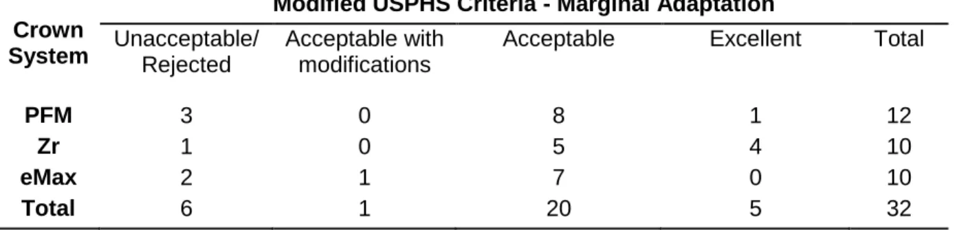
Table 3.3 Modified USPHS Criteria – Marginal Adaptation
Crown System
Modified USPHS Criteria - Marginal Adaptation
Unacceptable/ Rejected
Acceptable with modifications
Acceptable Excellent Total
PFM 3 0 8 1 12
Zr 1 0 5 4 10
eMax 2 1 7 0 10
21
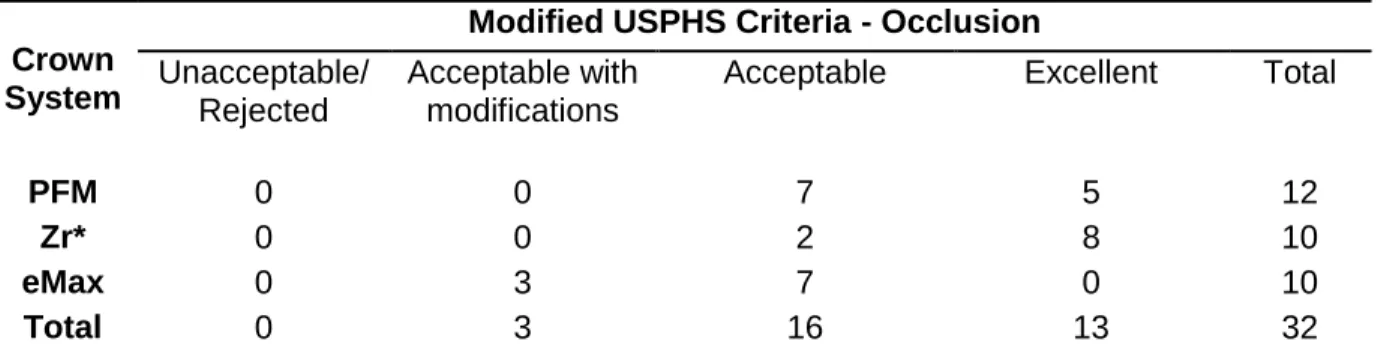
Table 3.4 Modified USPHS Criteria – Occlusion
Crown System
Modified USPHS Criteria - Occlusion
Unacceptable/ Rejected
Acceptable with modifications
Acceptable Excellent Total
PFM 0 0 7 5 12
Zr* 0 0 2 8 10
eMax 0 3 7 0 10
Total 0 3 16 13 32
(* denotes statistically significant values, Mantel Haenszel row mean score statistic)
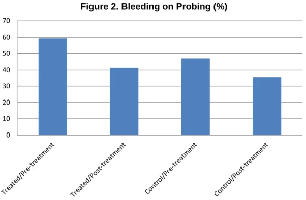
There were no statistically significant differences among the three crown systems for
GCF volumes or BOP. Tables 3.5, 3.6 and Figure 2 represent gingival parameter
measurements.
Table 3.5 Linear Mixed Models Test for Significance of GCF Volumes– P values
Buccal Surface
Lingual Surface
Crown System 0.2235 0.3810 Time of measure 0.4725 0.2136
Treated vs. Control
22
Table 3.6 Generalized Estimating Equations (GEE) Method for significance between variables for BOP
Variable p-value Crown System 0.9143 Time of Measure 0.0697 Tooth Status 0.1006
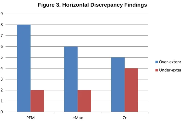
Since significance was shown (P=.003) using ANOVA, pairwise comparisons were
used to determine which systems were significant in regards to horizontal
discrepancy values. Only eMax vs. Zr showed statistical significance (P=.027).
Figure 3 and Tables 3.7 and 3.8 show descriptive statistics as well as pairwise
comparisons for horizontal discrepancy values. 0
10 20 30 40 50 60 70
23
Figure 3. Horizontal Discrepancy Findings
Table 3.7 Descriptive Statistics for Horizontal Marginal Discrepancy
Mean Horizontal Marginal
Discrepancy (µ)
S.D. Range (µ)
eMax 113.8 43.2 11.0-260.0
Zr 68.5 33.4 15.0-190.0
PFM 92.4 20.6 23.0-210.0
Table 3.8 Pairwise Comparisons between crown systems
Group 1 Group 2 F DF Adj P
eMax Zr 8.07 1 0.0270
eMax PFM 1.89 1 0.5445
Zr PFM 2.50 1 0.3798
0 1 2 3 4 5 6 7 8 9
PFM eMax Zr
Over-extended
Chapter 4 Discussion
4.1 Gingival Parameters
Many studies have indicated that the presence of a restoration near or below the
gingival margin may induce localized inflammation, and potentially lead to future
periodontal complications.15,31, 32 Gemalmez33 et al found significantly higher BOP readings for all-ceramic crowns with subgingival margins as compared to supra- or
equigingival margins. Al-Wahadni34 et al reported similar findings for 82 teeth that had received IPS Empress restorations. An increase in plaque index, gingival index
and pocket depths were found for restored teeth compared to a control teeth.
Although the data is short-term for this study, the analysis for GCF volume and the
presence of BOP in this study indicate there were no statistically significant
associations for any of the gingival parameters measured in regards to crown
system, time of measurement, or for the treated or control tooth. The null hypothesis
was accepted for this primary aim. Although there was an overall slight increase in
GCF volume for the lingual surfaces of treated teeth, it was not statistically
significant. It is worth noting that the frequency of BOP was less for both control and
treated teeth at the one-month reevaluation. This may be due to the Hawthorn effect
25
4.2 Modified USPHS Criteria
The null hypothesis was rejected for modified USPHS criteria since Zr crowns
showed statistical significance in regards to crown occlusion. Very few Zr crowns
required intraoral adjustment, which lends credibility to the accuracy of the intraoral
scan, the method of obtaining an intraocclusal record, and the digital design and
fabrication of the Zr restorations. The method of obtaining an intraocclusal record
differed for the iTero and E4D scanners. The iTero scanner allowed for direct
intraoral capture of the interarch relationship, while a PVS bite registration was made
and then scanned intraorally for the E4D system. There is a possibility for the bite
registration material to be inaccurate or move during the scan, as well as the digital
alignment of the bite registration to be mismatched by the clinician. Although not
statistically significant for any crown system, contour also reflects scan accuracy as
the detail of adjacent dentition needs to be replicated accurately for interproximal
contacts and overall crown contour to be correct. The majority of crowns (71.9%)
were acceptable with either minimal adjustments or no adjustments. Although
models were fabricated for crowns using the iTero scanner, only the PFMs required
the use of the model for actual design. Interestingly, only Zr and PFM crowns
received an excellent rating for the contour category while none of the eMax crowns
were rated excellent. This could be explained by the use of a model to verify
interproximal and occlusal contacts prior to crown seating. It could also be attributed to the clinician’s design of the eMax crowns as compared to the experienced
26
Shade did not show statistical significance in any crown system, but deserves
mention, as three times as many Zr crowns required custom staining as did PFMs.
This was necessary despite the different shades of 3Y-TZP blocks available for the
Zenostar system. Overall the eMax crowns showed the greatest shade acceptance
without changes being required. This has been noted in the literature, as Zr
restorations lack translucency and the ability to mimic a natural tooth shade and
often require veneering porcelain to obtain esthetic results.35
Marginal adaptation for the majority of crowns was satisfactory. There were
two PFM and one Zr crowns rejected early in the study prior to the operator marking
the margins with the iTero scanner before sending for electronic processing. Once
this process was done, there was only one other PFM rejected from the iTero
category. The technique used to determine whether marginal adaptation was
acceptable was by explorer feel. A bitewing radiograph was made for those
restorations showing questionable interproximal adaptation. Although it was not
specified what area of the margin deemed a crown unacceptable for statistical
analysis, it was noted clinically that five of the six crowns requiring refabrication had
discrepancies in an interproximal region. The interproximal regions and margins that
lie close to the gingival sulcus remain challenging for scanners to capture, and for
technicians to mark digitally. This is a limitation of using an intraoral scanning
system that does not allow for the clinician to perform the actual digital die-trim, but
instead relies upon a dental laboratory technician to read the scan and determine
margin placement. Additionally, limitations with explorer feel could have resulted in
27
horizontal discrepancies were more easily detected than vertical discrepancies for
clinicians using different diameter explorer tips. Moreover, Leknius et al37 showed different ranges of acceptability for dental students and experienced faculty
members during crown seating, with median threshold values ranging from 95-113
microns. It is possible that more crowns could have been considered unacceptable if
a new explorer of verified dimensions was used during crown evaluation and if more
than one examiner was used to verify crown adaptation.
4.3 Horizontal marginal discrepancy values.
The micro-CT data was somewhat difficult to manipulate in order to visualize a vertical “gap” for the majority of samples. It is theorized that due to the short time
(one-month) between cementation and impression, it is likely that many of the
vertical discrepancies were not detected because of cement within these regions.
However, differences in the overall horizontal contour of each crown system could
be measured consistently, and there was a significant difference between crowns
fabricated using the E4D system versus the iTero scanning system. Thus, the null
hypothesis was rejected for this aim. The use of a model for PFM and Zr crowns is a
possible explanation for this difference. eMax crowns were fabricated purely by
digital design and milling, thus there was no model involved. Likewise, Zr crowns
were digitally designed and milled, but finished on a solid model to verify contours. It
is possible that Zr crowns could be milled, and then adjusted or rejected if marginal
contour is inadequate. Another explanation lies with the type of mill that fabricated
28
diamonds to complete cutting of the eMax block. The Wieland mini-mill is a 4-axis
mill with five different milling tools in varying diameters, so it is possible the mill could better accommodate marginal areas that were less than a deep chamfer’s width, or
had uneven architecture. The type of cement for all of the restorations was the same
however the die spacing included in each crown type differed, so this could have
affected the fit of some restorations. In addition, the type of preparation design
deserves mention, as a deep chamfer margin was chosen. Other published literature
has mentioned the use of a modified or rounded shoulder as a better type of margin
design for all-ceramic restorations that will be of a milled-variety. Souza et al38 found statistically significant differences in vertical marginal discrepancies between three
margin designs using the CEREC system. The rounded shoulder design had a mean
value of 29.24 microns, while the titled chamfer had a mean value of 99.92 microns.
Baig et al18 showed higher marginal discrepancy values for milled restorations with both a deep chamfer and rounded shoulder margin design.
4.4 Limitations of the Study
Blinding of the practitioners could have been incorporated into this study to ensure
lack of bias with use of the intraoral scanners. In addition, a silicon replica of the
fitted crown prior to cementation could have enabled analysis of marginal
discrepancy values. Scanning electron microscopy might have been used to visualize and measure marginal discrepancies or “gaps” in a two-dimensional
manner. A single independent clinician to evaluate crowns at the time of insertion
29
values a control group of crowns that were fabricated using traditional methods could have been incorporated. The type of cement used is not the manufacturer’s
recommended cement for eMax crowns, but was chosen for consistency. This could
have affected marginal adaptation, as eMax crowns are recommended to be
cemented using a resin cement. The small sample size of this study may be difficult
to draw definitive conclusions, as well as the short time-span in which crowns were
evaluated. Long-term follow-up of subjects will help determine if there are
differences in gingival response to crowns systems, as well as the longevity of each
Chapter 5 Conclusion
Within the confines of this study, posterior single tooth restorations can be fabricated
using CAD/CAM technology in various fashions. There are multiple pathways that
can lead to the end result, and all or some of them can involve the use of CAD/CAM
technology. CAD/CAM designed restorations show similar ranges of acceptance
using modified USPHS criteria for marginal adaptation, shade, contour, and
occlusion. In this study it was shown that occlusion for the Zr crowns was
significantly better than the other crown types, and required less adjustments overall.
In addition, crowns fabricated from a scan that allows production and use of a solid
model showed statistically significant differences in regards to horizontal marginal
discrepancy values. Intraoral scanning devices and digital design workflow that
31
APPENDIX A
Inclusion Criteria Exclusion Criteria
a. Provision of written informed consent
a. Untreated rampant caries and uncontrolled periodontal disease
b. Age 18-70 years b. Absence of opposing dentition
c. Good physical and mental health c. Known pregnancy at time of inclusion
d. In need of one or two crowns to repair damaged or carious teeth
d. Present alcohol or drug abuse
e. A minimum of 20 teeth with stable intraocclusal contacts
e. Any systemic/local disease or condition that would prevent standard dental therapy using local anesthetic
f. Willing to return for 6 and 12 month recall visits
f. Known allergy to any restorative materials used in this study
g. Available contra-lateral, minimally restored or non-restored tooth to serve as control
g. History of presence of disease that could affect outcome of study
h. Mesial and/or distal tooth with proximal contact, and opposing tooth with occlusal contact
h. Study tooth may not serve as abutment for a removable partial denture
i. Presence of periodontal or pulpal disease for the study tooth or control tooth
j. Unlikely to be able to comply with study procedures according to Investigators
k. Unable or unwilling to return for follow-up visits for a period of 2 years
32
APPENDIX B Modified USPHS/CDA criteria – Marginal Adaptation
R – Excellent/Ideal – Explorer does not catch; continuous adaptation and indistinguishable margins
S - Acceptable – Explorer detects but cannot penetrate marginal area
T – Acceptable w/ modifications – Explorer detectable and penetrates marginal area
V – Unacceptable – Explorer detectable, gross marginal discrepancies upon explorer examination
Modified USPHS/CDA criteria –Crown Contour
R – Excellent/Ideal – contour follows normal physiologic tooth contour with no adjustments needed
S – Acceptable – slightly under/overcontoured; no modifications needed
T – Acceptable w/ modifications – restoration requires significant addition or removal of structure for function (contact addition or contact reduction, recontouring)
V – Unacceptable – restoration is undercontoured/overcontoured such that remake is necessary
Modified USPHS/CDA criteria – Color/Surface
R – Excellent/Ideal – restoration matches and complements existing dentition harmoniously
S – Acceptable – restoration closely matches surrounding dentition, slight shade difference
T – Acceptable w/ modifications– restoration requires addition of surface staining to meet acceptable shade match
V – Unacceptable – restoration requires remake in order to meet esthetic requirements
Modified USPHS/CDA criteria – Occlusion
R – Excellent/Ideal – restoration demonstrates ideal, harmonious relationship with existing occlusal scheme
S – Acceptable – restoration demonstrates adequate occlusal anatomy and function, but less than ideal; minor adjustments may be necessary
T – Acceptable w/ modifications– restoration requires addition or elimination of occlusal contacts
33
REFERENCES
1. Kelly, J. Developing meaningful systematic review of CAD/CAM reconstructions and fiber-reinforced composites. Clin Oral Imp Res 2007; 18S: 205-217.
2. From the website idataresearch.net; iData Research Inc. 2011.U.S. Dental Prosthetics and CAD/CAM Devices Market.
3. Renne W et al. E4D Compare Software: An alternative to faculty grading in dental education. J Dent Educ 2013; 77: 168-175.
4. Wang, W. Reverse Engineering:Technology for Reinvention. 2010. Chapter 2, pp.35-52.
5. Duret F, Preston J. CAD/CAM imaging in dentistry. Curr Opin Dent 1991; 1:150-154.
6. Mörmann WH, Brandestini M, Lutz F, Barbakow F. Chairside computer-aided direct ceramic inlays. Quintessence Int 1989; 20:329-339.
7. Miyazaki T, Hotta Y, Kunii J, Kuriyama S, Tamaki Y. A review of dental
CAD/CAM: current status and future perspectives from 20 years of experience. Dent Mat Journal 2009; 28: 44-56.
8. Güth JF, Keul C, Stimmelmayr M, Beuer F, Edelhoff D. Accuracy of digital models obtained by direct and indirect data capturing. Clin Oral Invest 2012;16.
9. da Costa JB, Pelogia F, Hagedorn B, Ferracane JL. Evaluation of different methods of optical impression making on the marginal gap of onlays created with CEREC 3D. Oper Dent 2010; 35:324-239.
10. Kokubo Y, Tsumita M, Sakurai S, Suzuki Y, Tokiniwa Y, Fukushima S. Five-year clinical evaluation of In-Ceram crowns fabricated using GN-I (CAD/CAM) system. J Oral Rehabil 2011; 38:601-607.
11. Holmes JR, Bayne S, Holland G, Sulik W. Considerations in measurement of marginal fit. J Prosthet Dent 1989; 62:405-408.
12. Christensen GJ. Marginal fit of gold inlay castings. J Prosthet Dent 1966; 16:297-305.
13. Lofstrom L, Barakat M. Scanning electron microscopic evaluation of clinically cemented cast gold restorations. J Prosthet Dent 1989; 61:664-669.
34
15. Felton D , Kanoy BE, Bayne SC, Wirthman GP. Effect of in vivo crown margin discrepancies on periodontal health. J Pros Dent 1991; 65: 357-64.
16. Biscaro L, Bonfiglioli R, Soattin M, Vigolo P. An in vivo evaluation of fit of zirconium-oxide based ceramic single crowns, generated with two CAD/CAM systems, in comparison to metal ceramic single crowns. J Prosthodont 2013; 22: 36-41.
17. Syrek A, Reich G, Ranftl D, Klein C, Cerny B, Brodesser J. Clinical evaluation of all-ceramic crowns fabricated from intraoral digital impressions based on the principle of active wavefront sampling. J Dent 2010; 38:553-559.
18. Baig M, Tan K, Nicholls J. Evaluation of the marginal fit of a zirconia ceramic computer-aided machined (CAM) crown system. J Prosthet Dent 2010; 104:216-227.
19. Brawek P, Wolfart S, Endres L, Kirsten A, Reich S. The clinical accuracy of single crowns exclusively fabricated by digital workflow – the comparison of two systems. Clin Oral Invest 2013; epub ahead of print.
20. Sailer I, Feher A, Filser F, Gauckler L, Luthy H, Hämmerle C. Five-year clinical results of zirconia frameworks for posterior fixed partial dentures. Int J
Prosthodont 2007; 20: 383-388.
21. Denry I, Kelly JR. State of the art of zirconia for dental applications. Dent Mater 2008; 24: 299-307.
22. Hannink R, Kelly P, Muddle B. Transformation toughening in zirconia-containing ceramics. J Am Ceram Soc 2000; 83: 461.487.
23. Lughi V, Sergo V. Low temperature degradation-aging of zirconia: a critical review of the relevant aspects in dentistry. Dent Mat 2010; 26: 807-820.
24. Raigrodski A et al. The efficacy of posterior three-unit zirconium-oxide-based ceramic fixed partial dental prostheses: A prospective clinical pilot study. J Prosthet Dent 2006; 96: 237-44.
25. Guess P, Schultheis S, Bonfante E, Coehlo P, Ferencz J, Silva N. All-ceramic systems: clinical and laboratory performance. Dent Clin North Am 2011; 55: 333-352.
35
27. Gehrt M, Wolfart S, Rafai N, Reich S, Edelhoff D. Clinical results of
lithium-disilicate crowns after up to 9 years of service. Clin Oral Invest 2013; 17: 275-84.
28. Wolfart S, Eschbach S, Scherrer S, Kern M. Clinical outcome of three-unit lithium disilicate glass-ceramic fixed dental prostheses: up to 8-year results. Dent Mat 2009; 25: e63-e71.
29. Kern, M, Sasse M, Wolfart S. Ten-year outcome of three-unit fixed dental prostheses made from monolithic lithium disilicate ceramic. J Am Dent Assoc 2012; 143: 234-240.
30. Pjetursson B, Brägger U, Lang N, Zwahlen M. Comparison of survival and complication rates of tooth-supported fixed dental prostheses (FDPs) and
implant-supported FDPs and single crowns (SCs). Clin Oral Impl Res 2007; 18S: 97-113.
31. Sorenson J. A rationale for comparison of plaque-retaining properties of crown systems. J Prosthet Dent 1989; 62: 264-269.
32. Youdelis R, Weaver J, Sapkos S. Facial and lingual contours of artificial complete crown restorations and their effects on the periodontium. J Prosthet Dent 1973; 29: 61-66.
33. Gemalmez D, Ergin S. Clinical evaluation of all-ceramic crowns. J Prosthet Dent 2002; 87: 189-96.
34. Al-Wahadni A, Mansour Y, Khader Y. Periodontal response to all-ceramic crowns (IPS Empress) in general practice. Int J Dent Hygiene 2006; 4: 41-46.
35. Raigrodski A. Contemporary materials and technologies for all-ceramic fixed partial dentures: A review of the literature. J Prosthet Dent 2004; 92: 557-562.
36. Hayazaki M, Wilson, N, Ebisu S, Watts D. Influence of explorer tip diameter in identifying restoration margin discrepancies. J Dent 2005; 33:669-674.
37. Leknius C, Giusti L, Chambers D, Hong C. Effects of clinical experience and explorer type on judged crown margin acceptability. J Prosthodont 2009; 19: 138-143.