0 INTRODUCTION
Pneumatic actuation systems have been extensively utilized in high technology and complex industries, such as the semiconductor manufacturing process, for precise positioning to isolate vibration. A key element in the pneumatic control system is electro-pneumatic valve which not only converts the electrical signal to pneumatic one but also constructs a close-loop for control system; therefore, its structure and parameters play an important role to reach a necessary performance. Many research works have been conducted to increase the efficiency of pneumatic control systems through improved design and development of pneumatic valves with a new structure and improved dynamic characteristics. A new pneumatic valve that benefits from a piezoelectric actuator was developed to increase dynamic properties and reduce energy consumption [1]. In [2] a pneumatic positioner with a piezoelectric actuator was modeled, and its advantages were introduced. A pneumatic servo valve driven by a piezoelectric actuator with a simple amplification mechanism was presented in [3]. In contrast, some other research works have attempted
to attain a reasonable and detailed mathematical model of the valve to optimize the control effort of the pneumatic system. Richer and Hurmuzlu [4] developed detailed mathematical models for each element of a pneumatic system to control the output of the actuator accurately. Wang et al. [5] made a new model for a nozzle-flapper (NF) valve to decrease the output thrust effect of the nozzle on the flapper. One of the effective structures in control valves is the NF mechanism, which can be used for obtaining quick response and precise control action due to its simple structure with high sensitivity and wide frequency range; many research works are being focused on studying and profiting from its advantages in the new structures of the fluid power valves. Kawashima et al. [6] designed and manufactured a new NF valve to minimize noise level and pressure fluctuations in the output flow of the valve. There have also been some research works that studied NF valves numerically to optimize their dimensional features [7] or suggested new structures to decrease detrimental effects of the output flow on it [8]. The load chamber is one of the main subdivisions of the NF valve, and its dynamics have an important role in the whole dynamic of the
Study on the Performance and Control of a Piezo-Actuated
Nozzle-Flapper Valve with an Isothermal Chamber
Kamali, M. – Jazayeri, S.A. – Najafi, F. – Kawashima, K. – Kagawa, T.Mohammadreza Kamali1,* – Seyed Ali Jazayeri1 –Farid Najafi2 – Kenji Kawashima3– Toshiharu Kagawa4
1 K. N. Toosi University of Technology, Faculty of Mechanical Engineering, Iran 2 University of Guilan, Engineering Faculty, Iran
3 Tokyo Medical and Dental University, Institute of Biomaterials and Bioengineering, Japan 4 Tokyo Institute of Technology, Japan
A new integrated nozzle-flapper valve equipped with a piezoelectric actuator and an isothermal chamber has been developed and studied in detail. The designed single stage valve controls the pressure and flow rate simply, effectively, and separately. This idea can easily be used in the pilot stage of a two-stage valve as well. Application of isothermal condition in the valve load chamber eliminates the dynamic malfunction that may persist from temperature variation within the valve load chamber; consequently, the governing equations for the prediction of pressure dynamics in the chamber are much more accurate and simpler. The valve has been equipped with a stacked type piezoelectric actuator which has a unique behaviour. Furthermore, stiffness, in the selected actuator, is enhanced against the thrust of the discharging flow from the nozzle, thus decreasing the complexity of dynamic equations of the valve. A detail mathematical model and simulation was developed to study the dynamic performance analysis of the proposed valve. An experimental test rig was built to validate the results of simulations. The unique features and performance of the proposed valve were studied thoroughly. The valve’s governing equations are nonlinear in nature, and some variables of the equations are a source of some uncertainties; sliding mode approach was used to control the steady and unsteady pressure and output flow rate of the valve.
Keywords: nozzle-flapper (NF) valve, isothermal chamber, piezoelectric actuator, sliding mode approach
Highlights
• A new nozzle-flapper valve was designed and manufactured. • Its dynamics were improved using an isothermal chamber.
• A stacked piezoelectric actuator was utilized to actuate the proposed valve.
valve. The lack of an accurate model for the state change of air in the load chamber of the NF valve makes the control of the system rather difficult. The state change model of the pressurized air in the load chamber is usually assumed as adiabatic or isothermal [9]. Realization of the isothermal condition in the load chamber makes the mathematical models of the NF valve simpler and improves its heat transfer criteria and dynamic characteristics. Therefore, implementing an isothermal condition in the load chamber of the valve facilitates its control. In other words, through only one pressure sensor, installed on the valve’s load chamber, both pressure or flow rate can be controlled more easily [10]. Kawashima et al. [11] proposed a new method to measure the unsteady flow rate of pressurized air using an isothermal chamber. Using benefits of such a chamber, Kawashima et al. [12] presented a system to determine the characteristics of the pneumatic solenoid valves. In the following of [12], Wang et al. [13] developed the same system in a way that it was possible to determine the characteristics for electrically modulated pneumatic control valves using an isothermal chamber.
Traditional NF valves use electromagnetic transducers to drive the flapper. However, this has shortcoming such as large dimensions, high electrical power consumption, slow response and susceptible to electromagnetic interference [3]. The most effective actuator that can overcome these limitations is a piezoelectric actuator. The unique properties of piezoelectric actuator make it the most appropriate choice for cases such as hazardous and sensitive industrial or medical environments. Piezoelectric actuators have much less electrical energy consumption along with much faster response time; also, the mechanism is spark- and magnetic-field free. These unique properties have made it much more applicable to be used as an actuator in pneumatic valves [1] to [3]. Furthermore, the stacked type of piezoelectric actuator simplifies the mathematical model of the valve due to its sturdy construction [5].
In this study, a detailed description of a new NF mechanism with isothermal load chamber and piezoelectric actuator is introduced. The proposed valve profits from both the isothermal load chamber and the piezoelectric actuator to simply, precisely, and effectively control the pressure or flow rate of the air without any concerns that may exist even in hazardous industrial environments. The theoretical analysis of the valve was developed to derive a more precise mathematical and simulation model. The static and dynamic performance of the proposed valve was assessed experimentally in order to validate the
developed model and to highlight the advantages of the proposed valve. Due to the nonlinear behaviour of the proposed valve and existence of uncertainties in some variables of the valve’s equations, sliding mode approaches have been designed and implemented to control the output flow rate and pressure of the proposed valve more precisely. Experimental data showed the effectiveness of the new NF valve; extended measurements were also carried out using steady and unsteady oscillatory output flow rate or pressure of the valve to prove its effectiveness.
1 PROPOSED VALVE
1.1 NF Mechanism
A schematic drawing of the proposed NF system is shown in Fig. 1, which consists of two fixed flow restrictors ((a) and (f)), a nozzle (d), a load chamber (c), and a piezoelectric actuator set that moves a flapper (e). Pressure-regulated air is delivered to orifice (a) and the variable flow restrictor (d) connected in series. The variable flow restrictor is made possible by moving the flapper that changes the distance Xn between the nozzle head and the flapper.
The flow rate through the nozzle and output orifice (f) is controlled by the distance between the flapper and nozzle. This would cause pressure changes of pb in
the load chamber, which is usually referred as nozzle back-pressure.
Fig. 1. Layout of the proposed NF system; (a) input orifice, (b) pressure sensor, (c) isothermal load chamber, (d) nozzle, (e)
piezoelectric actuator and flapper, (f) output orifice
have proved the effectiveness of such systems in their research [10] to [13].
When pressurized air is ejected from the nozzle, flow force is exerted on the flapper. Wang et al. studied flow force effects on the moving flapper that improve the control performance, but dynamic analysis of a standard NF valve is far more complicated [5]. In proposed piezoelectric actuator, the flapper becomes sturdier by the flow forces so that there is no need to model its displacement in dynamic equations.
1.2 Piezoelectric Actuator
Piezoelectric actuators convert electrical energy directly into mechanical energy. There are no moving parts to limit their resolution and mechanical performance. As shown in Fig. 2, there are two major types of piezoelectric actuator arrangements. These are either bending transducer or stacking transducer [14].
Fig. 2. Different piezoelectric actuators, stacked and bending transducer
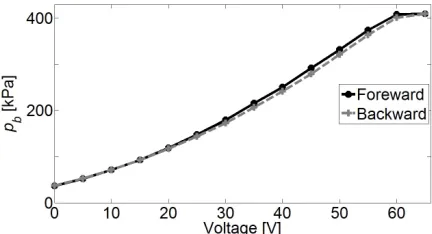
Figs. 3 and 4 illustrate a typical hysteresis characteristic of stacked and bending piezoelectric transducer, respectively. The rigidity of stacked piezoelectric actuator improves the hysteresis criteria and, due to lower deflection, the control pressure that is produced within the load chamber of NF mechanisms for the same supply pressure will be much higher.
Fig. 3. Hysteresis behaviour of stacked type piezoelectric actuator
Faster response is one of the main characteristic features of stacked type piezoelectric actuators. This
characteristic is especially advantageous in actuating pneumatic valves. The stacked type piezoelectric actuator utilized in the proposed valve can reach its nominal displacement in approximately one third of the period at the resonant frequency, based on its specification in [15], which was also verified here.
Fig. 4. Hysteresis behaviour of bending-type piezoelectric actuator
The dynamic behaviour of a flapper equipped with a piezoelectric actuator, which has a very fast response, has a minor effect on the overall dynamic response of the NF mechanism; therefore, the dynamics of the flapper can be neglected.
1.3 Dynamic Model of an NF Mechanism with Isothermal Load Chamber
Using state equation for pressurized air within the load chamber is shown in Fig. 1
p R
V W
b = b
θ , (1)
where pb denotes the load chamber’s absolute
pressure, R is the gas constant, θb is the load
chamber temperature, W is mass of the air in the load chamber and V denotes the load chamber volume. Differentiating above equation with respect to time t:
dp dt
R V
dW dt
RW V
d dt
b = θb ⋅ + ⋅ θb. (2)
Using continuity equation for air in the load chamber:
dW
dt =G G G1− 2− 3, (3)
where, G is mass flow rate through orifices. Using above governing equations:
dp dt
R
V G G G
RW V
d dt
b = θb.
(
− −)
+ . θb.Since during charge and discharge, the state of air in the load chamber is assumed to be isothermal, the above equation can be simplified:
dp dt
R
V G G G
b = θb.
(
− −)
.1 2 3 (5)
For the isothermal chamber, the average temperature is assumed to be equal to the room temperature [10]. It is concluded from Eq. (5) that for a fixed chamber volume of V and the room temperature of θb, an instantaneous desired mass flow rate G2
could be produced by controlling solely the pressure changes. The mass flow rate G is easily converted to volumetric flow rate Q under standard conditions:
Q G= /ρ, (6)
where ρ is pressurized air density.
The compressed air flow rate through fixed or variable orifices could be either sonic or subsonic depending upon the upstream/downstream pressure ratio [16]. The mass flow rate through a restriction is a function of geometric parameters, the upstream and downstream pressures. Therefore, mass flow rates, G1, G2, and G3 are calculated as follows:
G
Cp p
p b
Cp
p p b =
≤
− −
−
ρ
θ
ρ
θ
0 1 1
2 1
0 1 1
2 1
2
293
293 1
1
1
; if
; i
. ff
,
p p21 b
>
(7)
where coefficient C is the sonic conductance, which represents the flow’s passing ability, and is represented by C = Se / 5 where Se is effective area of
orifices or nozzle and b is the critical pressure ratio. If G is calculated for input orifice then p1=ps and
p2=pb, but if G is calculated for output orifice and
nozzle then p1=pb and p2=pa.
1.4 Simulation Program
A simulation model based on the above analysis is established and shown in Fig. 5. The input is the flapper displacement of Xn, while the outputs are the
control pressure pb, and the flow rate Q. According to
the reasoning mentioned earlier, the dynamic response of the piezoelectric actuator has a minor effect and is not taken into account.
To validate the valve performance and developed model, a MATLAB/SIMULINK model of the system
as shown in Fig. 5 was constructed. Some experiments were carried out to determine the parameters of the developed model, which included the effective area coefficients of the orifices and nozzle, as well as the critical pressure ratio. Through comparison of simulation results and experimental data, the selected mentioned parameters are optimized. The effective area coefficients of the NF valve were chosen as 0.86 for input and output orifices and 1.0 for the variable orifice. The best critical pressure for designed structure is derived to be 0.53.
Fig. 5. Simulation model for the proposed valve
1.5 Experimental Setup and Results
An experimental test rig, shown in Fig. 6 for NF mechanism was designed and manufactured to validate the developed simulation model and prove the effectiveness of the proposed valve.
Fig. 6. Developed NF mechanism layout
Table 1. Main parameters of the valve
Symbol Description Value
Doi Diameter of the input orifice 0.4 mm
Doo Diameter of the output orifice 0.3 mm
V Volume of the load chamber 0.7 cm3
Xn Displacement domain of the piezoelectric actuator 0 mm to 0.09 mm
A pressure regulator was used to stabilize the air supply. Stabilized air is fed to the proposed valve through the input orifice. The dimensions of the main subdivisions of the proposed valve have been presented in Table 1. They were estimated using the simulation model before manufacturing the proposed valve and were estimated based on required output flow rate and dynamic behaviour.
The load chamber of the valve was filled with copper wire of 50×10–3 cm diameter. Compact mass density was greater than 300 kg·m–3. These circumstances fulfil the isothermal condition in the load chamber [10]. The utilized piezoelectric actuator in the proposed valve is specified with part number P-841.6 and is produced by Physik Instrumente. The control approach was developed and implemented in a MATLAB/SIMULINK environment. Digitally generated control signals using a MATLAB/Real-Time Workshop environment with a CSI-360116 data acquisition board (made by Interface) were used to drive the piezoelectric actuator through a power amplifier. A semi-conductive-type pressure sensor was used to measure the pressure of the isothermal chamber. The output flow rate is derived from Eq. (3) by differentiating the pressure; five sets of data were used for this purpose. A low-pass filter was used to smooth out the pressure curve. The cut-off frequency of the filter was 2.5 times greater than that of the input frequency. Tests were performed at a constant ambient temperature of 20 °C and supply air pressure of 400 kPa.
1.5.1 Results to Compare Isothermal and Conventional Settings
Initially, some tests were carried out to show the effectiveness of the suggested isothermal chamber in comparison to the conventional chamber, which is a chamber without any metal wool for the setup, even though many previous studies had already shown its effectiveness [10] to [13]. The chamber volume was selected as 29.5 cm³.
The isothermal chamber temperature fluctuation is shown in Fig. 7 for simulation results and experimental data. The input voltage to the piezoelectric actuator was [45 – 44.5 × sin(2πf·t)] V. Using the stop method [11], the average temperature in the chamber was measured. The ambient temperature was 293 K in the test room. The frequency was 20 Hz. The experimental data are shown by dark points, and the solid line represents the simulation results. The temperature deviation is about 2 K, which suggests
that isothermal condition by metal wool in the chamber is well established.
Fig. 7. Temperature variation in the valve load chamber
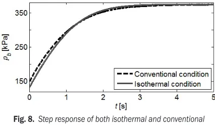
The step response of isothermal and conventional chambers is shown in Fig. 8. Initially, the distance between the flapper and head of the nozzle was at the upper limit and suddenly was reduced to zero. The response for isothermal chamber became faster due to both volume decrease and heat transfer effects. The pressure drop at the beginning of the figure in the isothermal case is due to utilization of copper wire in the load chamber.
Fig. 8. Step response of both isothermal and conventional chambers
1.5.2 Performance of the Proposed Valve
For the proposed valve, the static behaviour of the simulation model and experimental data are shown in Fig. 9. The steady- state control pressure pb was
plotted against the input displacement of the flapper Xn. Using the laser displacement measurement unit
Acuity AR700-0125, Xn was measured precisely.
Excellent agreement between simulation model and experimental data is observed despite some small differences which are thought to be due to the uncertainty in the volume of the load chamber and measurement of ambient temperature θb. There
is almost a linear relationship between the input displacement and steady state pressure of the load chamber when Xn varies within the small range of
0.018 mm to 0.075 mm displacement.
Fig. 9. Static behaviour of the valve compared with simulation model
Fig. 10. Step response of the proposed valve
The dynamic response of the proposed valve is analysed using step and frequency responses. As illustrated in Fig. 10, the step response of the isothermal chamber for the proposed valve validates the mathematical model and simulation results. From Fig. 10, it can easily be concluded that there is no significant delay in pressure response of the proposed valve. The response time of the designed valve is about 2.5 ms, so the proposed valve can be classified as a fast switching valve. Therefore, it can be employed as a pilot stage for much bigger pneumatic
valves. Fast response without any notable delay is a result of the utilization of piezoelectric actuator to actuate the valve, as was predicted in [2] and [3]. In this case, the maximum error between the simulation result and experimental data is only about 2 %.
Another way to assess the compliance between the simulation model and experimental data is through sinusoidal inputs. When the flapper is excited to move in in a sinusoidal form, experimental data and simulation results are in good agreement at different frequencies. The experiments were performed for wide frequencies, ranging from 0.1 Hz to 100 Hz, and it is concluded that for all frequencies, simulation results and experimental data are in very good agreement. For a test result, mathematical models of the proposed valve have been linearized at one operating point, which is pb = 350 kPa at v = 65 V.
The relevant valve transfer function is [10]:
p s v s
K T sc c
( )
( )
= +1, (8)where Tc is the time constant, and Kc is the proportional
gain of the pressure response:
T V
aR
c a
=
θ , (9)
where a is the flow rate gain with respect to load chamber pressure.
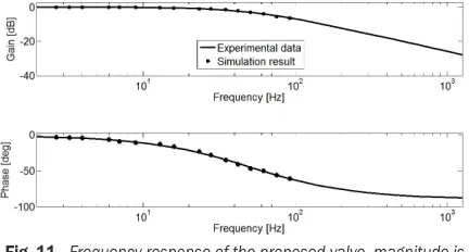
A sinusoidal input signal with amplitude voltage of 5 V and biased input voltage of 65 V was put to the valve at various frequencies. The frequency characteristics of the valve’s pressure response were analysed with a Bode diagram as shown in Fig. 11. The bandwidth for the proposed valve with isothermal load chamber is about 50 Hz.
Fig. 11. Frequency response of the proposed valve, magnitude is normalized by static gain
Studying existing pneumatic control system
having actuators with slow response (≈20 Hz) reveals
2 DESIGN OF THE CONTROLLER FOR THE PROPOSED VALVE
The governing equations of the designed valve are highly nonlinear and contain some parametric uncertainties. Use of nonlinear control criteria would give a far more precise control of the desired output flow rate or pressure. One of the well-known effective nonlinear robust control approaches is sliding mode control [17] and [18]. Primarily, a sliding mode controller was designed to control the output flow rate and pressure in the load chamber. The sliding mode control approach can be used to overcome the significant system nonlinearities initiated during pressure or flow rate control process in the presence of uncertainties. The proposed valve is considered as a single input-single output (SISO) nonlinear system, which can be easily described with the following state-space equation:
pb= f p1
( )
b − f p2( )
b − f p u3( )
b ⋅ , (10) where f1, f2 and f3 are nonlinear mass flow rate functions through the input, output, and variable orifices, respectively. They are also results of product (Rθa/V) in mass flow rate Eq. (7), for the orificescorresponding to fi where i = 1, 2 and 3. Variable u
is the control input denoted as the distance between nozzle head and flapper Xn.
The main variables that contain uncertainties are volume of the control chamber V and its temperature
θa. The overestimated variation of the load chamber’s
volume is about ±5 %. Temperature fluctuation is about ±2 K. The upper and lower bounds of the functions fi are given by:
f R
V G i
i a
i i
max
max
. , ,
= θ ⋅ =
0 95 ; 1 2 3, (11)
f R
V G i
i a
i i
min
min
. , , .
= θ ⋅ =
1 05 ; 1 2 3 (12)
The control objective is designed to guarantee the state of pb to track a desired state of pbd in the
presence of uncertainties. The relevant tracking error is introduced as follows:
e p= b−pbd. (13)
Furthermore, the sliding surface is described by [18]:
S e t d
dt e dt
n
, ,
( )
= + ∫ ⋅
−
λ
1
(14)
where n is system order and λ is a strictly positive constant that can be interpreted as the slope of the sliding surface in the phase plane. It can be seen that the integral of system error in the sliding surface (Eq. (14)) minimizes the reaching time. It is easy to show that this integral term will also increase the system order by one. Therefore, the system order for the proposed valve as pressure control is two. The sliding surface equation where n = 2 is given by:
S e t d
dt e dt e e dt
, ,
( )
= +
∫ ⋅ = + ∫ ⋅
−
λ λ
2 1
(15)
time derivatives of the above equation lead to a linear error equation:
S e t
( )
, = +e λe, (16) rearranging above equations:
S e t
( )
, = pb−pbd+λe, (17) using Eq. (17) and Eq. (10), results in:
S e t
( )
, = f p1( )
b − f p2( )
b − f p u p3( )
b − bd+λe, (18) satisfying the sliding condition:1 2
2
⋅d <
dtS ηS, (19)
η is a positive constant, guaranteeing that the surface S will nonetheless be reached in a finite time smaller than S(t = 0) / η; see [18] for more details. The sliding mode control law is also well presented by:
u u= eq+us, (20)
where ueq is the equivalent control signal that keeps
the state within sliding surface and us is the switch
function that compensates the state when leaving the sliding surface. The best estimation for ueq is obtained
by setting S=0 then from Eq. (18) ueq is derived:
f p1
( )
b − f p2( )
b − f p u p3( )
b − bd+λe=0, (21)where f1 and f2 are unknown functions that are presented by upper and lower bounds and are easily estimated by f1 and f2 which present the mean value
of upper and lower bounds so:
ueq= f
(
f − f −pbd+ e)
−
31
1 2 λ . (22)
Error estimation of ( f1 – f2) is considered to be bounded by function F(e, t):
F e t
( )
, ≥(
f1−f2)
−(
f1− f2)
. (23)f f f
3= 3max⋅ 3min, (24) taking a simple form for switching control input:
us = − ⋅K Sat S
ϕ , (25)
φ is a strictly positive constant that is explained as a boundary layer thickness neighbouring the sliding surface which prevents chattering and Sat (s/φ) is:
Sat S
S S
Sign S S
ϕ
ϕ ϕ
ϕ ϕ
=
<
≥
; if
; if
. (26)
To fulfil essential conditions for Eq. (19) K has to be defined large enough [18]:
K=β
(
F+η)
+(
β−1)
ueq, (27)where β = ( f3max / f3min )0.5 is defined as gain margin.
The control law which ensures existence of sliding motion in the state – space, provided that f3≠ 0 is:
u f= ueq− ⋅K sat S
−
3 1
ϕ . (28)
The specified tuning constants of λ and η are set so that the tracking error approaches zero with guaranteed stability. In this case, using trial and error experiments for realizing stability condition in Eq. (19) these constants were suitably adjusted to be 3500 s–1 and 550 kg·(m·s3)–1, respectively.
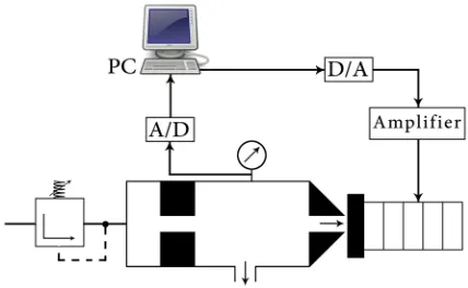
As previously mentioned, the proposed control approach in this part is implemented through a MATLAB/SIMULINK environment. The generated control signals using MATLAB/ Real-time workshop environment with the data acquisition board are used to drive the piezoelectric actuator through the power amplifier. The block diagram of this system is shown in Fig. 12, which clearly indicates that the desired flow rate Qd is converted to the desired pressure pbd,
through reverse function f2–1 which is a simple result from Eq. (7). This is an indication that the desired flow rate is derived simply by controlling the pressure of the load chamber. Any time the operators want to run the control program, they should simply introduce one of the reference inputs, either the pressure or flow rate separately, and set the other input to zero. Through first box in Fig. 12 the desired pressure is initiated and determined, then the controller based on this data and, from the pressure sensor installed on the load chamber, generates appropriate control input to
decrease the error between the desired and measured pressure.
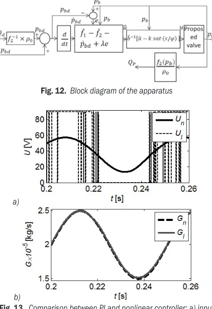
Fig. 12. Block diagram of the apparatus
a)
b)
Fig. 13. Comparison between PI and nonlinear controller; a) input voltage b) mass flow rate
The first controller that is selected to control a process is a linear controller, such as a PI-controller. To illustrate the effectiveness of the selected nonlinear controller, a set of simulations using a PI-controller were performed and compared with simulation results of the sliding mode approach that was selected to control the proposed valve. A computer program was arranged, both controllers were tuned, and their optimum control coefficients were calculated. Fig. 13 shows simulation results of the proposed valve with a PI- controller and the valve with sliding mode controller. The desired output flow rate was set at [2+0.5sin(ωt)]×10–5 kg/s at the frequency of 20 Hz. Part (a) of the figure shows the input voltage to the piezoelectric actuator with PI-controller Ul and nonlinear controller Un. Part (b) of
the figure shows simulation results using a sliding mode approach Gn and simulation results using a
PI-controller Gl. The performance of the nonlinear
the linear controller. Also, there is no phase delay in either controller. Part (a) of the figure illustrates that actuating frequency of the piezoelectric actuator with a nonlinear controller is similar to the frequency of the desired flow rate, but the actuating frequency of the actuator with a linear controller is much bigger than the frequency of the same desired flow rate. Furthermore, the nonlinear controller does not need a full range of actuation which is the case for the linear one. Since high actuating frequencies in the full range of motion could be harmful to piezoelectric material and decreases its life expectancy, it is much better to use a sliding mode approach to control output the flow rate or pressure of the valve.
3 RESULTS AND DISCUSSIONS
3.1 Generation of Steady Flow and Pressure
Steady flow or pressure of the proposed valve was generated separately. To evaluate the steady pressure generation ability of the proposed valve, output orifice in Fig. 1 was closed. Results are shown in Fig. 14, where the target pressures are set at 350 kPa and 450 kPa, respectively. The figure shows the reference pressure pbr and the actual pressure of the closed load
chamber pb. The results illustrate effective pressure
control of the load chamber so that error between the desired pressure pbr and the actual pressure pb is less
than 1.5 % at any set pressure.
Fig. 14. Steady pressure generation within the closed load chamber
To evaluate the proposed valve’s steady flow production ability through the output orifice, similar to above-mentioned method, some desired flow was introduced as reference flow to the computer of the controller; the generated flow through the output orifice was then measured by a QFS a quick response laminar flow sensor. Fig. 15 shows the results when the reference flow was set at 0.6×10⁻⁵ m3/s and 1.1×10⁻⁵ m3/s. Fig. 15 shows the reference flow Qr and the measured generated flow Qp resulted from the
pressure change using Eq. (5). The difference between the reference flow Qr and the generated flow Qp is less
than 2.5 %.
The results of steady pressure and flow generation, demonstrate that the proposed valve can deliver the desired steady flow from output orifice or produce a reference pressure conditions in a closed chamber with acceptable accuracy.
Fig. 15. Steady flow rate delivery
3.2 Generation of Unsteady flow and Pressure
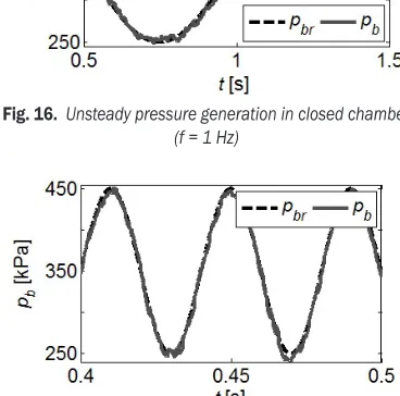
The experimental results from the oscillatory pressure condition in the closed load chamber of the valve at two different frequencies of 1 Hz and 25 Hz are presented in Figs. 16 and 17, respectively. The desired pressure was set at the sinusoidal pressure of [3.5+sin(ωt)]×105 Pa. The figures show the reference
Fig. 16. Unsteady pressure generation in closed chamber (f = 1 Hz)
pressure pbr and the actual pressure of the closed load
chamber pb. There is a small difference between pbr
and pb at the top and bottom of the sinusoidal curves.
Since the pressure change becomes smaller in these areas, the effect of the noise of the pressure sensor becomes larger, but pbr and pb show acceptable limits,
as the maximum error between pbr and pb is less than
2.5 %. In particular, the phase has no delay.
The experimental results for oscillatory flow rate are shown in Figs. 18 and 19, similar to Figs. 16 and 17 for pressure results. The desired output flow rate was set at [0.75+0.45sin(ωt)]×10–5 m3/s at different frequencies of 1 Hz and 25 Hz, respectively. The following figures show the desired flow Qr and the
produced output flow Q˝p, which was derived from pressure sensor data based on Eq. (5). The effect of the noise of the pressure sensor was increased and therefore small differences between Qr and Qp are
detectable. Hence, the flow Qp obtained from the
pressure using Eq. (5) is affected by the noise, Qr
and Qp are within acceptable limits. In particular,
there is no phase delay. The flow Qp is calculated
from the measured pressure based on Eq. (5) and is estimated within an uncertainty of 3.5 %. Therefore, the experimental results indicate that the proposed valve can produce oscillatory flow within the same accuracy. Results obtained for Qr and Qp at a wide
range of frequencies from 1 Hz to 25 Hz, represent excellent agreement for the developed valve model and the experimental data.
Fig. 18. Unsteady flow rate delivery (f = 1 Hz)
Fig. 19. Unsteady flow rate delivery (f = 25 Hz)
4 CONCLUSION
A new piezo-actuated NF valve with isothermal load chamber is introduced. This valve can control pressure or output flow rate separately using only a single pressure sensor. The valve could also be used as a pilot stage of a multistage valve. The effectiveness of the proposed valve has been confirmed and validated experimentally both for steady and unsteady conditions, where it can be operated as a pressure control valve or flow rate generator. The error is less than 2 %, in creating steady and unsteady pressure conditions. As a flow control valve, the designed valve setup can generate steady or sinusoidal oscillatory flow up to 25 Hz within an uncertainty of 3.5 %. Accurate controlling of pressure or flow rate of the valve with nonlinear dynamic behaviour with uncertainty is possible by using the sliding mode control method. It was proved that nonlinear controller is better than a linear one for this valve.
5 NOMENCLATURE
a flow rate gain with respect to load chamber pressure [kg·(s·Pa)–1]
b critical pressure ratio [–]
e tracking error of the load chamber pressure [kPa] C sonic conductance [m3·(s·Pa)–1]
Doi diameter of the input orifice [mm]
Doo diameter of the output orifice [mm]
G mass flow rate [kg·s–1] n order of the control system [–] pb control chamber pressure [kPa]
ps supply pressure [kPa]
Q volumetric flow rate [m3·s–1] R gas constant [J·(kg·K)–1] Se orifice effective area [mm2]
Tc time constant of the pressure response [s]
Kc proportional gain of the pressure response
[Pa·V–1]
v piezoelectric actuating voltage [V] V control chamber volume [m3] W air mass in chamber [kg]
Xn gap between flapper and head of nozzle [mm]
ϴb temperature in control chamber [K]
β gain margin [–]
ρ air density [kg·m–3]
λ slope of sliding surface [s–1]
6 REFERENCES
[1] Herakovic, N., Noe, D. (2006). Analysis of the operation of pilot-stage piezo-actuator valves. Strojniški vestnik - Journal of Mechanical Engineering, vol. 52, no. 12, p. 835-851. [2] Huang, W., Zhao, Z., Zhao, Y., Qi, Q., Huang, Q. (2008). Dynamic
characteristic research for piezo pneumatic intelligent valve positioner. 3rd IEEE Conference on Industrial Electronics and
Applications, p. 665–669, DOI:10.1109/ICIEA.2008.4582598. [3] Zeng, H., Yuan, R.-B., Sun, C., Zhang, Z. (2012).Study
on performance of laminated piezoelectric pneumatic servo valve. Procedia Engineering, vol. 31, p. 1140-1148, DOI:10.1016/j.proeng.2012.01.1154.
[4] Richer, E., Hurmuzlu, Y. (2000). A high performance pneumatic force actuator system: Part I—nonlinear mathematical model. Journal of Dynamic Systems, Measurement, and Control, vol. 122, no. 3, p. 416-425, DOI:10.1115/1.1286336.
[5] Wang, T., Cai, M., Kawashima, K., Kagawa, T. (2005). Modelling of a nozzle-flapper type pneumatic servo valve including the influence of flow force. International Journal of Fluid Power, vol. 6, no. 3, p. 33-43, DOI:10.1080/14399776.2005.107812 28.
[6] Kawashima, K., Youn, C., Toshiharu, K. (2006). Development of a nozzle-flapper-type servo valve using a slit structure. Journal of Fluids Engineering, vol. 129, no. 5, p. 573-578, DOI:10.1115/1.2717617.
[7] Peng, Z., Sun, C., Yuan, R., Zhang, P. (2012). The CFD analysis of main valve flow field and structural optimization for double-nozzle flapper servo valve. Procedia Engineering, vol. 31, p. 115-121, DOI:10.1016/j.proeng.2012.01.1000.
[8] Aung, N.Z., Li, S. (2014). A numerical study of cavitation phenomenon in a flapper-nozzle pilot stage of an electrohydraulic servo-valve with an innovative flapper shape. Energy Conversion and Management, vol. 77, p. 31-39, DOI:10.1016/j.enconman.2013.09.009.
[9] Kagawa, T. (1985). Heat transfer effects on the frequency response of a pneumatic nozzle flapper. Journal of Dynamic
Systems, Measurement, and Control, vol. 107, no. 4, p. 332-336, DOI:10.1115/1.3140744.
[10] Kawashima, K., Kagawa, T. (2003). Unsteady flow generator for gases using an isothermal chamber. Measurement, vol. 33, no. 4, p. 333-340, DOI:10.1016/S0263-2241(03)00003-4. [11] Kawashima, K., Fujita, T., Kagawa, T. (1997) Unsteady flow rate
measurement of air using isothermal chamber. Transaction of The Society of Instrument and Control Engineers, vol. 33, no. 3, 149–154, DOI:10.9746/sicetr1965.33.149.
[12] Kawashima, K., Ishii, Y., Funaki, T., Kagawa, T. (2004). Determination of flow rate characteristics of pneumatic solenoid valves using an isothermal chamber. Journal of Fluids Engineering, vol. 126, no. 2, p. 273-279, DOI:10.1115/1.1667888.
[13] Wang, T., Kawashima, K., Kagawa, T. (2007).Determination of characteristics for electrically modulated pneumatic control valves using isothermal chambers. International Journal of Fluid Power, vol. 8, no. 3, p. 5-11, DOI:10.1080/14399776.2 007.10781281.
[14] Zhao, Y., Jones, B. (1991). A power air-jet actuator with piezotranslator drive stage. Mechatronics, vol. 1, no. 2, p. 231-243, DOI:10.1016/0957-4158(91)90045-C.
[15] PI Piezo Nano Positioning Catalog (2014/2015). from http:// www.physikinstrumente.com/info/catalogs-brochures-certificates.html, accessed at 2015-12-26.
[16] ISO6358-1:2013 (2013). Pneumatic fluid power--Determination of flow-rate characteristics of components using compressible fluids -- Part 1: General rules and test methods for steady-state flow. International Organization for Standardization, Geneva.
[17] Slotine, J.-J.E., Li, W. (1991). Applied Nonlinear Control. Prentice-Hall Englewood Cliffs.