Volume 4, Issue 4, 2017
Available online at www.ijiere.com
International Journal of Innovative and Emerging
Research in Engineering
e-ISSN: 2394 - 3343 p-ISSN: 2394 - 5494
Harmonic Minimization Using Shunt Active Filter by
Using Different Controllers
Prof. Jivan Patil
1, Prof. Sharad Bhosale
2Prof. Chinala Mallareddy
3Assistant Professor, FTC-COER, Sangola, Solapur affilated to Solapur University Solapur, Maharashtra, India Assistant Professor, FTC-COER, Sangola, Solapur affilated to Solapur University Solapur, Maharashtra, India Head of Electrical Engineering Department, FTC-COER, Sangola, Solapur affilated to Solapur University Solapur,
Maharashtra, India
ABSTRACT:
In our day-to-day life, every load creates harmonics and due to the nonlinear load there is serious problem of harmonic with system. Due to the harmonics, there is distortion in voltage and current waveform. In addition, computers, battery chargers, electronic ballasts, variable frequency drives and switched mode power supply generate large amount of harmonics. Issues related to harmonics is a major thing nowadays because they can overheat the building wiring, causes nuisance tripping, overheat transformer units, and cause random end-user equipment failures. Thus there is serious problem with power quality. To avoid this thing, use shunt active power filters (SAPFs), due to their excellent harmonic compensation.
The main objective of this paper is to analyse the result of shunt active filters with controllers. To carry out this analysis active and reactive power (P-Q) and instantaneous active and reactive current (Id-Iq) control strategies are
considered. A simulation is to be carried out with different controllers for both active and reactive power (P-Q) and instantaneous active and reactive current (Id-Iq) control strategies under different voltage conditions. Using
instantaneous active and reactive current (Id-Iq) control method with fuzzy logic controller gives an outstanding
performance under any voltage conditions as compared to PI controller.
Keywords: Harmonic Compensation, Shunt Active Filter (SHAF), and p-q Control Strategy, id-iq Control Strategy,
PI Controller and Fuzzy Controller.
INTRODUCTION
In recent years power quality has become an important and growing problem due to the proliferation of nonlinear loads such as power electronic converters in typical power distribution systems [1]. Particularly, voltage harmonics and power distribution equipment problems are the result of current harmonics [2] produced by nonlinear loads.
Eminent issues always arise in three-phase four-wire systems. It is well-known that zero line may be overheated or causes a fire as a result of excessive harmonic current going through the zero line three times or times that of three. Thus a perfect compensator is necessary to avoid the negative consequences of harmonics. Though several control techniques and strategies have been developed they still have contradictions with the performance of filters.
A shunt active power filter (SAPF) generates a harmonic current spectrum that is opposite in phase to the harmonic and / or reactive current it perceives at the load end. Harmonic and reactive currents are thus cancelled at the source end and the result is undistorted sinusoidal balanced currents. The Active filters overcome the problems occurring in the passive filter. Major Advantage of Active Filter over Passive Filter is that it can be controlled to compensate for harmonics in such a way that Total Harmonic Distortion (THD) lower than 5% at the Point of Common Coupling can effectively be achieved. The shunt active filter can also be made to act as a damping device in a parallel resonance circuit formed by the passive filter and the power supply system by adopting a lead function in its controller. Thus it can prevent harmonic propagation resulting from harmonic resonances.
SHUNT ACTIVE POWER FILTER A. INTRODUCTION
The remedies for power-quality (PQ) problems are available in two forms: 1) Passive filters and active filters for existing systems and
2) Establishing new improved PQ converters
Volume 4, Issue 4, 2017 each offering their own unique solution to reduce and eliminate harmonics. These harmonic filters are broadly classified into passive, active and hybrid structures. The choice of filter used is dependent upon the nature of the problem and the economic cost associated with implementation.
A passive filter is composed of only passive elements such as inductors, capacitors and resistors thus not requiring any operational amplifiers. Passive filters are inexpensive compared with most other mitigating devices. Its structure may be either of the series or parallel type. The structure chosen for implementation depends on the type of harmonic source present. Internally, they cause the harmonic current to, through this approach; the harmonic currents are attenuated in the LC circuits tuned to the harmonic orders requiring filtering. This prevents the severe harmonic currents travelling upstream to the power source causing increased widespread problems.
An active filter is implemented when orders of harmonic currents are varying. One case evident of demanding varying harmonics from the power system are variable speed drives. Its structure may be either of the series of parallel type. The structure chosen for implementation depends on the type of harmonic sources present in the power system and the effects that different filter solutions would cause to the overall system performance. Active filters use active components such as IGBT-transistors to inject negative harmonics into the network effectively replacing a portion of the distorted current wave coming from the load. This is achieved by producing harmonic components of equal amplitude but opposite phase shift, which cancel the harmonic components of the non-linear loads. Hybrid filters combine an active filter and a passive filter. Its structure may be either of the series or parallel type. The passive filter carries out basic filtering (for example 5th order) and the active filter, through precise control, covers higher harmonics.
B. ROLES OF FILTERS IN POWER SYSTEM The types of filters are
The Passive Filters
The Active Filters
The Hybrid Filters
Capacitors are frequently used in the Active and Passive filters for harmonics reduction.The Passive filters are used in order to protect the power system by restricting the harmonic current to enter the power system by providing a low impedance path. Passive filters consist of resistors, inductors and capacitors. The Active filters are mostly used in distribution networks for sagging in voltage, flickering, where there are harmonics in current and voltages, etc. Using the filter would result into a better quality of power. There is also a third type of filter which is used i.e. The Hybrid Filter . Hybrid filters are composed of the passive and active filters both.
C. PASSIVE FILTERS
Passive filters are a simple concept, but can be more complicated in reality. The design of passive filters is quite involved and is covered in some detail in texts dealing specifically with harmonics. Two types of passive filters are band pass, for specific harmonics, and high pass, for a range of harmonics. The use of the passive filter is a simple, reliable, and cost-effective alternative but its performance is dependent of the load. A Passive filter consists of a Series/Parallel combination of an inductor, a capacitor and a resistor specially tuned to filter a particular frequency current. The impedance of L-C tuned filter is lower than the source impedance at a particular harmonic frequency in order to absorb that harmonic current Passive filter have an advantage of low cost, are less complicated and have high efficiency.
However, they suffer from a serious limitation that their performance gets affected significantly due to the variation in the filter component values, filter component tolerance, source impedance, and frequency of ac source. Also, they may cause series and load resonances in the system. In this scenario, harmonic currents can get amplified on the source side and cause serious distortion in the voltage .The passive filters also tend to get overloaded in case the load harmonics increase. As in stiff utility system poses greater difficulty for design of passive filter because sharp tuning and high quality factor are required to sink harmonic current.
The simplest method of eliminating line current harmonics and improving the system power factor is to use passive LC filters. However, the main drawbacks of passive LC filters are
a) Bulk passive components b) series and parallel resonance c) fixed compensation characteristic
D. ACTIVE FILTER
i) Introduction to Shunt Active Power Filter
Volume 4, Issue 4, 2017 resonance circuit formed by the passive filter and the power supply system by adopting a lead function in its controller .Thus it can prevent harmonic propagation resulting from harmonic resonances.
Advantages of Active Filter over Passive Filter:
One of the main advantage of active filter over the passive filter is that it can be used to reduce the effects of harmonics of more than one order.
Active filters are also useful in flickering problems that are caused in the power system.
For the conditions where both voltage and current are leading to a deterioration in power system, more complex filters are used which are made up of combination of active and passive filters. Such filters are called as Hybrid Filters.
In a modern power system, increasing of loads and nonlinear equipment’s have been demanding the compensation of the disturbances caused for them. These non-linear loads may cause poor power factor and high degree of harmonics. Active power filter (APF) can solve problems of harmonic and reactive power simultaneously. APF’s consisting of voltage source inverters and a dc capacitor have been researched and developed for improving the power factor and stability of transmission systems.
APF have the ability to adjust the amplitude of the synthesized ac voltage of the inverters by means of pulse width modulation or by control of the dc-link voltage, thus drawing either leading or lagging reactive power from the supply. APF’s are an up-to-date solution to power quality problems. Shunt APF’s allow the compensation of current harmonics and unbalance, together with power factor correction and can be a much better solution than conventional approach (capacitors and passive filters).
In APF design and control, instantaneous reactive power theory was often served as the basis for the calculation of compensation current. In this theory, the mains voltage was assumed to be an ideal source in the calculation process. However, in most of time and most of industry power systems, mains voltage may be unbalanced and/or distorted. Under such scenarios, this theory may not be valid for application
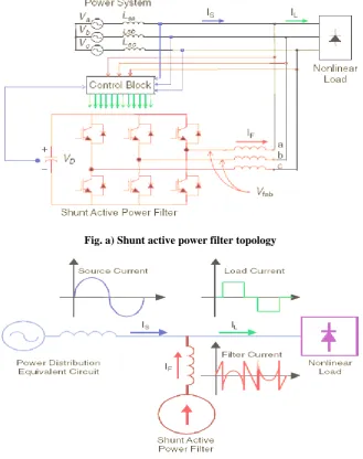
Fig. a) Shunt active power filter topology
Fig. b) Filter current IF generated to compensate load-current harmonics
Volume 4, Issue 4, 2017 topology similar to that of a static compensator (STATCOM) used for reactive power compensation in power transmission systems. Shunt active power filters compensate load current harmonics by injecting equal-but opposite harmonic compensating current. In this case the shunt active power filter operates as a current source injecting the harmonic components generated by the load but phase-shifted by 180°.
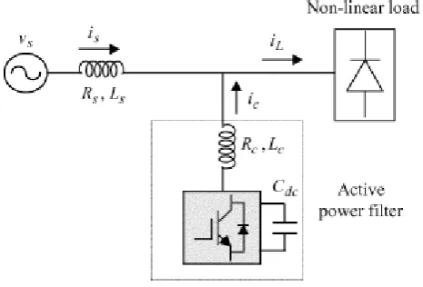
ii) Basic Compensation Principle
Fig. c) shows the basic compensation principle of a shunt active power filter. It is controlled to draw / supply a compensating current ic from / to the utility, so that it cancels current harmonics on the AC side, and makes the source current in phase with the source voltage. Fig. d). shows the different waveforms in this Curve A is the load current waveform and curve B is the desired mains current. Curve C shows the compensating current injected by the active filter containing all the harmonics, to make mains current sinusoidal.
Fig c) Shunt active power filter Basic compensation principle
Fig. d) Shunt active power filter-shapes of load, source and desired filter current waveforms
iii) Shunt Active Power Filter Operation:
In ideal conditions, the source current must be sinusoidal, harmonic less. In order to ensure this, Shunt APF is employed to compensate current harmonics in supply. Shunt APF supplies compensating current in phase opposition to all harmonics present in supply current. Shunt Active Power Filters are mainly operated as harmonic isolator between nonlinear load and utility system. The Shunt APF connected in parallel to supply system protects utility from harmonics generated by non-linear load. It can be used to provide reactive power to the load as well.
Shunt APF system can be divided into two sections as: The control unit and the power circuit. Control unit consists of reference signal generation, gate signal generation, capacitor voltage regulation and voltage/current measurement. Power circuit of APF is generally comprised of energy storage unit, DC/AC converter, harmonic filter and system protection.
Volume 4, Issue 4, 2017 or the one which are working in both. Time domain methods, such as p-q or d-q based methods are discussed and allow the fast compensation of time-variant disturbances but make more complex their selective compensation. In this sense, frequency domain methods are more flexible but their dynamical response is slower. A new control strategy is proposed, which is proper compositions of d-q-0, and Fourier transform theories that is easy for complementation. This approach can control power flow as well as power quality compensation.
Designing a suitable controller for an APF is very important. A number of control strategies such as instantaneous reactive power theory initially developed by Akagi, synchronous frame d–q theory, synchronous detection method, are used in the development of three-phase APFs and the gate pulses are generated by current control technique like sinusoidal pulse width modulation (SPWM), Space Vector PWM, hysteresis current control technique.
iv. Shunt Active Power Filter Application
The Active Power filters (APF) are a highly flexible solution to the problem of harmonic pollution in power networks. The Active Power filters (APF) are also called active power line conditioners (APLC), instantaneous reactive power compensators (IRPC) and active power quality conditioners (APQC). Currently Different approaches such as notch filter, (Newman et al., 2002), scalar control, (Chandra etal., 2000), instantaneous reactive power theory(IRP), ( Furuhashi et al., 1990, Akagi et al., 2007), synchronous detection method, (Chen et al., 1993), synchronous d–q frame method (SRF), (Mendalek et al., 2003), flux-based control, (Bhattacharya et al., 1996), and closed loop PI, (Bhattacharya et al., 1996), internal model control, (Marconi et al., 2007), and sliding mode control, ( Saetieo et al., 1995), can be used to improve the active filter performance. Also, the direct power control method has found application in active filters, (Chen & Joós, 2008). Specific harmonics can be cancelled out in the grid using the selective harmonic elimination method (Lascu et al., 2007). In all cases, the goal is to design a simple but robust control system for the filter. The newly applied method in Active filter is On-off controller, neural network controller, Fuzzy logic controller. The application of artificial intelligence is growing fast in the area of power sectors. The artificial neural network (ANN) is considered as a new tool to design control circuitry for power quality (PQ) devices. The first neural network model is designed by McCulloch and Pitts (1943). A new learning algorithm for linear neural networks (ADALINE) Widrow & Hoff (1960). In Adaline based control method is presented and it is compared against traditional PID controller based approach. With the use of this artificial neural network algorithm, the functionality of the shunt active filter is enhanced.
CONTROL STRATEGY FOR SHUNT ACTIVE POWER FILTER
Control strategies used for Shunt Active Power Filter (SAPF) are mainly 1 Active and Reactive Power (P-Q) control strategy
2 Instantaneous active and reactive current (Id-Iq) control strategy
1 ACTIVE AND REACTIVE POWER (P-Q) CONTROL STRATEGY
In 1983, Akagi have proposed the "The Generalized Theory of the Instantaneous Reactive Power in Three-Phase Circuits", also known as p-q theory [5]. It is based in instantaneous values in three-phase power systems with or without neutral wire, and is valid for steady-state or transitory operations, as well as for generic voltage and current waveforms. The p-q theory consists of an algebraic transformation (Clarke transformation) of the three-phase voltages and currents in the a-b-c coordinates to the α-β-0 coordinates, followed by the calculation of the p-q theory instantaneous power components:
[ iα iβ i0
] = 2 3 [ 1 − 1 2 − 1 2 0 √3 2 −√3 2 1 √2 1 √2 1 √2] · [ ia ib ic ]………..(1) [ vα vβ v0
] = 2 3 [ 1 − 1 2 −1 2 0 √3 2 − √3 2 1 √2 1 √2 1 √2 ] . [ va vb vc ]
P0 = V0.I0 Instantaneous zero sequence power……….. (2)
p = vαiα + vβiβ Instantaneous real power
q = vαiα - vβiβ Instantaneous imaginary power
Volume 4, Issue 4, 2017 [p𝑞] = 3
2[
vα vβ −vβ vα] [
iα
𝑖𝛽]………..………. (3)
By taking the inverse of above matrix we get the value of iα and iβ
[
𝑖
i
α𝛽
]
=
23
∗
1 vα2+vβ2
[
v
α−v
βv
βv
α] [
p
𝑞]
………..……….. (4)
In the above matrix, we substitute
𝑝 = 𝑝𝑐= 0 𝑎𝑛𝑑 𝑞 = 𝑞𝑐= −𝑞
because compensator is supplying reactive power but it is not drawing any kind of active power. Therefore we get compensated current as,
[iαc𝑖 𝛽𝑐] =
2 3∗
1 vα2+vβ2[
vα −vβ vβ vα ] [
0
−𝑞]……….. (5)
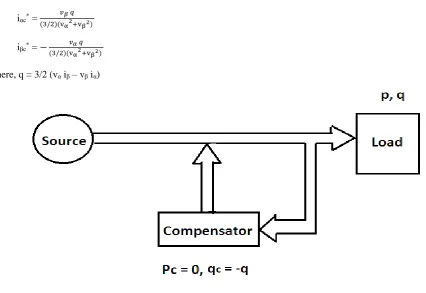
Reference compensated current with the help of fig. a) and is given by
iαc* = 𝑣𝛽 𝑞 (3/2)(vα2+vβ2)
iβc* = − 𝑣𝛼 𝑞 (3/2)(vα2+vβ2)
Where, q = 3/2 (vα iβ – vβ iα)
Fig. a) – Basic block diagram of the p-q theory using compensator
These quantities, illustrated in Fig. b) for an electrical system represented in α-β-0 coordinates, have the following physical meaning:
p0 = mean value of the instantaneous zero-sequence power corresponds to the energy per time unity which is transferred from the power supply to the load through the zero-sequence components of voltage and current.
p0
̃= alternated value of the instantaneous zero-sequence power it means the energy per time unity that is exchanged between the power supply and the load through the zero-sequence components. The zero-sequence power only exists
in three-phase systems with neutral wire. Furthermore, the systems must have unbalanced voltages and currents, or multiple of 3 harmonics in both voltage and current of at least one phase.
p = mean value of the instantaneous real power – corresponds to the energy per time unity which is transferred from the power supply to the load.
Volume 4, Issue 4, 2017 This component does not imply any transference or exchange of energy between the power supply and the load, but is responsible for the existence of undesirable currents, which circulate between the system phases. In the case of a balanced sinusoidal voltage system and a balanced load, with or without harmonics, q (the mean value of the instantaneous imaginary power) is equal to the conventional reactive power (q= 3.V. I1.sinφ1).
.
Fig. b) Powers components of the p-q theory in α-β-0 coordinates
i) The P-Q theory applied to Active Filters
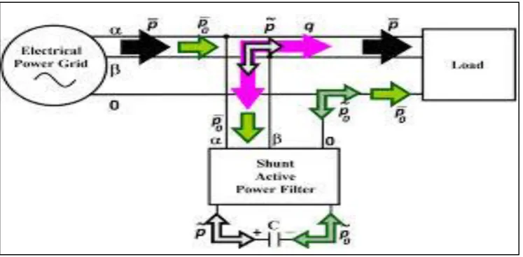
From all the power components obtained through the p-q theory, only p and p0 are desirable, as they correspond to the energy transferred from the supply to the load. The other quantities can be compensated using a shunt active power filter (Fig. c). even p0, which is related to a load unbalance (an undesirable operation condition), should be compensated whenever possible. Watanabe et al. presented a way to compensate p0, without the need of using any power supply in the active filter. They showed that the value of p0 can be delivered from the power source to the active filter through the α-β coordinates, and then the active filter can supply this power to the load through the 0
coordinate as shown in Fig. c). This means that the energy previously transferred from the source to the load through the zero-sequence components of voltage and current, is now delivered from the source phases through the active filter, in a balanced way.
Fig. c) shows that the active filter capacitor is only necessary to compensate p ̃and p̃0, since these quantities must be stored in this component at one moment to be later delivered to the load. The instantaneous imaginary power (q), which includes the conventional reactive power, can be compensated without any capacitor.
Fig. c) Compensation of power components 𝒑̃, q, 𝒑̃𝟎 and 𝒑̅̅̅ in α-β-0 Co-ordinates 𝟎
If the undesired power components (q,p̃, p0̅̅̅ ,p0̃ , 0 ) are compensated, and for a three-phase system with balanced sinusoidal voltages, the supply currents are also sinusoidal balanced, and in phase with the voltages. In other words, the power supply “sees” the load as a purely resistive symmetrical load. Since all the instantaneous zero -sequence power will be compensated, the reference compensation current in the 0 coordinate is i0 itself: ic0∗= i0. To calculate the reference compensation currents in the α-β coordinates, the expression (3) is inverted and the powers to be compensated (p and q) are used:
Volume 4, Issue 4, 2017 2. Excellent steady-state performance with ideal supply voltage.
Disadvantages of Active and Reactive Power (P-Q) Theory: 1. Large number of voltage and current transducers are required
2. This method is poor in compensation of harmonic current if source voltages are not symmetrical.
3. Performance is poor if an APF is also required to compensate the negative and zero sequence current in the load having delay in compensation
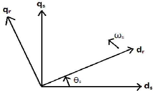
2 INSTANTANEOUS ACTIVE AND REACTIVE CURRENT (Id-Iq) CONTROL STRATEGY
Fig d) Vector representation of synchronously rotating frame
Notations s Stationary
r Rotating
dθs
dt = ωs
[ds qs] = [
cosθs −sinθs sinθs cosθs ] [
dr
qr]………... (6)
[𝑑𝑟 qr] = [
cos𝜃𝑠 sin𝜃𝑠 −sin𝜃𝑠 cos𝜃𝑠] [
𝑑𝑠
qs]………... (7)
Fig e) Relation between stationary and rotating reference frame
In the above matrix, ds, qs, dr, qr it may be voltage, current or flux as per our requirement or application. In above fig e), we use positive x-axis and positive y-axis for d-q transformation, but we can take negative also. In the above
figure vector rotator is nothing but this matrix[−sin𝜃cos𝜃𝑠 sin𝜃𝑠 𝑠 cos𝜃𝑠].
Volume 4, Issue 4, 2017 same. If the voltage non- sinusoidal we get pulsating waveform and frequency information is required. To avoid this and get sinusoidal waveform we use filter. Here we use DC filter because there is phase shift problem in AC filter.
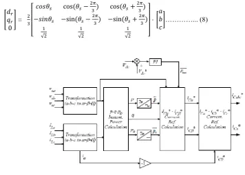
[ 𝑑𝑟 𝑞𝑟 0
] = 2 3
[
𝑐𝑜𝑠𝜃𝑠 cos (𝜃𝑠− 2𝜋
3) cos (𝜃𝑠+ 2𝜋
3) −𝑠𝑖𝑛𝜃𝑠 −sin(𝜃𝑠−2𝜋
3) −sin(𝜃𝑠+ 2𝜋
3) 1
√2
1 √2
1
√2 ]
· [ 𝑎 𝑏 𝑐
]…………... (8)
Fig f) Reference current extraction with id-iq method
In Figure f), the entire reference current generation scheme has been illustrated. The load currents iLa, iLb and
iLc are tracked upon which Park’s transformation is performed to obtain corresponding d-qaxes component as given
in (6) and (7), where ω is rotational speed of synchronously rotating d-qframe. According to id-iq control strategy, only the average value of d-axis component of load current should be drawn from supply. Here iLd1h and iLq1h indicate
the fundamental frequency component of iLd and iLq. The oscillating components iLd and iLq, i.e., iLdnh and iLqnh are filtered out using low-pass filter.
The reference signals thus obtained are compared with the actual compensating filter currents in a hysteresis comparator, where the actual current is forced to follow the reference and provides instantaneous compensation by the APF on account of its easy implementation and quick prevail over fast current transitions. This consequently provides switching signals to trigger the IGBTs inside the inverter. Ultimately, the filter provides necessary compensation for harmonics in the source current and reactive power unbalance in the system. Figure g) shows voltage and current vectors in stationary and rotating reference frames. The transformation angle ‘θ’ is sensible to all voltage harmonics and unbalanced voltages; as a result dθ/dt may not be constant.
One of the advantages of this method is that angle θ is calculated directly from main voltages and thus makes this method frequency independent by avoiding the PLL in the control circuit. Consequently synchronizing problems with unbalanced and distorted conditions of main voltages are also evaded. Thus id-iq achieves large frequency operating limit essentially by the cut-off frequency of voltage source inverter (VSI).
Fig. g) Instantaneous voltage and current vectors
Volume 4, Issue 4, 2017 P = 3
2 𝑣𝑠 𝑖𝑠 cosΦ = 3
2 𝑣𝑠𝑟 𝑖𝑑𝑟 ……….………... (9) q = 3
2 𝑣𝑠 𝑖𝑠 sinΦ = 3
2 𝑣𝑠𝑟 𝑖𝑞𝑟 ……….………... (10)
Figures f) and g) show the control diagram for shunt active filter and harmonic injection circuit. On owing load currents id and iq are obtained from park transformation then they are allowed to pass through the high pass filter to eliminate dc components in the nonlinear load currents. Filters used in the circuit are Butterworth type and to reduce the influence of high pass filter an alternative high pass filter (AHPF) can be used in the circuit. It can be obtained through the low pass filter (LPF) of same order and cut-off frequency simply difference between the input signal and the filtered one, which is clearly shown in Figures 4.3. Butterworth filters used in harmonic injecting circuit have cut-off frequency equal to one half of the main frequency (fc = f /2), with this a small phase shift in harmonics and sufficiently high transient response can be obtained.
Advantage of Active and Reactive Current (Id-Iq) Theory:
This method is best suitable for harmonic compensation with sinusoidal source voltage. Disadvantage of Active and Reactive Current (Id-Iq) Theory:
Large number of voltage and current transducers are required having delay in compensation.
CONTROLLERS
The following controllers are used in this project to control the various parameters and system response. 1) PI Controller
2) Fuzzy Logic Controller (FLC)
1) PI CONTROLLER
Proportional + Integral (PI) controllers were developed because of the desirable property that systems with open loop transfer functions of type 1 (fig a) or above have zero steady state error with respect to a step input.
The PI regulator is given by:
U(S) / E(S) = Kp+ (KI/ S) ……….………... (12)
Fig. a) PI Controller with type 1 system
Volume 4, Issue 4, 2017 𝑈(𝑆)
𝐸(𝑆) = −(1
𝑆𝐶)+ 𝑅2
𝑅1 ……….…………... (13)
PI controller (fig b) will eliminate forced oscillations and steady state error resulting in operation of on-off controller and P controller respectively. However, introducing integral mode has a negative effect on speed of the response and overall stability of the system. Thus, PI controller will not increase the speed of response. It can be expected since PI controller does not have means to predict what will happen with the error in near future. This problem can be solved by introducing derivative mode which has ability to predict what will happen with the error in near future and thus to decrease a reaction time of the controller.
PI controllers are very often used in industry, especially when speed of the response is not an issue. A control without D mode is used when:
a) Fast response of the system is not required
b) Large disturbances and noise are present during operation of the process c) There is only one energy storage in process (capacitive or inductive) d) There are large transport delays in the system
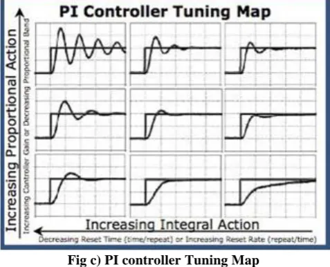
i) CHALLENGES OF PI CONTROLLER:
There are challenges in employing the PI algorithm:
1. The two tuning parameters interact with each other and their influence must be balanced by the designer. 2. The integral term tends to increase the oscillatory or rolling behavior of the process response.
Because the two tuning parameters interact with each other, it can be challenging to arrive at “best” tuning values. The value and importance of our design and tuning recipe increases as the controller becomes more complex.
Fig c) PI controller Tuning Map
Fig. d) shows the internal structure of the control circuit. The control scheme consists of a PI controller, a limiter, and a three phase sine wave generator for reference current and switching signal generation. The peak value of the reference currents is estimated by regulating the DC link voltage.
Volume 4, Issue 4, 2017 The actual capacitor voltage is compared with a set reference value. The error signal is then processed through a PI controller, which contributes to the zero steady error in tracking the reference current signal. The output of the PI controller is considered as the peak value of the supply current (Imax), which is composed of two components:
1. The fundamental active power component of the load current, and
2. The loss component of the APF to maintain the average capacitor voltage at a constant value. The peak value of the current (Imax) so obtained, is multiplied by the unit sine vector sine phase with the respective source voltages to obtain the reference compensating currents. These estimated reference currents (Isa*, Isb*, and Isc*) and the sensed actual currents ( Isa, Isb, and Isc ) are compared to a hysteresis band, which gives the error signal for the modulation technique. This error signal decides the operation of the converter switches. In this current control circuit configuration, the source / supply currents Isabc are made to follow the sinuso idal reference current Iabc, within a fixed hysteretic band. The width of the hysteresis window determines the source current pattern, its harmonic spectrum and the switching frequency of the devices. [7]
The DC link capacitor voltage is kept constant throughout the operating range of the converter. In this scheme, each phase of the converter is controlled independently. To increase the current of a particular phase, the lower switch of the converter associated with that particular phase is turned on. To decrease the current the upper switch of the respective converter phase is turned on. With this the potential and the feasibility of the PI controller can be realized.
2) FUZZY LOGIC CONTROLLER (FLC)
Fuzzy logic is widely used in a machine control. The term "fuzzy" refers to the fact that the logic involved can deal with concepts that cannot be expressed as the "true" or "false" but rather as "partially true". Although alternative approaches such as genetic algorithms and neural networks can perform just as well as fuzzy logic in many cases, fuzzy logic has the advantage that the solution to the problem can be cast in terms that human operators can understand, so that their experience can be used in the design of the controller. This makes it easier to mecha nize tasks that are already successfully performed by humans. [8]
Fuzzy logic becomes more popular due to dealing with problems that have uncertainty, vagueness, parameter variation and especially where system model is complex or not accurately defined in mathematical terms for the designed control action. The conception of the fuzzy logic introduced by Zadeh is a combination of fuzzy set theory and fuzzy inference system (FIS). Elements of a fuzzy set belong to it with a certain degree, called degree of membership. The degree of membership is a result of mapping the input to certain rules using a membership function (MF). The progression which maps the specified input data to the output using fuzzy logic is known as fuzzy inference.
A fuzzy inference system can be classified as: a) Fuzzification
b) Inference engine c) Knowledge base d) Defuzzification
(a) Fuzzification:
Fuzzification is the process of converting any crisp value to analogous linguistic variable based on certain MF.
(b) Inference engine:
Inference engine simulates human decision.
(c) Knowledge base:
Knowledge base consists MF definitions and necessary rules like IF-THEN or it is combination of condition part with their associated rules.
(d) Defuzzification:
Defuzzification is the progression of transforming the fuzzy output into a crisp numerical value. For example, we take main control input variable is the DC-link voltage error and output of FLC is the peak value of the reference source current. The range of operating current, normalization and de-normalization is one of the important design factors of fuzzy controller.
A control system may also have various types of switch, or "ON-OFF", inputs along with its analog inputs, and such switch inputs of course will always have a truth value equal to either 1 or 0, but the scheme can deal with them as simplified fuzzy functions that happen to be either one value or another.
i) DESIGNING OF CONTROL RULES
Computational methods determine the computational efficiency, processor memory requirement and processing time. The fuzzy control rules based on membership function defining or relate input variables to output variables. The number and type of MF determines the computational efficiency of fuzzy control technique. The determination of MFs depends on the designer’s experience and knowledge. The shape decision of MFs affects how well a fuzzy system rules approximate a function.
Volume 4, Issue 4, 2017 input and output linguistic variables. The number of linguistic variables is directly related to the accuracy of approximating function and plays an important role for input-output mapping. However, some limits have to consider while designing number of linguistic variables in view of accuracy and complexity of FLC.
Fig. e) Detailed structure of fuzzy logic controller
A fuzzy controller converts a linguistic control strategy into an automatic control strategy, and fuzzy rules are constructed by expert experience or knowledge database. [10] Firstly, input voltage Vdc and the input reference voltage Vdc-ref have been placed of the angular velocity to be the input variables of the fuzzy logic controller. Then the output variable of the fuzzy logic controller is presented by the control Current Imax. To convert these numerical variables into linguistic variables, the following seven fuzzy levels or sets are chosen as:
a) NB (negative big), b) NM (negative medium), c) NS (negative small), d) ZE (zero),
e) PS (positive small), f) PM (positive medium), g) PB (positive big).
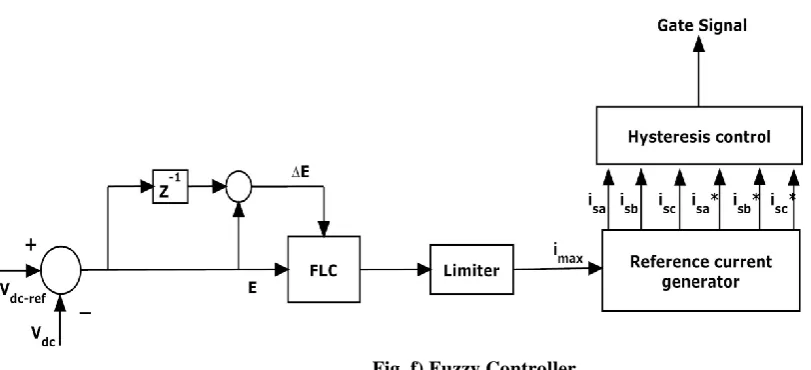
Volume 4, Issue 4, 2017 Figure f) shows the internal structure of the control circuit. The control scheme consists of Fuzzy controller, limiter, and three phase sine wave generator for reference current generation and generation of switching signals. The peak value of reference currents is estimated by regulating the DC link voltage. The actual capacitor voltage is compared with a set reference value. The error signal is then processed through a Fuzzy controller, which contributes to zero steady error in tracking the reference current signal.
The fuzzy controller is characterized as follows: 1) Seven fuzzy sets for each input and output;
2) Fuzzification using continuous universe of discourse; 3) Implication using Mamdani's ‘min’ operator;
4) Defuzzification using the ‘centroid’ method.
Fig. f) Fuzzy Controller
SIMULATION RESULTS:
The performance of Shunt Active Power Filter is studied for these Tree methods of control techniques, Under balanced / unbalance, steady / dynamic load condition, linear / nonlinear loads for both balanced as we ll as distorted source conditions and the following observations are made based on these results.
The Simulink model of the Shunt Active Power Filter is simulated in MATLAB/SIMULINK environment. The simulation results for different cases using Simulink block diagram are given below.
1. SHUNT ACTIVE POWER FILTER BY USING P-Q THEORY:
Volume 4, Issue 4, 2017
Fig. b) Simulation result of Source Current using P-Q Theory with Fuzzy Logic Controller
Fig. c) Simulation results of voltage across capacitor by using P-Q Theory with PI Controller
Fig. d) Simulation results of voltage across capacitor by using P-Q Theory with Fuzzy Logic Controller
2. SHUNT ACTIVE POWER FILTER BY USING Id-Iq THEORY WITH PI CONTROLLER
Volume 4, Issue 4, 2017
Fig. f) Simulation result of Source Current using Id-Iq Theory with Fuzzy Logic Controller
Fig. g) Simulation results of voltage across capacitor by using Id-Iq Theory with PI Controller
Fig. h) Simulation results of voltage across capacitor by using Id-Iq Theory with Fuzzy Logic Controller
Table: Comparison of PI and Fuzzy Logic Controller
Sr.
No. Parameter PI Controller Fuzzy Logic Controller
1 Transient Response Good Better
2 Undershoot and overshoot More Less
3 Steady State Response Good Better
4 % Error Less Slightly less than PI Controller
5 Load current Same Same
Volume 4, Issue 4, 2017 CONCLUSION
This paper presents an overview of Instantaneous Power and Current Strategies for Current Harmonics Cancellation using Shunt Active Power Filter with PI and fuzzy logic controllers. The controllers PI and fuzzy logic under balanced, unbalanced, non-sinusoidal control has to be validated for Shunt Active Power Filter (SAPF).Comparison of controllers with PI and fuzzy logic will be made based on certain performance parameters.
REFERENCES
[1] S.Khalid & Bharti D wivedi, “Power Quality Issues, Problems, and Standards”,IEEE transactions on power quality, May 2011, vol.1, no.2, page no.09 to 16
[2] Nitin Gupta and S. P. Singh, “Fuzzy logic controlled shunt active power filter for reactive power compensation and harmonic elimination”, IEEE transaction, May 2011, vol. 1, page no. 82 to 87.
[3] HamisuUsman, Hashim Hizam,“Simulation of Single-Phase Shunt Active Power Filter with Fuzzy Logic Controller for Power Quality Improvement”, IEEE conference on clean energy and technology, Feb 2013, vol.1, page no 353 to 357.
[4] Suresh Mikkili and Anup Kumar Panda, “PI and Fuzzy Logic Controller Based 3-Phase4-Wire Shunt Active Filters for the Mitigation of Current Harmonics with the Id-Iq Control Strategy”, Journal of Power Electronics, November 2011, vol. 11, no.06, page no. 914 to 921.
[5] Suresh Mikkili, Anup Kumar Panda, “Instantaneous Active and Reactive Power and Current Strategies for Current Harmonics Cancellation in 3-ph 4-Wire SHAF with Both PI and Fuzzy Controllers”, IEEE transaction on Energy and Power Engineering, July 2011, vol. 3, page no. 285 to 298
[6] Bruno Exposto, “Current-Source Shunt Active Power Filter with Periodic-Sampling Modulation Technique” IEEE transaction on active power filter Dec 2012, vol. 1, no.2, page no.1274 to 1279
[7] Karuppanan P, Kamala Kanta Mahapatra, “PI and fuzzy logic controllers for shunt active power filter”, ISA transaction, March 2011, page no. 163 to 169
[8] Anup Kumar Panda, Suresh Mikkili, “FLC based shunt active filter (p–q and Id–Iq) control strategies for mitigation of harmonics with different fuzzy MFs using MATLAB and real-time digital simulator”, January 2012, page no. 313 to 336
[9] Md. Ashfanoor Kabir and Upal Mahbub, “Synchronous Detection and Digital control of ShuntActive Power Filter in Power Quality Improvement” IEEE transaction on power quality, Nov 2011
[10] Rejil C and Arun Kumar, “Design and Simulation of three phase shunt active power filter using synchronous reference frame (SRF) theory” IEEE transaction on shunt active power filter, vol 3, no. 6, page no. 651 to 660
Author Profile:-
Prof. Jivan B. Patil
Had completed his PG Degree in Electrical Engineering
& Working as a Assistant Professor in Electrical Engineering Department at FTC-COER Sangola. His area of working includes Power System, Electrical Machine, Power Quality & Signal System
Prof. Sharad B. Bhosale
Had completed his PG Degree in Electrical Engineering
& Working as a Assistant Professor in Electrical Engineering Department at FTC-COER Sangola. His area of working includes Power System, Renewable Energy Sources and Power Quality.
Prof. Chinala Mallareddy
Had completed his PG Degree in Electrical Power System