ISSN(Online) : 2319-8753 ISSN (Print) : 2347-6710
I
nternational
J
ournal of
I
nnovative
R
esearch in
S
cience,
E
ngineering and
T
echnology
(An ISO 3297: 2007 Certified Organization)
Vol. 5, Issue 3, March 2016
Active Current Harmonics Reduction Control
for Power Factor Correction in IPMSM Drive
System
Suganya M1, Priya G2
PG Scholar, Dept of ECE, Arignar Anna Institute of Science and Technology, Chennai, India1
Asst. Professor, Dept of ECE, Arignar Anna Institute of Science and Technology, Chennai, India2
ABSTRACT: This paper proposes a current harmonics reduction method to improve the input current waveform of electrolytic capacitor less single-phase to three-phase powerconverters. Typically, the back electromotive force (EMF) on interior permanent magnet(IPM) motor is not sinusoidal and contains harmonics caused by the rotor structure;therefore, it causes harmonic distortion in the motor control system and generates harmonics in the input current. This paper analyzes the cause of the input currentharmonics aims to the back EMF and the d-q axis current controller. This paper proposestwo control methods to reduce the current harmonics distortion. The first method filters out the harmonics of feedback d-q axis current by using harmonics filter. The secondmethod compensates the d-q axis voltage references to reduce the input currentharmonics. The d-q axis compensation voltages are obtained by feed forward controller.The maximum power factor of the proposed method obtains 98.47 %. The experimentalresults confirm that the proposed control method clears the guideline EN61000-3-2.
I. INTRODUCTION
The last three decades AC machine drives are becoming more and more popular, especially Induction Motor Drives (IMD) and Permanent Magnet Synchronous Motor (PMSM), but with some special features, the PMSM drives are ready to meet sophisticated requirements such as fast dynamic response, high power factor, and wide operating speed range like high performance applications, as a result, a gradual gain in the use of PMSM drives will surely be witness in the future market in low and mid power applications. Now in a permanent magnet synchronous machine, the dc field winding of the rotor is replaced by a permanent magnet to produce the air-gap magnetic field. Having the magnets on the rotor, some electrical losses due to field winding of the machine get reduced and the absence of the field losses improves the thermal characteristics of the PM machines hence its efficiency. Also lack of mechanical components such as brushes and slip rings makes the motor lighter, high power to weight ratio which assure a higher efficiency and reliability. With the advantages described above, permanent magnet synchronous generator is an attractive solution for wind turbine applications also. Like always, PM machines also have some disadvantages: at high temperature, the magnet gets demagnetized, difficulties to manufacture and high cost of PM material. PM electric machines are classified into two groups: PMDC machines and PMAC machines. The PMDC machines are similar with the DC commutator machines; the only difference is that the field winding is replaced by the permanent magnets while in case of PMAC the field is generated by the permanent magnets placed on the rotor and the slip rings, the brushes and the commutator does not exist in this machine type. For this reason the machine is simpler and more attractive to use instead of PMDC. PMAC can be classified depending on the type of the back electromotive force (EMF): Trapezoidal type and Sinusoidal type.
ISSN(Online) : 2319-8753 ISSN (Print) : 2347-6710
I
nternational
J
ournal of
I
nnovative
R
esearch in
S
cience,
E
ngineering and
T
echnology
(An ISO 3297: 2007 Certified Organization)
Vol. 5, Issue 3, March 2016
Fig.1 Classification of Permanent Magnets Machines
The trapezoidal PMAC machines also called Brushless DC motors (BLDC) has a trapezoidal-shaped back EMF and develop trapezoidal back EMF waveforms with following characteristics:
Rectangular current waveform
Rectangular distribution of magnet flux in the air gap
Concentrated stator windings.
While the sinusoidal PMAC machines, called Permanent magnet synchronous machines (PMSM) has a sinusoidal-shaped back EMF and develop sinusoidal back EMF waveforms with following characteristics:
Sinusoidal current waveforms
Sinusoidal distribution of magnet flux in the air gap
Sinusoidal distribution of stator conductors.
(a) Surface mounted magnet type (SPMSM):
In this case the magnets are mounted on the surface of the rotor as shown in fig.1.2. The magnets can be regarded as air because the permeability of the magnets is close t o unity (μ = 1) and the saliency is not present due to same width of the magnets. Therefore the inductances expressed in the quadrature coordinates are equal (Lq = Ld). In the case of SPMSM the saliency is not present, making this machine easier to design, becoming an attractive solution for wind turbine application.
ISSN(Online) : 2319-8753 ISSN (Print) : 2347-6710
I
nternational
J
ournal of
I
nnovative
R
esearch in
S
cience,
E
ngineering and
T
echnology
(An ISO 3297: 2007 Certified Organization)
Vol. 5, Issue 3, March 2016
still exists a great challenge to controlits speed moreaccuratelyunder various conditions.
Fig. 2. Surface PM (SPM) Synchronous Fig.1.3 Interior PM (IP) Synchronous Machine
Fig. 3. Interior PM (IP) Synchronous Machine
ISSN(Online) : 2319-8753 ISSN (Print) : 2347-6710
I
nternational
J
ournal of
I
nnovative
R
esearch in
S
cience,
E
ngineering and
T
echnology
(An ISO 3297: 2007 Certified Organization)
Vol. 5, Issue 3, March 2016
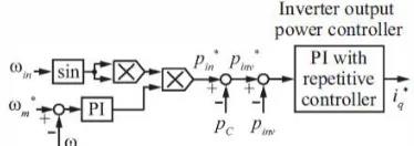
Fig. 5. Control block diagram of inverter output power control
Vector control (or Field Oriented Control) principle makes the analysis and control of Permanent Magnet Synchronous Motor (PMSM) drives system simpler and provides better dynamic response. It is also widely applied in many areas where servo-like high performance plays a secondary role to reliability and energy savings. To achieve the field-oriented control of PMSM, knowledge of the rotor position is required. Usually the rotor position is measured by a shaft encoder, resolver, or hall sensors.
In the PMSM, excitation flux is set-up by magnets; subsequently no magnetizing current is needed from the supply. This easily enables the application of the flux orientation mechanism by forcing the d-axis component of the stator current vector (id) to be zero. As a result, the electromagnetic torque will be directly proportional to the q-axis component of the stator current vector (iq), hence better dynamic performance is obtained by controlling the electro-magnetic torque separately.
This thesis presents the field oriented vector control scheme for permanent magnet synchronous motor (PMSM) drives that regulates the speed of the PMSM, is provided by a quadrature axis current command developed by the speed controller. PI controller cab be preferably used for outer speed control loop but because of its fixed proportional gain constant and integral time constant, the behavior of the PI controllers are affected by parameter variations, load disturbances and speed fluctuation.
To overcome the problem of PI controller, here a Fuzzy controller has been designed and implemented and finally taking the superior performances of PI and Fuzzy controller, a Hybrid PI-Fuzzy controller has been designed and implemented as outer speed loop which provides the reference quadrature axis current to the current controller. The conventional hysteresis band current controller has proven that, it is most suitable for current regulated VSI fed ac drives due to its simplicity and fast speed tracking. However it has certain limitations like large current ripple in steady state and a variable switching frequency operation during motor load changes. So here an adaptive hysteresis current controller in which the hysteresis band is programmed as a function of variation of motor speed and load current has been implemented
II. ELECTROLYTIC CAPACITOR LESS INVERTER AND INVERTER OUTPUT
POWER CONTROL
In a residential air-conditioner application, controlling the compressor with a variable-speed motor drive would allow overall system optimization that could significantly reduce the energy consumption. However, the inverter driven variable-speed motor system requires improving the power quality of the AC sources. Recently, the home electrical appliances apply power factor correction (PFC) circuit in the rectifier. The purpose of PFC is to obtain high power factor, and to achieve the sinusoidal current control in the source side.
ISSN(Online) : 2319-8753 ISSN (Print) : 2347-6710
I
nternational
J
ournal of
I
nnovative
R
esearch in
S
cience,
E
ngineering and
T
echnology
(An ISO 3297: 2007 Certified Organization)
Vol. 5, Issue 3, March 2016
The authors have proposed electrolytic capacitor less single-phase to three-phase power converter for the compressor driven system. The proposed system consists of a single-phase diode rectifier, small film capacitor, three-phase voltage source inverter, IPM motor, and the converter does not have huge energy storage. The previous report in, the high power factor operation has obtained at any load condition. However, there are many current harmonics at the source side; the system could not clear the guideline EN61000-3-2. The previous report in, the harmonics current reduction method has proposed. However, the control method also could not clear the guideline EN61000-3-2.
This project proposes two new control methods to reduce the input current harmonics of the proposed power converter. Firstly, this paper analysis a cause of the increase of the input current harmonics in the proposed power converter. In order to overcome this problem, this paper proposes control methods to reduce the current harmonics distortion. The first method filters out the harmonics of feedback d-q axis current by using harmonics filter. The second method compensates the d-q axis voltage references to reduce the input current harmonics. The d-q axis compensation voltages are obtained by feed forward controller. The experimental results confirm that the proposed method improves the input current waveform and keeps the high power factor control.
Fig. 1 shows a proposed power converter, which consists of a single-phase diode rectifier, small film capacitor, a three-phase voltage-source inverter, and IPM motor. It consists of a few energy storage elements, and the source side power ripple is smoothed by the moment of inertia of the IPM motor. The motor speed is regulated averagely because of the moment of inertia in the motor. There are many torque ripples at the IPM motor. Hence, the proposed power converter applies to the compressor drive system. Small film-capacitor is used to absorb the DC-link current ripple due to the PWM of the three-phase inverter. Fig. 2 shows the control block diagram of the inverter output power controller. As the high power factor operation for the proposed power converter, the inverter output power control is available. In order to obtain high power factor, the inverter output power controls to ripple with twice the synchronized the source voltage frequency. The inverter output power reference Pinv is calculated by subtracting the compensation power of the DC-link capacitor from the input power reference Pin' The input power reference Pin is calculated by multiplying the output of the speed PI controller with sin 2wint generated from the input voltage. Pc is DC-link capacitor power calculated by Vin' The difference between Pin v and Pp 'in v is the inverter output power error. This error is controlled by the inverter output-power controller, and its output is the q-axis current command 'i.
CURRENT HARMONICS OF PROPOSED POWER CONVERTER
Typically, a conventional inverter system having large electrolytic capacitor and a PFC circuit can control input current waveform. The PWM switching pattern in the inverter and the motor side harmonics does not influence to the source side current waveform because of the large electrolytic capacitor. However, the proposed electrolytic capacitor less power converter is affected by the motor side harmonics because of small DC-link capacitor. This chapter clarifies the influence of motor side harmonics on the input current harmonics.
Spatial Harmonics of IPM Motor
A back EMF of the IPM motor has spatial harmonics with the amplitude and frequency, proportional to motor speed, because the shape of the rotor has not a sine wave.Fig. 3 show the back EMF waveform of the tested IPM motor.
III. POWER FACTOR CORRECTION
ISSN(Online) : 2319-8753 ISSN (Print) : 2347-6710
I
nternational
J
ournal of
I
nnovative
R
esearch in
S
cience,
E
ngineering and
T
echnology
(An ISO 3297: 2007 Certified Organization)
Vol. 5, Issue 3, March 2016
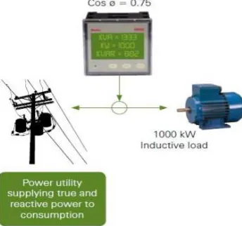
POWER FACTOR:
Input power factor of electrical power system is defined as
For purely sinusoidal voltage and current,
PF= cosФ
Let us consider for an input voltage of V and a line current of I,VI cosФ , VI sin and VI is the active power in kW, reactive power in kVAR and apparent power in KVA. Power factor is the measure of how much the input line current and input voltages are distorted from the original shape and phase shift between them. Consider an inductor circuit, which draws a current I from the supply mains lagging behind the supply voltage V by an angle.
Where open electricity markets have been introduced, the supply of electrical energy becomes competitive between the supply utilities. Although private distribution companies are obligated to run a profitable and successful business, they are also committed to maintain the quality of supply at a high level. Competition in an open electricity market creates new opportunities for even better quality of supply of electricity. One very important aspect of improving quality of supply is the control of power factor. Low power factor means poor electrical efficiency. The lower the power factor, the higher the apparent power drawn from the distribution network. This means that the supply company must install larger generation capacity, larger size transmission lines and cables, transformers and other distribution system devices, which otherwise would not be necessary. This results in a much higher capital expenditures and operating costs for the Electricity Supply Company, which in many cases is passed on to the consumer in the form of higher tariff rates. This is the main reason behind why the Electricity Supply Companies in modern economies demand reduction of the reactive load in their networks via improvement of the power factor. In most cases, special reactive current tariffs penalize consumers for poor power factors Electrical load types Loads on an electrical distribution system can becategorized as resistive, inductive and capacitive. Under normal operating conditions certain electrical loads (e.g. transformers, induction motors, welding equipment, arc furnaces and fluorescent lighting) draw not only active power (kW) from the supply, but also inductive reactive power (kVAr). All inductive loads require active power: kW to actually perform the work, and reactive power (kVAr) to maintain the electromagnetic field. This reactive power is necessary for the equipment to operate but it imposes an undesirable burden on the supply.
ISSN(Online) : 2319-8753 ISSN (Print) : 2347-6710
I
nternational
J
ournal of
I
nnovative
R
esearch in
S
cience,
E
ngineering and
T
echnology
(An ISO 3297: 2007 Certified Organization)
Vol. 5, Issue 3, March 2016
Fig. 7. With Power Factor Correction
Fig. 7. Schematic Block diagram for Drive System
3.2 POWER FACTOR CORRECTION
Power Factor Correction and Variable Speed Drives
As a general rule, standard power factor correction systems should not be used when there are Variable Speed Drives (VSD’s) connected to the same point of connection unless some precautions are taken.
Two situations arise when using power factor correction systems:
1. Installation of the power factor correction between the VSD and the motor, and
2. Installation of the power factor correction on the line side of the VSD
In the first case, power factor correction should not in any case be connected between the output of the VSD and the motor. In typical DOL situations, some installations will have a fixed KVAR value of capacitors sized to counteract the motors inductive reactance hence increase the power factor on the supply line. Be cautious when replacing DOL components with a VSD – if there are PF correction capacitors connected to the motor remove them as premature damage to the inverter and motor will occur due to the high frequency switching voltage occurring on the output of the inverter.
Most capacitors are not designed to withstand the high switching currents produced by VSD’s. In the second case, power factor correction can be installed on the line side of the VSD but only under certain conditions. In all cases, VSD’s produce a certain level of harmonic distortion back into the main supply. This harmonic distortion is in the form of both THID (total harmonic current distortion) and THVD (total harmonic voltage distortion) and the levels of this THD is dependent upon the size of the drive, the supply transformer impedances, short circuit levels, primary and secondary voltage levels plus cable lengths and cable size.
ISSN(Online) : 2319-8753 ISSN (Print) : 2347-6710
I
nternational
J
ournal of
I
nnovative
R
esearch in
S
cience,
E
ngineering and
T
echnology
(An ISO 3297: 2007 Certified Organization)
Vol. 5, Issue 3, March 2016
circuits of the inverter and the energy behind the impulses is much greater due to the energy storage of the capacitors. This will in turn prematurely damage the input rectifier of the VSD causing costly repairs.
In addition, the increased current and voltage transients on the line side are passed back through the PFC capacitors causing increased operating voltage and current, which produces higher operating temperatures and may cause premature failure of the capacitors. By reducing the effects of THVD and THID through the use of input reactors, harmonic filters, active harmonic filtering on the line side of the VSD or using a 12-pulse rectifier (or even better an Active Front End solution), this reduces the effect of the transient impulses which can damage both the VSD and the PFC capacitors. Ensure that the capacitors used in the PFC system have a harmonic tolerance level greater than the harmonic distortion produced by the VSD installation.
Power Factor Correction and Soft Starters
Individual or ‘Static’ power factor correction capacitors can be used with soft starters provided they are installed on the input side of the soft starter and switched via a dedicated contactor only after the motor has reached full speed. The contactor shouldbe AC6 rated for the motor full load current. Automatic or ‘Bulk’ power factor correction systems make use of a power factor controller to monitor changing power factor and automatically switch capacitors as needed. When used with a soft starter the automatic switching of capacitors should be inhibited until the motor is running at full speed. When a soft starter is installed in close proximity to a power factor correction capacitors (less than 50m) and used without a main contactor, the switching of capacitors whilst the soft starter is not passing motor current can also lead to premature starter failure. The use of a main contactor is therefore recommended when;
IV. OVERVIEW AND DYNAMIC MODELLING OF IPM DRIVE SYSTEM
This chapter deals with the description and design of dynamic mathematical model of the permanent magnet synchronous motors drive system for its vector control analysis before proceeding to design control and observation algorithms for them.
Permanent Magnet Synchronous Motor Drive System:
The motor drive consists of four main components, the PM motor, inverter, control unit and the position sensor. The components are connected as shown in Fig. 4.1.
Mathematical Model of IPMSM:
The mathematical model for the vector control of the PMSM can be derived from its dynamic d-q model which can be obtained from well-known model of the induction machine with the equation of damper winding and field current dynamics removed. The synchronously rotating rotor reference frame is chosen so the stator winding quantities are transformed to the synchronously rotating reference frame that is revolving at rotor speed.
The model of PMSM without damper winding has been developed on rotor reference frame using the following assumptions:
1) Saturation is neglected.
2) The induced EMF is sinusoidal.
3) Core losses are negligible.
ISSN(Online) : 2319-8753 ISSN (Print) : 2347-6710
I
nternational
J
ournal of
I
nnovative
R
esearch in
S
cience,
E
ngineering and
T
echnology
(An ISO 3297: 2007 Certified Organization)
Vol. 5, Issue 3, March 2016
It is also be assumed that rotor flux is constant at a given operating point and concentrated along the d axis while there is zero flux along the q axis, an assumption Similarly made in the derivation of indirect vector controlled induction motor drives. The rotor reference frame is chosen because the position of the rotor magnets determine independently of the stator voltages and currents, the instantaneous induced emf and subsequently the stator currents and torque of the machine. When rotor references frame are considered, it means the equivalent q and d axis stator windings are transformed to the reference frames that are revolving at rotor speed. The consequences is that there is zero speed differential between the rotor and stator magnetic fields and the stator q and d axis windings have a fixed phase relationship with the rotor magnet axis which is the d axis in the modeling. The stator equations of the induction machine in the rotor reference frames using flux linkages are taken to derive the model of the IPMSM as shown in Fig.2.2:
Equivalent circuit of PMSM:
For analysis purpose equivalent circuits of the motors are used for study and simulation of motors. From the d-q modelling of the motor using the stator voltage ed-quations the ed-quivalent circuit of the motor can be derived. Assuming rotor d axis flux from the permanent magnets is represented by a constant current source as described in the following equation λf= Ldmif , following figure can be obtained from shown as fig 2.3 and fig.2.4. The equivalent circuits are
1. Dynamic stator q-axis equivalent circuit
2. Dynamic stator d-axis equivalent circuit
Vector Control or Field Oriented Control Analysis:
This control strategy was developed prominently in the1980s to meet the challenges of transient condition analysis and oscillating flux with torque responses in inverter fed induction and synchronous motor drives during transient as well as steady state condition. The inexplicable dynamic behavior of large current transients and the resulting failure of inverters was a curse and barrier to the entry of inverter fed ac drives into the market. Compared to these ac drives, the separately excited dc motor drives were excellent dynamic control of flux and torque. The key to the dc motor drives performance is its ability to independently control the flux and torque.
V. CURRENT HARMONICS OF PROPOSED POWER CONVERTER
ISSN(Online) : 2319-8753 ISSN (Print) : 2347-6710
I
nternational
J
ournal of
I
nnovative
R
esearch in
S
cience,
E
ngineering and
T
echnology
(An ISO 3297: 2007 Certified Organization)
Vol. 5, Issue 3, March 2016
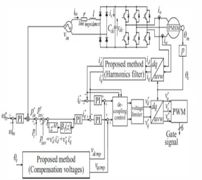
Fig. 8. System configuration of proposed control method
A. Harmonics Reduction Method using Harmonics Filter
Fig. 5 shows the control block diagram of the first method. The proposed method filters out the harmonics of feedback d-q axis current by notch filter. In order to apply the filter to the d-q axis frame, the filter is designed for the (n+ l)th harmonics as follows.
Where, n is the targeted harmonic order number, Wm is the motor speed in rpm, and p is pole number. In this paper, the largest harmonic content of tested motor is the fifth. Hence, the filter is designed to sixth order.
31
B. Harmonics Reduction Method using Compensation Voltages
Fig.3.2 shows the control block diagram of the second method. The proposed method compensates the d-q axis voltage references to reduce the input current harmonics. The d-q axis compensation voltages Vdemp and vqemp are obtained by feed forward controller. The compensation voltages Vdemp and vqemp are calculated by using following equations.
ISSN(Online) : 2319-8753 ISSN (Print) : 2347-6710
I
nternational
J
ournal of
I
nnovative
R
esearch in
S
cience,
E
ngineering and
T
echnology
(An ISO 3297: 2007 Certified Organization)
Vol. 5, Issue 3, March 2016
fifth harmonics shown in Fig. Hence, n is set at 5. ¢d and ¢q are phase differences between electrical rotor position 8e obtained fromthe encoder. Kd and Kq are the gain of the compensation voltages. In this paper, ¢d, ¢q, Kd and Kq are obtained by off-line experimental test
C. Proposed Control Block Diagram and Design of d-q axis Current Controller
Fig. 7 shows the diagram of the entire circuit with the proposed control method using the harmonics filter and compensation voltages. The currents id and iq are obtained by coordinate conversion from the detected currents iu and iw, respectively. The harmonics filter of the proposed method filters out harmonics current of id and iq•
These currents are subtracted from the reference currents i'd and iq, and each current is regulated by the PI controller. The compensation voltages of the proposed method are added to the output of the PI current regulator.
In this project, the d-q axis proportional gain Kdp and Kqp in the PI current regulator are designed as follows
Where, We is cut-off frequency of the current controller. Kdp is not same as Kqp because of Ld and Lq. The harmonic content of the motor current passes this current controller and becomes the inverter voltage references. The harmonics of d-q axis voltage references v'dh' and v’ qh.
VI. RESULTS
ISSN(Online) : 2319-8753 ISSN (Print) : 2347-6710
I
nternational
J
ournal of
I
nnovative
R
esearch in
S
cience,
E
ngineering and
T
echnology
(An ISO 3297: 2007 Certified Organization)
Vol. 5, Issue 3, March 2016
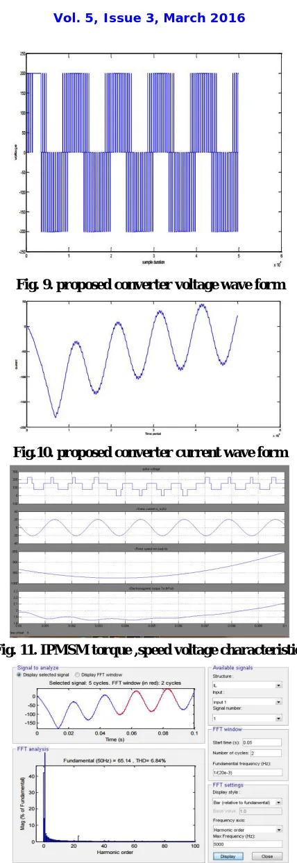
Fig. 9. proposed converter voltage wave form
Fig.10. proposed converter current wave form
Fig. 11. IPMSM torque ,speed voltage characteristics
ISSN(Online) : 2319-8753 ISSN (Print) : 2347-6710
I
nternational
J
ournal of
I
nnovative
R
esearch in
S
cience,
E
ngineering and
T
echnology
(An ISO 3297: 2007 Certified Organization)
Vol. 5, Issue 3, March 2016
VII. CONCLUSION
This project proposes two new control methods to improve the input current waveforms of the electrolytic capacitor less power converter. Firstly, this paper analyzed a cause of the input current harmonics aims to the back EMF of the IPM motor and the d-q axis current controller. The proposed method reduces the harmonic content by the spatial harmonics of the motor. The proposed methods filter out the harmonics of feedback d-q axis current and compensate the d-q axis voltage references to reduce the input current harmonics. The d-q axis compensation voltages are obtained by feed forward controller. The effectiveness of the proposed method has been verified by experiments in comparison with the conventional method. These two control methods clear the guideline EN61000-3-2. The maximum power factor of the proposed method is 98.47% and the THD of the input current is 6.84%.
REFERENCES
[1]Gao and Y. Hu, "Direct Self-Control for BLDC Motor Drives Based on Three-Dimensional Coordinate System", IEEE Trans. On Ind. Electron., vol. 57, no. 8,
pp.2836-2844, 2010.3158
[2]S. Shao, E. Abdi, and R. McMahon, "Low-Cost Variable Speed Drive Based on
aBrushless Doubly-Fed Motor and a Fractional Unidirectional Converter " , IEEE Trans. Ind. Electron., vol. 59,no.!, pp. 317-325 (2012)
[3]K. Kondo and H. Kubota, "Innovative Application Technologies ofAC Motor Drive Systems", IEEl lournal of Industry Applications, vol. 1, no. 3, pp. 132-140, 2012.
[4]M. K. H. Cheung, M. H. L. Chow, and C. K. Tse, "Design and Performance Considerations of PFC Switching Regulators Based on Noncascading Structures", IEEE Trans. on Ind. Electron., vol. 57, no. II, pp. 3730-3745, 2010.
[5]H. L. Cheng, Y. C. Hsieh, and C. S. Lin, "A Novel SingleStage High-Power-Factor ACIDC Converter Featuring High Circuit Efficiency", IEEE Trans. Ind. Electron., vo1.58, no.2, pp.524-532 (2011)
[6]Z. Li, C. Y. Park, 1. M. Kwon, and B. H. Kwon, "High-PowerFactor Single-Stage LCC Resonant Inverter for Liquid Crystal Display Backlight" , IEEE Trans. Ind. Electron., vo1.58, no.3, pp.1008-1015 (2011)
[7]C. Larouci, T. Azib, A. Chaibet and M. Boukhnifer, "Control of a Flyback Converter in Mixed Conduction Mode: Influence on the Converter Design Using Optimization under Constraints " , IEEll. Ind. Appl., vol. 2, no. 3, pp. 132-140 (2013)
[8]M. Daniele, P. K. lain, and G. loos, "A single-stage power-factor corrected ACIDC converter", IEEE Trans. Power Electron., vol. 14, no. 6, pp. 1046-1055, Nov. 1999.
[9]P. 1. Grbovic, P. Delarue, P. Le Moigne, and P. Bartholomeus, "A Three- Terminal Ultracapacitor-Based Energy Storage and PFC Device for Regenerative Controlled Electric Drives" , IEEE Trans. on Ind. Electron., vol. 59, no. I, pp. 301-316 (2012)
[10]K. Inazuma, H. Utsugi, K. Ohishi, and H. Haga, "HighPowerFactor
Single-phase Diode Rectifier Driven by Repetitive ControlledTPM Motor", IEEE Trans. on Industrial Electron., vol. 60, no. 10, pp. 4427-4437, 2013.