77 Available online at www.ijiere.com
International Journal of Innovative and Emerging
Research in Engineering
e-ISSN: 2394 - 3343 e-ISSN: 2394 - 5494
Solar Panel Using Inverter with Level Indicator
Rajesh Singh Shekhawat
a, Ruchika Singh Rao
b, Kajal Kumari
cand Vinod Kumar
d aAssistant Professor, BKBIET, Pilani, Rajasthan, Indiab, c & dStudent, BKBIET, Pilani, Rajasthan, India
ABSTRACT:
This paper reviews about working of solar panel, level indicator circuit, solar charger circuit and inverter circuit. The most important indicator to characterize the advances in inverter technology is level indicator which shows the amount of charge left in the battery. For charging the battery both AC mains and solar energy can be used. This paper presents a higher functionality of inverter circuit. This paper also presents a small description of the solar power system project and its main components.
Keywords: Inverter, photovoltaic effect, solar charger, solar panel, level indicator.
I.INTRODUCTION
In this paper we are generating electricity with the help of solar radiations. When solar radiation falls on solar plate then with the help of photovoltaic effect it converts it into electricity. This DC power can be stored into battery with the help of solar charger circuit. Further this DC power can be used by converting it into AC power with the help of inverter circuit. [1]
II. SOLAR CHARGER
Solar charger is a device which uses solar energy in the form of radiations to supply electricity to devices or to charge a battery. Lead acid battery or Ni-Cd battery banks can be charged with the help of solar charger circuit. For this at stationary locations series of solar cells are installed. These solar cells can be directly connected to battery banks to store energy for off peak hours. They can also be used in peak hours for saving energy during daytime. The range of charging voltage produced from solar panel depends upon the intensity of the sun. Thus to protect the solar charger circuit from overcharging or over voltages a voltage regulator must be used along with the solar charger circuit. [2]
Figure 1. Circuit diagram of solar charger circuit [14]
III.COMPONENTS USED IN SOLAR CHARGER CIRCUIT
A. Solar Panel (18V)
78 B. Diode (1N4001)
Diode is a rectifying device which conducts only from anode to cathode. In case of current flowing from cathode to anode diode behaves as open circuited. In this paper diode is used so that current could flow from solar panel to battery and not from battery to solar panel otherwise solar panel would get damaged. These diodes have many features like low forward voltage drop, high surge current capability and diffused PN junction. [4]
C. IC (LM317T)
This IC is a voltage regulator IC which is capable of supplying more than 1.5 A. To set its output voltage it requires only two external resistors. It various features are that it could limit current as well as provide thermal overload protection and safe operating area protection. [5]
D. BJT (BC548)
BJT BC548 is a NPN silicon transistor. This transistor can be used for both amplification and switching purpose. [6] Its maximum DC current gain is 800. The different transistors of this series are BC548A, BC548B and BC548C which vary in terms of current gain and other characteristics. This transistor requires biasing to operate in the desired region i.e., a fixed DC voltage. This transistor is used in common emitter configuration for amplifiers. It can be easily turned off by removing base signal.
E. Resistor (0.5 ohm, 100 ohm, 120 ohm, 470 ohm)
Resistor is a component that provides electrical resistance in a circuit. It reduces the amount of current and voltage in the circuit. Fixed resistors are the ones whose value changes slightly with temperature, time or operating voltage and variable resistors are the ones whose value changes which could further be used as sensing device for light, heat, chemical activity, humidity or force. [7] In this circuit various resistors of different ratings are used. Those are resistors of 0.5 ohm, 100 ohm, 120 ohm and 470 ohm.
F. Potentiometer (1K)
A potentiometer is a kind of three terminal resistor with sliding or rotating contact used for adjustable voltage division. It is used for measuring electric potential (voltage). [8] In this circuit potentiometer used is of 1K.
G. Capacitor (0.22µf)
Capacitor is a component which is used to store electrical charge. Capacitor is mainly used for power factor correction. Basically, a capacitor consist of two or more parallel conductive plates which are separated from each other either by air or some good insulating material. This insulating layer between capacitor plates is known as dielectric which blocks DC current but allows AC current to pass through it. [9] The capacitor used in this circuit is of 0.22 µf.
H. Battery (12V)
A battery is a device that converts stored chemical energy into electrical energy with the help of electrochemical cells. Battery is a collection of cells. Each cell has a positive and a negative terminal. Terminal marked as positive is at higher potential with respect to terminal marked as negative. When cell is connected to an external circuit the terminal marked as positive behaves as a source of electrons and when battery is connected to an external circuit, electrolyte move as ions for completing chemical reaction to deliver energy to external circuit. In this paper the battery used is AT12-7.6(12V7.6AH). It has many applications like UPS system, solar lighting & LED lighting. [10]
IV.WORKING OF SOLAR CHARGER CIRCUIT
When solar radiation falls on solar plate then it absorbs sun rays as a source for generating electricity. These sun rays are the light energy (photons) directly coming from the sun. In this circuit a diode of series 1N4001 is placed which is used to give a unidirectional flow to current flowing in the circuit i.e., current could only flow from solar panel to battery and not from battery to solar panel. After the battery an IC of series LM317T is used, which is working as a voltage controlling device. It controls the voltage been generated. If the voltage generated is more than 18 Volts then it will trip the resistor of 0.5 ohm due to which circuit will become incomplete and due to this incomplete circuit current will stop flowing through the circuit. In this the main motive behind tripping the resistor of 0.5 ohm was to protect the battery used in the circuit. Further a potentiometer of 1K is used in the circuit. It is only used to set voltage according to our requirement by which battery would we charging. Here in this paper we are adjusting the charging voltage as 12 Volt as the capacity of the battery used is 12 Volt. In this circuitry a BJT is also used. Since a BJT is a current controlling device, here it is used in this circuitry for same purpose. Here the BJT of series BC548 is used to control the current flowing due to conversion of solar radiations into electricity. Here a capacitor of 0.22 µF is used to operate this BJT. The current flowing through the circuitry depends upon solar watts. The solar panel used in the paper is of 37 Watts due to which current flowing is 3 Amperes when it charges.
V. PRACTICAL CIRCUIT OF SOLAR CHARGER
79
VI.INVERTER
Inverter is a device that converts Direct Current (or DC) to Alternating Current (or AC) using transformers, switching circuits and control circuits.[11] Home inverters or home UPS takes the DC power from the batteries and converts it into AC power used by the load connected at home. Similarly, an “Off Grid” solar inverter operates. In case of “Grid Connected” solar inverter the DC power is generated from the solar panels and AC power is given to the grid. In case of “Grid Connected” solar inverter when the power is coming from the grid, the UPS/inverter system charges the batteries using the power coming from the grid. When the power coming from the grid is off, then the inverter takes the DC power from the batteries and converts it into AC to supply it to appliances. An automatic switch is used to sense whether the power is coming from the grid and if not then it switches the UPS into battery mode. [2]
Figure 3. Circuit diagram of inverter circuit [15]
VII. COMPONENTS USED IN INVERTER CIRCUIT
A. IC (CD4047)
It is a low power Monostable/Astable multivibrator. It can operate in only one mode at a time. It requires an external capacitor (between pin 1 & 3) and an external resistor (between pin 2 & 3) to determine the output pulse width in the monostable mode, and the output frequency in the as astable mode. Its various features are wide supply voltage range: 3V to 15V, high noise immunity, low power compatibility, low power consumption and only one external R and C required. [11]
B. MOSFET (IRFZ44)
MOSFET IRFZ44 is an n-channel MOSFET which is used for both amplifying and switching purpose. MOSFET’s are the most common transistors used because of its main advantage that it requires lesser amount of current to turn on while it delivers much higher amount of current to load. It has maximum VDSS as 55 V and can handle continuous drain current up to 49 A.
C. Transformer (12-0-12)
A transformer is a static device that transfers electrical energy from one circuit to another through electromagnetic induction without the change in frequency. Transformers are used in circuits to increase or decrease the voltages value. In this paper the transformer used is of 12-0-12 Volt and 5 A. It has 240 V primary windings and centre tapped secondary winding. This transformer act as a step down transformer reducing AC - 240 V to AC - 12 V. [5] D. Resistors (100 ohm, 1K ohm, 18K ohm)
In this circuit the resistors of different ratings are used. Those are resistors of 100 ohm, 1K ohm and 18K ohm. E. Capacitor (0.22µF)
In this circuit the capacitor used is of 0.22 µF.
VIII.WORKING OF INVERTER CIRCUIT
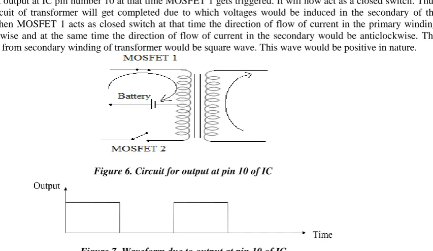
80 Figure 4. Output wave of IC
Figure 5. Circuit for output
When we get output at IC pin number 10 at that time MOSFET 1 gets triggered. It will now act as a closed switch. Thus the primary circuit of transformer will get completed due to which voltages would be induced in the secondary of the transformer. When MOSFET 1 acts as closed switch at that time the direction of flow of current in the primary winding would be clockwise and at the same time the direction of flow of current in the secondary would be anticlockwise. The output obtained from secondary winding of transformer would be square wave. This wave would be positive in nature.
Figure 6. Circuit for output at pin 10 of IC
Figure 7. Waveform due to output at pin 10 of IC
When we get output at IC pin number 11 at that time MOSFET 2 gets triggered. It will now act as a closed switch. Thus the primary circuit of transformer will get completed due to which voltages would be induced in the secondary of the transformer. When MOSFET 2 acts as closed switch at that time the direction of flow of current in the primary winding would be anticlockwise and at the same time the direction of flow of current in the secondary would be clockwise. The output obtained from secondary winding of transformer would be square wave. This wave would be negative in nature.
81 Figure 9. Waveform due to output at pin 11 of IC
Thus the net output obtained would be complete square wave. Since this output obtained is an alternating output but not a smooth one thus for it we use a capacitor with switch.
Figure 10. Waveform of total output
IX.PRACTICAL CIRCUIT OF INVERTER
Figure 11. PCB designed inverter circuit
X. LEVEL INDICATOR
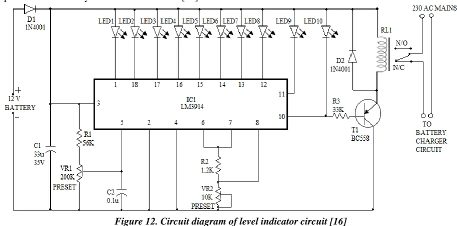
The charge is stored in battery by converting sunlight into electricity with the help of photovoltaic system. [12] The battery level indicator indicates the status of the battery by glowing different LED’s. This circuit includes total 10 LED’s. So if first LED is glowing then the amount of charge left in the battery is 10% and if fifth LED is glowing then the amount of charge left in the battery is 50%. Thus, by using this circuit we can increase the life time of a battery. The main component of this battery circuit is LM3914 IC. [18]
Figure 12. Circuit diagram of level indicator circuit [16]
82 A. IC (LM3914)
This IC is used to find the status of 12V battery. This IC takes input as analog voltage and drives LED’s according to the input voltage. In this circuit there is no need of resistors in series with LED’s because current flowing through the LED is regulated by the IC used in the circuit. It is a milli volt measuring IC which is able to convert milli volt input into LED indication. It can operate for supply voltage between 3V to 25V DC. For this a resistor of 1.2 kΩ is connected between pins 6, 7 & ground. 56 kΩ resistor and 200 kΩ potentiometer forms a voltage divider network. [13]
B. LED
LED’s are used to indicate the amount of charge left in the battery. For different amount of voltage different LED glows. When there is minimum charge in the battery at that time LED1 glows. And as the charge in the battery increases next LED glows.
Table 1. Status of LED’s according to battery level
Battery Level Percentage Status of LED’s
1.2V 10 LED1-ON
2.4V 20 LED2-ON
3.6V 30 LED3-ON
4.8V 40 LED4-ON
6.0V 50 LED5-ON
7.2V 60 LED6-ON
8.4V 70 LED7-ON
9.6V 80 LED8-ON
10.8V 90 LED9-ON
12V 100 LED10-ON
In this paper three different colours of LED’s are used to indicate the status of battery. LED1-LED3 are of red colour which indicates that the charge left in the battery is between 0-30%, LED4-LED6 are of yellow colour which indicates that the charge left in the battery is between 40-60% and LED7-LED10 are of green colour which indicates that the charge left in the battery is between 70-100%. [14]
C. Resistors
In this circuit the resistors of different ratings are used. Those are resistors of 56kΩ, 1.2kΩ and 33kΩ. D. Potentiometer
In this circuit the potentiometer of different ratings are used. Those are 200 K and 10 K potentiometers. E. Capacitor
In this circuit the capacitors of different ratings are used. Those are 33µf and 0.1 µf. F. Battery
Dc supply is given from a 12V battery.
XII. WORKING OF LEVEL INDICATOR CIRCUIT
The circuit gets the power for its operation from the 12V battery as well as AC mains. When supply (AC mains supply) is coming at that time battery would get charged as well as load would be driven with the AC mains supply. But when there is no light at that time relay would operate and the load would be driven with the help of battery. When battery is fully charged LED10 glows. And as the charge of battery is continuously used to drive the load thus charge of the battery decrease and thus at 90% charge left LED9 glows. Similarly at 80% charge left LED8 glows and so on. When there is minimum charge left in the battery at that time LED1 glows. Diode D1 is used to protect the circuit from reverse-polarity battery connection. When the battery gets fully charged, LED10 glows which drives the transistor which finally energise the relay. This stops further charging of battery.
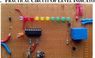
XIII. PRACTICAL CIRCUIT OF LEVEL INDICATOR
83
XIV.CONCLUSIONS
A solar panel using inverter with level indicator had successfully been designed and developed. Solar charger was used to store DC power which was generated by photovoltaic effect of solar panel. Inverter circuit is used to convert DC power into AC power which is used to drive the loads. Level indicator circuit helps to determine the amount of charge left in the circuit. This prototype can easily be implemented in real life to increase the efficiency of solar inverter. By using relays the working of the circuit can be further enhanced as it would then become completely automatic. Another room of improvement is to use microcontrollers instead of relays.
ACKNOWLEDGMENT
I am thankful to Dr. P S Bhatnagar (Director, BKBIET, Pilani) his true help & providing the resources on completion of paper. Last but not least, I pay my sincere thanks and gratitude to Prof Dr. L .Solanki (Principal Academic, BKBIET, Pilani) for his valuable suggestions & Encouragement.
REFERENCES
[1] Nishit Kapadia, Amit Patel, Dinesh Kapadia, “Simulation and design of low cost single phase solar inverter”, International Journal of Emerging Technology and Advanced Engineering, ISSN 2250-2459, Volume 2, pp 158-159, February 2012.
[2] Vikas Kulkarni, Rajesh Nehete, “Simulation and Analysis of Photo-Voltaic (PV) based Solar Inverter System”, International Journal of Soft Computing and Engineering, ISSN: 2231-2307, Volume 3, pp 114, January 2014.
[3] Paul Hersch, Kenneth Zweibel, Basic Photovoltaic Principles and Methods, United States of America, pp 7-8, February 1982.
[4] Divakar Mani, “Diode Time”, Hochschule Furtwangen University, pp 3, 2013.
[5] Manisha Ghodke, Sujata Naduvinamni, Anusha Kanchagar, Chaitra Patil, Akshata Miskin, “ Design and development of stabilized regulated fixed and variable DC power supply unit with short circuit protection”, Proceeding of NCRIET & Indian J. Scires, ISSN: 2250-0138, pp 3-4, 2015.
[6] S. Jeneeth Subashini, R. Gokula Krishnan, S. Karthick, V. Arun Kumar, “Sound heard dimming light circuit with three states used for domestic alerts, roofings in hotels kids corner”, International Journal of Electrical and Electronics Research, ISSN: 2348-6988, pp 293 ,September 2014.
[7] Abdalla Obeidat, Maen Gharaibeh, Manal Al-Ali, Akram Rousan, “Evolution of a current in a resistor”, An International Journal for Theory and Applications, Volume 14,pp 247-248, November 2011.
[8] Ray P. Teele, Shuford Schuhmann, “A potentiometer for measuring voltages of 10 microvolt to an accuracy of 0.01 microvolt”, Part of Journal of Research of the National Bureau of Standards, Volume 22, pp 431-432, April 1939. [9] M Jayalakshmi, K Balasubramanian, “Simple Capacitors to Supercapacitors - An Overview”, International Journal
of Electrochemical Science, pp 1196-1198, October 2008.
[10] Andreas Oberhofer, “Energy Storage Technologies & Their Role in Renewable Integration”, pp 10-11, July 2012. [11] Devyani K. Patil, Namrata N. Gupta, Rytuja M. Bangale, Varsha D. Chordhari, Shalaka N. Chaphekar, “ Single phase
pure sine wave Inverter (Hardware and software)”, International Journal of Scientific and Engineering Studies, ISSN: 2349-8862, Volume 2,pp 35-36, May 2015.
[12] Ankita Dhakate, “Power Optimization of Battery Charging System Using FPGA Based Neural Network Controller”, International Journal of Engineering Research and Applications, ISSN: 2248-9622, Volume 4, pp 112, August 2014. [13] C. Sathian, B. Kumar, C. Raju, “Belt Slackness Detection for the Automobile System”, Bonfring International Journal
of Industrial Engineering and Management Science, Volume 2, pp 4, March 2012.
[14] ‘Circuit diagram’, “Solar Battery Charger” http://www.circuitdiagram.org/solar-battery-charger-circuit.html [15] ‘Circuits gallery’,“Circuit diagram of Dc to Ac Inverter Circiut”
http://www.circuitsgallery.com/2012/07/simple-low-power-inverter-6v-dc-to-230v.html
![Figure 1. Circuit diagram of solar charger circuit [14]](https://thumb-us.123doks.com/thumbv2/123dok_us/8874784.1816208/1.595.147.451.476.633/figure-circuit-diagram-solar-charger-circuit.webp)
![Figure 3. Circuit diagram of inverter circuit [15] VII. COMPONENTS USED IN INVERTER CIRCUIT](https://thumb-us.123doks.com/thumbv2/123dok_us/8874784.1816208/3.595.103.542.165.352/figure-circuit-diagram-inverter-circuit-components-inverter-circuit.webp)