Copyright © 2015 IJECCE, All right reserved
A Survey on Network Access Technologies for Global
Network System Integration
Eke Vincent O. C.
Department of Computer Science,Ebonyi State University, Abakaliki. Ebonyi State, Nigeria Email: [email protected]
Eke Christopher Ifeanyi
Computer Science Department, Federal University Lafia Nigeria Email: [email protected]Abstract – Requirements analysis is the first technical step in the system engineering process. In most cases, it should capture what the users and the developers require. A survey is essential to ensure that the developer and the user have the same perception of the system. Global communications network Access techniques provide ubiquitous network access to the wireless users, enabling services that were available only to wire line users as well as mobile users anywhere and anytime in the world. In this paper, we present the Global Access technologies ranging from third generation (3G) networks to satellite communications network. This survey investigates the satellite and terrestrial networks in terms of capabilities, coverage, cost, benefits and limitations. The survey includes a very detailed overview of the basic operations, features, and equipment of both satellite and some selected terrestrial communications networks.
Keywords – ATM Satellite Network, Global Network System Integration, Large Geographical Coverage, Mobile Internet, Network Access Technology.
I.
I
NTRODUCTIONThe economics of wire line access are such that most of the world populations will never get access to advanced digital applications through terrestrial means. This is because most existing wire line networks will not support advanced applications[1]. However, as advanced information services become increasingly essential to economic development, education, healthcare, and public services, the wire line broadband (fiber) networks in advanced urban areas will derive demand for global access to broadband applications, and the gap between the urban and rural areas will widen [1]. In the last two decades, wireless communications has emerged as a technological marvel, allowing for easy access to information, computation and communications in anywhere and anytime. Increasingly, wireless cellular will be the access technology of first choice in rural and remote areas. Cellular is limited to narrowband applications. In order to decrease the digital divide, it is of a paramount importance to provide business, healthcare and personal broadband applications to remote regions and less developed countries [2].
In this context, low earth orbit satellite constellations with Intersatellite networks are particularly attractive if they are expected to provide global access to asymmetric applications such as data, audio, video streaming, bulk data transfer and multimedia applications with limited interactivity as well as the real-time broadband interactive services. In so doing, satellite networks have a crucial role to play to the possibility of providing different types of
traffic to a large geographical coverage [2]. Such satellite communications system comprises of satellite, ground stations, ground to satellite links and inter satellite links [2].
Providing services to mobile users from any place and at anytime is the “central requirement” in the current information and communications technology market [3]. To meet this requirement, Internet connections offer a method to achieve universal services anywhere in the world. Although, the Internet is a giant packet-switched network that consists of fixed networks, the evolution of fixed networks (PSTN, ISDN, Frame-relay, X.25, and ATM) and mobile networks (GSM, GPRS, UMTS,) are being converged with IP as the common transport protocol. The convergence of all these networks is needed to deliver end-to-end seamless services with high bandwidth in real-time, security, and QOS built-in [4]. Hence, there is the need to design an IP-core network to acquire connection-oriented properties, properties.
Despite the increasing availability of network resources (both in terms of capacity and variety of offered technologies), and proliferation of mobile devices, several interfaces (such. as WLANS, Internet, UMTS, and Bluetooth), network connectivity cannot be guaranteed at any place and at any time [3]. Ideally, such pervasive networked systems should be able to adapt to changing user requirements and even anticipate their future needs and preferences [3].Also, it has been noted in [5] that when technologies with widely different characteristics (bandwidth ,QOS support, pricing) co-exist and convergence areas overlap, restricting usage to one single interface at a time limits the flexibility available to the end users in making the best use of all available resources.
Copyright © 2015 IJECCE, All right reserved technologies, In section 4,we present a comparison of
these technologies and conclude our paper in section five.
II.
S
YSTEMA
NALYSIS OF THES
ATELLITEATM
N
ETWORKThe recent literature contains numerous proposals for moving the centralized earth-based traditional ATM paradigm into “the sky” by placing ATM switches into the satellites. A LEO satellite features low propagation delays as well as low power requirements, allowing handheld devices to interface directly with the system. The communication infrastructure of the future will be characterized by the seamless integration of IEO satellite networks with broadband networking techniques in order to support multimedia services and provide global coverage as well as different types of traffics to be heterogeneously distributed to the world population [2]. The key role in this integration effort will be played by the development of ATM as the basic transport mechanism in support of broadband Internet, broadband ISDN, and other technologies. In 2.1, we provide an overview of the evolutionary trends of satellite development. In 2.2, we provide reasons for and against IP-routing onboard and the solution. In 2.3, we discuss the satellite ATM architecture and protocol stack.
2.1 The Evolutional Trends of Satellite Development
Satellite-basednetworking has developed in complexity over the years, rising and building upon established network at the various networking layers as described by the ISO Reference Model [7]. Networking using satellites began by using the Geostationary orbit to complex media-access control (MAC) schemes (e.g. slotted ALOHA and its variants for use with VSAT Networks) [7]. Then to the development of multiple spot beams per satellite which led to the onboard switching and MAC (e.g. Circuits and Link Layer Control (LLC) sub layer) as well as development of direct radio or LASER inter-satellite links (ISLs). Finally, the design of the IEO satellite constellations utilizing ISLs has also led to the consideration of adaptive routing algorithms to support onboard routing as well as onboard switching. The orbiting constellation of broadband satellites with ISLs has created the need for constellation networks to be able to route traffic internally over multiple satellites between sources and destinations on the ground.2.2 IP Routing On-Board Satellite
Several reasons were given in [18] on why IP routing can be supported onboard as follows:
a)
IP-multicast:
IP routing permits straight forward support for IP-multicast, which allows management of multi-way IP communications using internet group management protocol (IGMP) and related multicast protocols.
b)
IP QOS in the constellation
Two new architectures were defined: Integrated services (Inter-ser) and differentiated services (Diff-ser) for internet protocol architecture to provide support for real-time services by adding QOS models [7]. Integrated services will be supported at the edges in the border
routers at the gateway earth stations, and the more scalable differentiated services model within the constellation.
A number of reasons were given also in [7] for not considering IP-routing on-board satellite and argues that these are not insurmountable. They are:
(a)
Variable-size in IP packets.
As IP is known to have variable length packet, an objection to the use of IP is raised. IP-level fragmentation (either by explicit or implicit levels is generally undesirable. However, its However, its occurrence can be minimized by use of path message transfer unit (Path MTU).(b)
Routing table management.
The routing table-size and complexity of the terrestrial internet can overwhelm the space constellation and this can create scalability problem for on-board routing tables and processing; space-qualified computing hardware is generally difficult and expensive to produce, thereby making the satellite computing performance to lag behind equivalent terrestrial performance at any point in time.c)
Space Environment
The space environment, with radiation and temperature variations, in which are hash on processors as well as inability to upgrade the satellite for the duration of its expected life times are all against the use of IP-routers on-board satellites.
d)
Lack of adequate mechanisms for traffic
engineering.
Unfortunately, the more and more dominating connectionless internet protocol (IP) does not provide mechanisms for traffic engineering like ATM does, and this gives a serious considerations of the connection oriented solution for future IP-based Core networks.
e)
Limited capacity of the earth- space interface.
Although, an ISL using satellite constellation network communicating with the terrestrial internet possesses considerable capacity in the space segment due to its broadband microwave or LASER ISLs and there will be considerable capacity in the fiber-based terrestrial internet ground segment, the throughput constraints lies in the limited capacity of the Earth-space air interface between the two.
In all cases of (a) - (e) above, the problem is not with the IP routing but with the full integration and the rate at which large amount of routing information must be updated for both the terrestrial networks and the constellation network. Keeping routing updates from propagating from one to the other is a way to prevent these problems. For the case of (e) above, the limited capacity of the earth-space air interface also benefits if routing updates do not need to be unnecessarily propagated across it, and the amount of routing information and state held in the satellites, and resulting size of the routing tables need to be minimized. A technique using Multi-Protocol Label Switching (MPLS) that has been designed for internet backbone networks can bridge the above identified gaps. The details are given in section 3.
2.3 Satellite ATM architecture for on-board
processing
Copyright © 2015 IJECCE, All right reserved research studies [8]. In [ ], several design options for the
satellite and ground network segments were presented. These options include: No on-board processing or switching, On-board processing with ground ATM switching and on-board processing and ATM switches. We discuss the last option further very shortly in sub-section 2.3.1, followed by the description of the architecture and protocol stack in 2.3.2.
2.3.1 Types of satellite ATM architecture for
on-board processing
In ATM networks with on-board processing satellites that were proposed by TR34.1 in [9], the payload switches perform ATM switching functions. The control functions are typically distributed between the on-board ATM switch and the NCC on ground. The ATM interfaces between the payload switch and ground terminals can be of both the UNI and NNI types (see fig.1.0 below). The TR34.1 further divides these networks into three namely:
a)
SATATM (ATM Network Access).
In this network architecture, low speed satellite links are used to connect remote ATM hosts to a terrestrial network. The ATM interface between the ATM hosts and the on-board switch is a UNI, and the ATM interface between the on-board switch and the terrestrial ATM network is a NNI.b)
SATATM (ATM Network Interconnectivity).
In this network architecture, the satellite is an ATM node interconnecting multiple terrestrial ATM networks via high speed links. The interfaces are of the NNI type.c)
SATATM (MESH ATM).
In this network architecture, several satellites form ATM networks in the sky via inter- satellite links. This network provides both ATM network access and network interconnectivity. The ATM interface between the satellites is of the NNI type.In view of the above analysis, we propose a fully toroidal mesh network of the rosette (Ballard) geometry to provide multiple redundant ways in which the ISL links can be transversed from one satellite to another [7]. In LEO constellations, the overhead of regularly providing this information is an obstacle to considering satellites as Conventional Internet routers . And to perform routing in this highly dynamic but tractable context, we argue that the path-based virtual topology routing approach [7] is appropriate for the standard connection-oriented network protocol such as ATM.
2.3.2 Satellite ATM Architecture and Protocol Stack
In Fig 1.0 below, LEO satellite network architecture with ATM-based on-board switching, on-board processing and inter satellite links (ISLs) is presented.The satellites are mobile ATM switching nodes in the sky having mobility enhancement functions [10]. A satellite user subscribes with the satellites network provider and can be a mobile or fixed located user. A non-satellite user subscribes to other networks. Equipped with the satellite adaptation unit (SAU), the user can be served when it moves to the satellite covered areas. Both types of customers are directly connected to one of the mobile satellite nodes covering their locations. Other customers of the satellite networks can be private networks, which are located in remote areas. The networks with earth stations
(ES) interconnect to the rest of the world through the satellite network.
Fig.1. Functional model diagram of ATM-based Satellite network.
User terminals are assumed to be capable of supporting several different protocol standards including ATM user network interface (ATM UNI), broadband integrated services digital network (B-ISDN), Frame-Relay UNI, TCP/IP, among others [11]. The connectivity between the external networks and the ATM satellite system is provided by special ground stations known as gateways using an interworking unit (IWU). The procedures implemented in the gateway earth stations are call-setup, billing, registration, etc. The connections between satellite users and terrestrial users must be handled by gateways [10]. For connections between satellite users, the gateway only acts during setup process. Thereafter, the end-to-end connection is transferred through the space segment. The network control centre is a central entity that provides the overall control of the satellite network resources and operations [11].
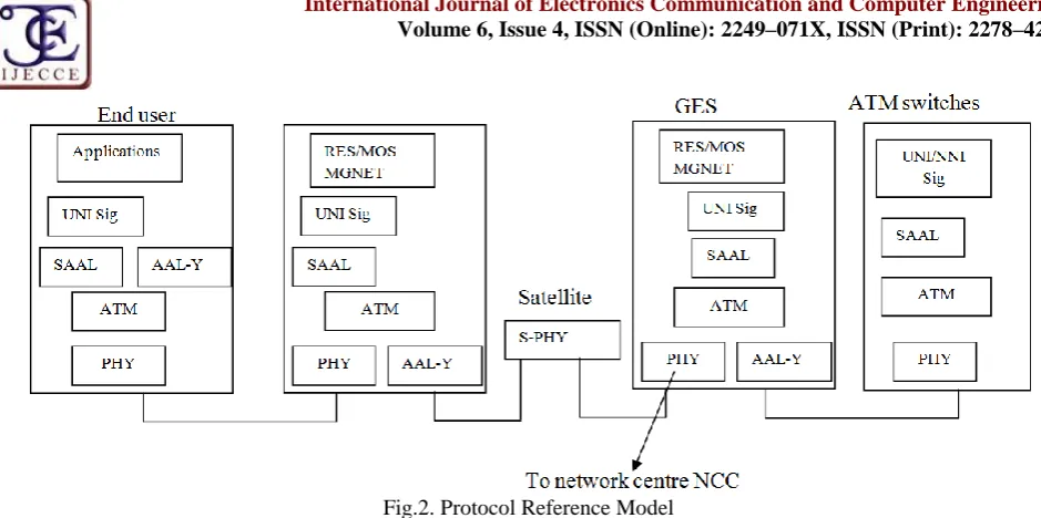
2.3.3 The protocol reference model
The protocol reference models for fixed ATM network access and network interconnection are shown in figure 2 below. In order to support ATM onboard LCS satellites, the communication subsystem must implement ATM’s user-network interface UNI and private network to-network interface (PNNI) protocol [12], where UNI is a signaling protocol for connecting end users, and PNNI is a routing as well as a signaling proocol for connecting ATM switches.
The PNNI routing protocol extends IP’s link state protocol [12] to add resource information such as the maximum and available link-bandwidth, the switch buffer resources, guaranteed delay and delay variations, etc. In this architecture, it is assumed that the mobility of the UT and GES are centralized at the NCC.
Copyright © 2015 IJECCE, All right reserved Fig.2. Protocol Reference Model
III.
S
YSTEMA
NALYSIS OFT
ERRESTRIALN
ETWORKSIn section 2.0 above, we analyzed and presented ATM solution for the LCS LEO constellation to complement the terrestrial infrastructure. The current trend is to use the ATM technology as the underlying infrastructure for the next generation of enterprise and global IP networks [8A]. Future data communications system will integrate satellite and terrestrial networks. The focal point of the integration is to provide complete global coverage, enabling mobile users to roam globally. We discuss the analysis .of five representatives of the terrestrial networks as follows:, 3G networks in section 3.1, Mobile Internet in 3.2, the Public Switched Telephone Network (PSTN) in 3.3 , the Cable Television Networks (CATVN) in 3.4, and finally the Personal Communications Services (PCS) Cellular in 3.5.
3.1 3G Networks
3G is a term [36] that covers all new high speed packet oriented wireless network standards that are supposed to replace the digital second generation networks. 3G architecture provides the building blocks for Enhanced Data Rates for Global Evolution (EDGE) which in essence bumps data rates up to 384Kbps; The General Packet Radio Services (GPRS) will enable GSM networks to transfer data service and wireless contents over the networks at 115Kbps; while CDMA competitors will migrate to cdma2000. Cdma2000 enable providers to use existing hard wares to initially migrate to 3G1x,providing data rates of 144 Kbps and doubling the voice capacity of the network and later migrate to 3G1x EV with data rates capable of 2.4 Mbps. The other technology for migration is the wide band CDMA.
In WCDMA, voice, images, data and video are first converted to a narrow band digital radio signal. WCDMA uses variable-rate the vast development of next generation mobile networks that include systems like CDMA2000, W-CDMA, GPRS, EDGE, GSM and UMTS. Competing companies worldwide are migrating to 3G wireless as fast as possible in various steps: In Europe, GSM will migrate to universal mobile telecommunication system (UMTS) using techniques in digital processing and can achieve
multi-rate transmission. WCDMA has been adopted as a standard by the ITU under the name IMT-2000 direct sequence spread spectrum (DSSS). This is the technology in use by NTT DoCoMO in the Japanese market. we discuss the followings; GSM, GPRS,WCDMA and UMTS networks in details as follows: GPRS,WCDMA and UMTS networks in details as
3.1.1 GSM:
The success of mobile terminals has created a tremendous need to access messaging and streaming services wirelessly as well as voice data in a mobile fashion [13]. The most widely deployed standard for mobile radio networks is the GSM. GSM system is a Frequency-and Time-division system; eeach physical channel is characterized by a carrier frequency and a time slot number. GSM system frequencies include two bands at 900MHz and 1800 MHz commonly referred to as GSM-900 and DCS-1800 systems.ETSI originally defined GSM as a European digital cellular telephony standard. GSM interface defined by ETSI laid the groundwork for a multivendor network approach to digital mobile communication.
Figure 3 below shows a GSM public land mobile network (PLMN).
A major importance of GSM is its potential for for delivering enhanced services requiring multimedia: Voice, image, and data [16]. The key to delivering enhanced services is SS7, a robust set of protocol layers designed to provide fast, efficient, reliable transfer and delivery of signaling information across the signaling network and support both the Switched Voice and Non-voice applications. Fig 3 below shows the GSM subsystem entities and their logical interconnections as follows:
The MS consists of the physical equipment used by the
subscriber to access a PLMN for offered
telecommunication service.
Copyright © 2015 IJECCE, All right reserved with the user and the air-interface to the BSS; the
subscriber identity module (SIM) that is a Smart Card issued at the subscription time identifying the user’s
personal information (IMSI, TMSI, LAI, among others).This can effectively be considered a sort of logical terminal.
Fig.3. GSM Public Land Mobile Network (PLMN)
LEGENDS:
MS: Mobile StationBSS: Base Station Subsystem BTS: Base Transceiver Station BSC: Base Station Controller
MSC: Mobile Service Switching Centre MS: Mobile Station
BSS: Base Station Subsystem BTS: Base Transceiver Station BSC: Base Station Controller
MSC: Mobile Service Switching Centre
MAP/I: carries encapsulated messages between the mobile equipment and HLR interface protocols.
MAP/B: MSC to VLR (if the VLR is located outside the MSC).
MAP/C: Interrogation of the HLR by the GMSC. MAP/E: MSC to MSC for Inter-MSC handovers.
MAP/D: MSC/VLR to HLR mainly for mobility management and also to provide call-related information for incoming calls.
The BSS. This is the physical equipment that provides radio coverage to prescribed geographical areas, known as the cells. It contains equipment required to communicate with the BS. Functionally, a BSS consists of a transmitting function performed by the BTS. The BTS is the radio transmission equipment and covers each cell. It is the counterpart of the MS for physical communication over the air-interface.
The BTS components include a transmitter, a receiver, and signaling equipment to operate over the air-interface, and are physically located in the centre of the cells where the BSS antenna is installed. A BSS can serve several cells because it can have multiple BTSs. The BSS communicates with the user through the wireless air-interface and with the wired infrastructure through the wired protocols. Data transmission protocols over the air-interface are different from that of the wired infrastructure. As a result, the BSS provides for the translation among these protocols. To implement GPRS packet data
services on the same air interface as GSM, the BSS also separates packet switching data from the PSTN traffic and directs it to the packet switched data networks. The second architectural element of the BSS is the BSC, that is, a small switch inside a BSS in charge of control function carried out by the BSC (i.e., frequency administration and handover among the BTS inside a BSS).
Copyright © 2015 IJECCE, All right reserved current location, forwarding address, authentication/
ciphering keys, and billing information as well as the ISDN telephone number for the terminal; (iii) The VLR: This is the functional unit that dynamically stores subscriber information when the subscriber is located in the area covered by the VLR. Maintenance of two databases at home and at the visiting site allows a mechanism to support call routing and dialing in a roaming situation where the MS is visiting the coverage area of a different MSC.
GSM Interfaces and Protocol Architecture
(MS to BTS) The Radio Interface
The interface between the MS and the BTS is the Um radio interface. The physical interface comprises a set of physical channels accessible through FDMA and TDMA. Each physical channel supports a number of logical channels used for user traffic and signaling. The radio interface uses the Link Access Protocol on Dm channel (LAP Dm). This protocol is based on the principles of the ISDN Link Access Protocol on the D channel (LAP D) protocol.
The Radio resource layer manages the dialog between the MS and the BSS concerning the management of the radio connection including connection establishment, control, release, and changes (e.g. during handover). The mobility management layer deals with supporting functions of location update, authentication, and encryption management in a mobile environment. In the connection management layer, the cell control entity controls end-to-end call establishment and management.
The A
bisInterface (BTS to BSC)
The interconnection between the BTS and the BSC is through a standard interface, Abis. The primary functions carried over this interface are traffic channel transmission, terrestrial channel management, and radio channel management. Two types of communications links: traffic channels at 64Kbps carrying speech or user data for full or
half-rate radio traffic channel and signaling channels at 16kbps carrying information for BSC-BTS and BSC-MSC signaling.
The A Interface (BSC to MSC)
The A interface allows interconnection between the BSS radio base subsystem and the MSC. The physical layer of the A interface is a 2Mbps standard Consultative Committee on Telephone and Telegraph (CCITT) digital connection. The signaling transport uses Message Transfer Part (MTP) and Signaling Connection Control Part (SCCP) of SS-7. At the interface between BSC and MSC, the lower layers are realized by the MTP of SS7. The SCCP offers the necessary signaling functions required to provide services such as setting mobile facilities for voice and non-voice applications in a mobile network. The Base Subsystem Application Part (BSSAP) serves primarily as a bridge between the radio resource (RR) management and the MSC, handling for instance the assignment and switching at call setup and handover processing. It therefore provides the functionality typically provided by the transport layer, application layer, and network management of OSI.
The MSC is connected to the signaling network of SS7 and is responsible for exchange of all information required for call setup, maintenance and management Transaction capability application part (TCAP) contains functions to provide associations between two TCAP users as well as protocols and services to perform remote operations. It, therefore, provides functionality of the OSI transport layer. The call-related signaling between MSCs and external networks uses the ISDN user part (ISUP), while all GSM-specific signaling between MSC and location registers is performed via the mobile application part (MAP).
The GSM protocol architecture for signaling and mapping onto the corresponding OSI layers is shown in Fig 4 below.
Fig4.The GSM protocol architecture.
LEGENDS:
RR = Radio ResourcesBSSAP = Base Station Subsystem Application Part MAP = Mobile Application Part
SCCP = Signaling Connection Control Part CM = Communication Management MM = Mobility Management
Copyright © 2015 IJECCE, All right reserved TCAP = Transaction Capabilities Application Part
MTP = Message Transfer Part.
3.1.2 GPRS:
GPRS offers a standard means of providing high speed Internet access that can operate with little or no change to the basic network infrastructure. It uses exactly the same physical radio channels as GSM. However, GPRS is an enhancement of the GSM. It extends the packet capabilities of GSM network to higher packet data rates and packet messages as well as provide a packet switched bearer in GSM network. The GPRS Technology incorporates two New two new functionality entities into the wireless network infrastructure: Serving GPRS Support Node (SGSN) and Gateway GPRS Support Node (GGSN) as shown in fig 5 below.Fig.5. The basic network architecture of GPRS
The SGSN:
This functions as a delivery node to the network. It serves the mobile station by tracking its location (via HLR) and delivering the data to the base station serving the MS. It controls access to MSS that may be attached to a group of Base Station Controllers (BSCs). This is called the Routing Area (RA) or Service Area (SA) of the SGSN. It is responsible for delivery of packets to the Mobile Switching Centre (MSC) in its Service Area and from the MS to the internet.It also performs the logical link management, authentication and charging functions. SGSN is a router that is similar to the Foreign Agent (FA) in the mobile IP. The interface that connects the MS to the BSS is called the Um interface while the Gb interface connects between the BSS and the SGSN.
The GGSN:
The GGSN acts as a logical interface to the Internet. It maintains routing information related to MS so that it can route packets to the SGSN serving the MS. It analyses the packet data Network (PDN) address of the MS, and converts it to the corresponding Temporary Mobile Subscriber Identity (TMSI) and its equivalent to the Home Agent (HA) in Mobile IP. Gn interface is the interface between SGSN and GGSN GPRS supports IP and X.25 packets at the network layer to be used by end-to-end applications. The GPRS tunneling protocol (GTP) tunnels correspond to the wide a area mobility and a new logical link is created each time the MS makes a handover in the ready state between itself and the SGSN. The handover procedure is very similar to mobile IP. The GTP allows multiprotocol packets to be tunneled through the GPRS backbone. Therefore, GPRS differs from other wireless data technologies standardized for GSM and TDMA systems because it bypasses the circuit- switchedbased voice network and provides direct access to public packet data networks (PPDNs) like the internet [14]. A tunnel identity (TID) is created using a signaling plane that tracks the PDP context of each MS session.
GTP packet is carried by either UDP/IP or TCP/IP, depending on whether the payload is IP or X.25. The GPRS is a low data rate service . The service support s sending point-to-point and point-to-multipoint messages. It provides capacity-on-demand and an always on-data connection, enabling an Internet session to be held continuously with no penalty, since resources are used only when data are being transmitted.
GPRS is a packet radio system. The radio resources are only assigned for the duration of one or a few IP Packets. Therefore, GPRS is embedded in the physical channel, such as FDMA/TDMA, which employs dedicated protocols. The GPRS characteristics are similar to ALOHA systems but it uses queued requests and channel reservation techniques to grow the traffic the the maximum throughput and hold at the maximum.
W-CDMA (Wideband Code Division Multiple
Access):
W-CDMA networks were first proposed by Ericson. It has the following features: It uses DSSS, runs in a 5MHz bandwidth ,interworks with GSM networks ,although it is compatible with GSM and it has the property that a caller can leave a W-CDMA cell and enter a GSM cell without loosing the call.The W-CDMA network system was further pushed higher by the European Union. According to proposals discussed in the context of EST, ITU, and ACTS, the UMTS architecture can be viewed as the union of two approaches. On one hand, one has the access network (AN) point of view, which pictures a GRAN serving a multiplicity of core networks providing all or a subset of UMTS services;. (dual .On one hand, one has the access network (AN) point of view, which pictures a GRAN serving a multiplicity of core networks providing all or a subset of UMTS services; On the other hand, one has the core network point of view , which envisages a network generic enough to be able to handle different kinds of access networks by means of a subdivision of functions into radio dependent and radio-independent domains . The ACTS RAINBOW project approach developed a generic interface between the UMTS Core Network and the radio access parts, providing the ability to connect different (innovative) radio access modules to the same network infrastructure. W-CDMA networks that was considered in the FDD (Frequency Division Duplex) proposal for UMTS [15], provide an inherent flexibility to handle the provision of future 3G mobile multimedia services.
Copyright © 2015 IJECCE, All right reserved may find themselves in. Thus UMTS aims for the
integration of both services and networks [16]. The integration of services to mobile users is identical to services to wireline users and with a comparable equality of services.
Fig.6. Presents the architecture of the UMTS system.
It is composed of the core network(CN) and the UMTS Terrestrial Radio network subsystems (RNS), each including a Radio Network Controller (RNC). Finally, User Equipment (UE) can be connected to one or more Node BSs. The RNC carries out, among others, all the functions that are related with the allocation of radio resources ( Radio Resource Management (RRM) layers, QOS Management) while Node BSs are responsible of physical layer procedures. With UMTS architecture, the RRM entity is responsible for the utilization of the air-interface resources and it covers power control, handover control, admission control, congestion control, and packet scheduling [15].
Whenever a certain service should be provided under certain guarantees ( QOS), a bearer service with clearly defined characteristics and functionality must be set up from the source to the destination of the service, may be including not only the UMTS network but also external networks [15].
The combination of the UMTS and IP-based quality enabled networks seems the right step towards the provision of a quality assured mobile internet.
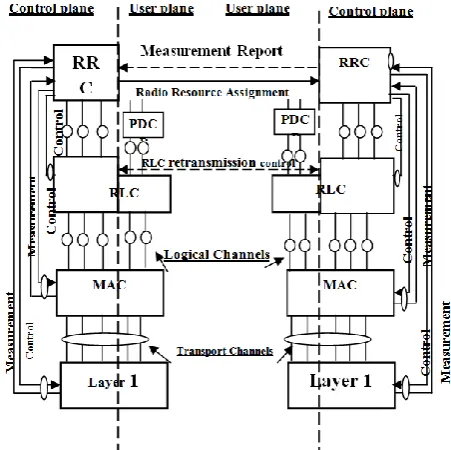
The UTRAN radio Interface protocol stack is shown in fig 7 below.
The radio interface of the UTRAN is layered into three protocol layers: the physical layer (L1), the data link layer (L2) and the network layer (L3). Additionally, the layer 2 is split into two sublayers, the Radio Link Control (RLC) and the Medium Access Control (MAC). On the other hand, the RLC and layer 3 protocols are partitioned in two planes, namely the user plane and the control plane. In the control plane, layer 3 is partitioned into sub-layers where only the lowest sublayer, denoted as Radio Resource Control (RRC) terminates in the UTRAN, as fig 7 shows. Connections between RRC and MAC as well as RRC and LI provide local inter-layer control services and allow the RRC to control the configuration of the lower layers. In the MAC layer, logical channels are mapped to transport channels. A transport channel defines the way how traffic
from logical channels is processed and sent to the physical layer.
Fig.7. The UTRAN radio Interface protocol stack
3.2 Mobile internet
Mobile internet is currently one of the most outstanding trends in computing. Many users depend on the internet for many of their daily routines (business, entertainment, education, family etc) and they wish to extend their connectivity to the times when they are away from their home or office.
Internet consists of individual machines (hosts and routers) and the communication infrastructure that is built up from point-to-point leased lines for a variety of purposes; including router to router LAN traffic and user-to-user ISP traffic. Today’s Internet is built as a giant packet-switched network that offers better bandwidth sharing and is less costly to implement than circuit switching [17].The evolution of the Internet has lead to the convergence of the fixed networks (PSTN, ISDN, Frame Relay, ATM) and mobile networks (GSM, GPRS, UMTS) being converged with the IP as the common transport protocol to deliver end-to-end seamless services with high bandwidth in real-time ,security and QOS[ 4]. In particular, it is starting to acquire properties normally associated with connection oriented service [18].
3. 3.3 The Public Switched Telephone Network
(PSTN)
Telephone networks were originally created to provide voice communications. The entire telephone networks used circuit switching using analog signals to transmit voice; hence it is referred to as an analog system.
With the advent of computer era, the network began to carry data in addition to voice. Then the need to communicate digital data resulted in the invention of the dial-up modem.
Copyright © 2015 IJECCE, All right reserved provides much faster access to the internet through the
telephone network.
We first of all discuss the basic architecture of the telephone network. We then describe the signaling system that makes it more suited to a packet switching network as well as circuit switching network.
The telephone network as shown in fig 8 below is made up of three major components: local loops, the trunks and switching offices.
Fig.8. The basic architecture of the telephone network
1.
Local Loop:
This is an analog twisted pair cable that connects the subscriber telephone to the nearest end office or local central office. The voice bandwidth is 4000Hz (or 4 KHz).2.
The Trunk.
This is digital fibre optics connecting the switching offices. A trunk normally handles hundreds or thousands of connections through multiplexing while transmission is usually through optical fibres or satellites.3.
Switching Office.
A switch connects several local loops or trunks and allows a connection between different Subscribers. Telephone companies have switches located in different switching offices depending on the size of the area of coverage. With an area covered by one area code, one Telephone Company or different independent companies may operate as Local Exchange Carriers (LEC(s)) or end offices. All inter area traffics were handledby inter exchange carriers (IXCs) or toll offices (or Tandem Offices), sometimes called long-distance companies that provide general data communications services including telephone service. The telephone calls going through IXC is normally digitized with carriers using several types of networks to provide service. Another type of switching office called Points Of Presence (POP), is built such that any IXC that wishes to handle calls originating in any area of a particular area code interacts with one another through these POPs. A Subscriber makes connection with another subscriber first through an end switch and then, either directly or through a tandem switch, to a POP. The call now goes from POP of an IXC, passed through the toll office of the IXC, and is carried through the network provided by the IXC.
Signaling System Number 7
As telephone networks entered into a complex network, the functionality of the signaling system increased. The
signaling system was required to perform other tasks [19]. These complex tasks resulted in the tasks of data transfer and signaling transfer being separated in modern telephone networks. Data transfer being done by one network and signaling by another. Fig 9 below shows the situation in which the two networks are separated.
Fig.9.The telephone network signaling system
The data transfer network follows the same type of protocols and models as other networks. This network is for the most part, a Circuit Switched network which can carry multimedia information, although it can also be a packet switched network.
The signaling network is a packet-switched network involving the layers similar to those in the OSI model or internet model. The signaling network has the property that the information needed to convey a telephone address can easily be encapsulated in a packet with all the error control and addressing information and this makes it suited to a packet switching network with different layers [19].
The user or the computer is connected to the Signal Points (SPs). The link between the telephone set and the signal point is common for the two networks. The signaling network uses codes called signaling transport ports that receive and forward signaling messages while the service control points (SCPs) control the whole operations of the network. Other systems such as database centre may be included to provide stored information about the entire signaling network.
Signaling System 7 Protocol Stack
The protocol that is used in the signaling network is called signaling system seven (SS7). It is very similar to the five layer internet model but the layers have different names as shown in fig 10 below.
Copyright © 2015 IJECCE, All right reserved
Physical layer:
MTP LI. The physical layer in SS7 is called message transport part (MTP) level 1. It uses several physical layer specifications such as T-1 (1.544 Mbps) and DCO (64 Kbps).
Data link layer:
MTP level 2. This layer provides typical data link layer services such as packetizing, using source and destination address in the packet header, and CRC for error checking.
Transport layer:
SCCP. This is used for special services such as 800-calling processing.
Upper layers:
TUP, TCAP, ISUP. TUP is responsible for setting up voice calls. It receives the dialed digits and routes the calls. TCAP provides remote calls that let an application program on a computer invoke a procedure on another computer. ISUP can replace TUP to provide services similar to those of an ISDN network.3.4 Cable Television Networks (CATVN)
Cable Television was conceived in the late 1940s as a way to provide better reception to people living in rural or mountainous areas. The system initially consisted of a big antenna on top of a hill to pluck the television signal out of the air, an amplifier, called the head end, to strength it, and a coaxial cable to deliver it to people’s houses.
The generation of cable networks is called a Hybrid Fiber Coaxial (HFC) Network. The network uses a combination of fiber-optic and coaxial cable. The transmission medium from the Cable TV office is a box, called the fiber node, which is an optical fiber. From the fiber node through the neighborhood and into the house is still coaxial. One reason for moving from traditional to hybrid infrastructure is to make the cable network bi-directional.
The Cable TV network started as a video service provider, but it has moved to the business of internet access, and often the telephone business [18, 19].The DSL technology was developed by telephone companies to provide higher data rate connections for residential subscribers over the local loop that uses existing unshielded twisted-pair cable, which is very susceptible to interference, and this imposes an upper limit on the data rate. The cable TV network alternatively uses coax whose theoretical carrying (bandwidth) capacity is hundreds of times more than twisted pair wires [18], but the actual bandwidth available in practice depends heavily on the number of other users currently active and what they are doing.
The Cable TV network started as a video service provider, but it has moved to the business of internet access, and often the telephone business [18, 19].The DSL technology was developed by telephone companies to provide higher data rate connections for residential subscribers over the local loop that uses existing unshielded twisted-pair cable, which is very susceptible to interference, and this imposes an upper limit on the data rate. The cable TV network alternatively uses coax whose theoretical carrying (bandwidth) capacity is hundreds of times more than twisted pair wires [18], but the actual bandwidth available in practice depends heavily on the number of other users currently active and what they are doing.
To use a Cable Network for data transmission, we need two key devices: a cable modem (CM) and a Cable Modem Transmission System (CMTS) as shown fig 11 below.
(a) Cable Modem Transmission System (CMTS)
(b) Cable modem (CM)
Fig.11. The Cable TV network (a) Cable Modem Transmission System (CMTS) (b) a cable modem (CM)
The cable modem transmission system (CMTS) is installed inside the distribution hub by the cable company. It receives data from the internet and passes them to the combiner, which sends them to the subscriber. The CMTS also receives data from the subscriber and passes them to the internet as shown in fig 11(a) above.
Several standards have been created for data transmission over the HFC network but the prevalent one is the one devised by the multimedia Cable Network Systems, called Data over cable system interface specification (DOCSIS). This defines all the protocols necessary transport data from CMTS to CM.
3.5 Personal Communications Services (PCS)
Cellular
Recently, mobile applications are becoming very important. Internet-based applications such as internet access, m-commerce, multimedia email, tele- medicine, mobile Geo-position are being adapted to the cellular systems. Examples of personal communications services are WAP and i-mode among others.
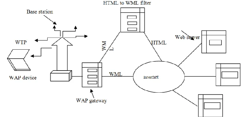
Copyright © 2015 IJECCE, All right reserved Fig.12. The reference architecture
WAP introduces a gateway in between the wireless client and the rest of the internet which manages the delivery of content to the mobile terminal. The gateway acts as a proxy device within the network while the micro browser in the handset coordinates the user interface and is similar to the usual web browser.
Wireless application environment (WAE)
Wireless session protocol (WSP) HTTP
Wireless transaction protocol (WTP) TLS
Wireless Transport layer security (WTLS)
TCP
Wireless datagram protocol IP
Bearer layer (GSM, CDMA, D-AMPS, GRPS ,etc)
Bearer layer
WAP1.0 PROTOCOL WAP 2.0 PROTOCOL Fig.13. WAP 2.0Protocol Stack
[20] identified the following problems: Lack of resources such as bandwidth, processing power, memory, display sizes, interfaces like keypads, and so on that makes the services expensive. WAP has the following constraints: more latency, less connection stability and predictive availability. Some limitations have also been noted. It provides an extensible and scalable platform for application development for mobile telephones. However, its support on colour terminals is not very good. It does not support seamless roaming between different link level bearer services such as CDPD, GSM. Multimedia communications are not supported very well on WAP. For all these limitations, modifications to WAP will be necessary. It is pertinent to describe briefly the WAP protocol stack as shown below:
The lowest layer supports all existing mobile phone systems, including GSM, D-AMPS, and CDMA. On top of this is the datagram protocol (Wireless Datagram Protocol), which is essentially UDP. Then comes a layer for security, obviously needed in a wireless system. Above
this, is a transaction layer, which manages requests and responses, either reliably or unreliably.
Then comes a session layer, which is similar to HTTP/1.1 but with some restrictions and extensions for optimization purposes. At the top, is a micro browser (WAE).
Modifications to WAP 1.0
WAP technology does not use HTML. Instead, the WAE layer uses a mark-up language called wireless Markup Language (WML), which is an application of (XML) extensible markup language. Thus, a WAP device can only access those pages that have been converted to WML. This greatly restricts the value of WAP. Hence, the architecture calls for an on-the-fly filter from HTML to WML to increase a set of pages available as illustrated in fig 13. WAP 1.0 got things right and they have been continued. First, WAP can be carried on a variety of different networks. Secondly, WAP initially was aimed at supporting a wide variety of devices from mobile phones to powerful notebook computers and still is. Thirdly, first
generation used circuit switched networks, but packed-switched networks were always an option and still are.
Secondly, WAP initially was aimed at supporting a wide variety of devices from mobile phones to powerful notebook computers and still is. Thirdly, first generation
used circuit switched networks, but packed-switched networks were always an option and still are.
The WAP 2.0 also has some new features:
1. Push model as well as pull model. The pull model enables client to ask for a page and gets it while push model supports data arriving without being asked for it. 2. Support for integrating telephony into applications. 3. Multimedia messaging. Along with e-mail and
telephony, multimedia messaging is supported.
4. Inclusion of 264 pictograms. The WAP consortium invented 264 pictograms which includes the following categories: animals, appliances, dress, music, etc. 5. Interface to a storage device. WAP-enabled wireless
Copyright © 2015 IJECCE, All right reserved 6. Support for plug-ins in the browser. Plug-ins can
extend the browser’s capabilities. A scripting language is also provided.
However, various technical differences are also present in WAP 2.0.
First, WAP 2.0 continues to support the old protocol stack as shown in fig 13, but also supports the standard internet stack with TCP and HTTP/1.1 as well. However, four minor (but compatible) changes to TCP were made (to simplify the code): (i) Use of a fixed 64kB window, (ii) No slow start, (iii) A maximum (MTU ) of 1500 bytes, and, (iv) A slightly different retransmission algorithm.
Many initial devices will probably contain both stacks as shown in fig 13.
Secondly, WAP 1.0 is the Markup Language while WAP 2.0 supports XHTML Basic which is intended for small wireless devices such as mobile phones, televisions, PDAs, Vending machines, pagers, cars, game machines, and even watches. XHTML Basic does not support style sheets, scripts, or frames, but most of the standard tags are there.
3.5.2 Information- mode system (i-Mode)
I-mode is the industry standard introduced by Japan’s NTT-DOCOMO in 1999. It is a service that tries to eliminate the use of a gateway and provide access to the internet to the extent possible as shown fig 15 below:
The i-mode system has three major components: a new transmission system, a new handset, and a new language for web page design.
The Transmission System.
The transmission system consists of two separate networks: the existing circuit switched mobile phone network (somewhat comparable to D-AMPS), and new packet switched network constructed specifically for i-mode services. Voice mode uses circuit-switched network and is billed per minute of connection time. The i-mode uses the packet-switched network and are always on (like ADSL or cable), so there is no billing for connection time. Instead, there is a charge for each packet sent. It is not currently possible to use both networks at once [18].
The Handset.
The handsets look like mobile phones, with the addition of a small screen. It is rather a mode of services that are not user-programmable, although they contain the equivalent of a 1995 PC and could probably run on Windows 95 or UNIX [18].The i-mode handsets use the existing circuit-switched network for voice and a new packet-switched network for data. The data network is based on CDMA and transmits 128 byte packets at 9600 bps. Handsets talk Lightweight Transport Protocol (LTP) over the air link to a protocol conversion gateway. The gateway has a wideband fiber-optic connection to the i-mode server, which is connected to all the services. When the user selects a service from the official menu, the request is sent to the i-mode server, which caches most of the pages to improve performance. Requests to sites not on the official menu bypass the i-mode server and go directly through the internet.
The software structure is shown in fig15 below:
Fig.14.The i-mode architecture
Fig.15. The structure of the i-mode software
The bottom layer consists of a simple relative operating system for controlling the hardware. Then comes a module for doing network communication, using NTT DOCOMO’s proprietary LTP protocol. Above, is a simple window manager that handles text and simple graphics (GIF files) with screens having only about 120 x 160 pixels at best. The fourth layer contains web page interpreter (i.e. the browser. I-mode does not use full User interaction module
Plug-ins CHTML
Interpreter
Java
Copyright © 2015 IJECCE, All right reserved HTML, but a subset of it, called compact HTML
(CHTML), based loosely on HTML 1.0. This layer allows helper application like Java and plug-ins, just as PC browsers do. At the top, is a user interaction module, which manages communication with the user.
CHTML is an approximately HTML 1.0, with few omissions and some extensions for use on a mobile handsets. Most of the basic HTML lags are allowed, including <html>, <head>, <title>, <body>, <input>, etc. The <b> and < i > tags are not permitted. The <a> tag is allowed for linking to other pages, but with the addition scheme tcl for dialing telephone numbers.
The CHMTL browser is limited in other ways. It does not support Java script, frames, style sheets, background colours or background images. It also does not support JPED images, because they take too much time to decompress. Java applets are allowed, but are (currently) limited to 10kb due to the slow transmission speed over the air link.
Although NTT DOCOMO removed some HTML tags, it also added some new ones such as the <blink> tag which makes text turn on and off, the align attribute for the <br>tag which helps reduce the danger of words being broken in the middle, <marquee>, which scrolls its contents on the screen as well as the ability to for allowing users to select hyperlinks using the keyboard, clearly an important property on a mouseless computer.
Although the client side is somewhat limited, the i-mode server is a full blown computer, with all the usual features. It supports CGI, PerL, PHP, JSP, ASP, and everything else web servers normally support.
Despite the agreement on the use of XHTML Basic, a threat to WAP and i-mode is lurking in the air: 802.11. The second generation wireless web is supposed to run at 384 kps, far better than the 9, 600 bps of the first generation, but for worse than the 11 mbps or 54 mbps offered by 802.11. Of course, 802.11 is not everywhere but as more businesses open up in cities and rural areas, organizations may decide to install base stations for their employers and customers. There may be enough coverage in urban areas, so people can wander from base station to base station.
In rural areas farmers will probably not install base stations, so coverage will be spotty and limited to the downtown areas of cities, due to limited range of 802.11 (a few meters at best). This may lead to dual-mode wireless devices that use 802.11 if they can pick up a signal and fall back to WAP if they cannot.
i-mode has the following advantages over the WAP services.
The terminal transmits data at 9,600 bps that allows graphics and small text messaging on a larger screen than WAP. This display allows six to seventy lines of text at 16-20 characters per line that can be colour or monochrome.
I-mode can access HTML files across the web using C-HTML without a protocol like WAP.
I-mode is similar to HTM which allows different computers to exchange information.
I-mode extends the HTML to communicate with PDAs and i-mode enabled cellular phones.
Its charging mechanism is based on packet transmission rather than connection time which makes it expensive for most users’ applications.
Section 4: Compares of the satellite and terrestrial
networks
In this section, we compare the various networks that were analyzed in this paper as follows. First, it was stated in [2] that the communications infrastructure of the future will be characterized by the seamless integration of IEO satellite networks with broadband networking techniques in order to support multimedia services and provide global coverage as well as different types of traffics to be heterogeneously distributed to the world population [2].This forms the criteria for our Compares.
4.1: ATM Satellite Network: Its Strengths:
(i) ATM satellite networks met all of the above characteristics and in addition, it has provisions for traffic engineering. Hence, the current trends is to use ATM technology as the underlying infrastructure for the next generation of enterprise and Global IP network,
(ii) It has support for real-time services by adding integrated services and differentiated services QOS models,
(iii)support for integrated services at the edges in the border routers at the gate- way earth stations and within the satellite constellations.
(iv)ATM switching nodes in the sky have mobility enhancement functions.
(v) User terminals have the capability of supporting several different protocols standards including ATM UNI,B-ISDN, Frame-relay TCP/IP among others [11], (vi)The connections between the satellite users and the terrestrial users must be handled by a special ground station known as gateways using Interworking units and also to interconnect the external networks and the ATM satellite networks.
(vii) Non satellite users can be served by terminals that have the satellite adaptation units(SAUs).
Weaknesses:
The overhead of regularly providing routing information of the satellite links in the proposed fully toroidal mesh network geometry is a major obstacle to considering satellite as conventional Internet routers[7].Hence, path-based virtual topology is highly recommended for the standard connection-oriented protocol such as ATM in a highly dynamic but tractable context of satellite constellation.
4.2:IP-Based Satellite Network ,its Weaknesses:
Copyright © 2015 IJECCE, All right reserved information must be updated for both the terrestrial and
satellite networks.
4.3 Mobile Internet: Its Strengths
(i) The Internet uses a giant packet-switched network that offers better bandwidth sharing and is less costly to implement than circuit switching [17].
(ii) The fixed networks (PSTN, ISDN, Frame Relay, ATM) and mobile networks (GSM, GPRS, UMTS) being converged with the IP as the common transport protocol to deliver end-to-end seamless services with high bandwidth in real-time ,security and QOS[ 4].
(iii) In particular, it is starting to acquire properties normally associated with connection oriented service [18].
4.4 GPRS: Its Strengths:
(i) GPRS offers a standard means of providing high speed internet access that can operate with little or no change to the basic network infrastructure
(ii) GPRS supports IP and X.25 packets at the network layer to be used by end-to-end applications.
(iii)The GPRS tunneling protocol (GTP) tunnels supports wide area mobility
(iv)The MS makes a handover in the ready state between itself and the SGSN. The handover procedure is very similar to mobile IP.
(v) The GTP allows multiprotocol packets to be tunneled through the GPRS backbone.
(vi)GPRS differs from other wireless data technologies standardized for GSM and TDMA systems because it bypasses the circuit- switched based voice network and provides direct access to public packet data networks (PPDNs) like the internet [14].
(vii) The service supports sending point-to-point and point-to-multipoint messages.
(viii) It provides capacity-demand and an always on-data connection, enabling an internet session to be held continuously with no penalty, since resources are used only when data are being transmitted.
(ix)GPRS is a packet radio. The characteristics are similar to ALOHA systems but it uses queued requests and channel reservation techniques to grow the traffic to the maximum throughout and hold at the maximum.
Weaknesses:
(i) The GPRS is a low data rate service .
4.5 GSM: Its Strengths
(i) A major importance of GSM is its potential for delivering enhanced services requiring multimedia: Voice, image, and data [16] (ii) The key to delivering enhanced services is signaling system (SS7), a robust set of protocol layers designed to provide fast, efficient, reliable transfer and delivery of signaling information across the signaling network and support both the Switched Voice and Non-voice applications.
4.6 UMTS
Strengths:(i) The users are provided with uniform service access to an integrated existing system of services such as wireline, cordless, cellular, and satellite to mobile and wireline (ii)The integration of services to mobile users is identical to services to wireline users and with a comparable equality of services.
(iii)It is composed by the Core Network (CN) and the UMTS Terrestrial Radio Access Network (UTRAN). The access network (CN) point of view pictures a GRAN serving a multiplicity of Core Networks providing all or a subnet of UMTS services; while the UMTS Terrestrial Radio Access Network (UTRAN). envisages a network generic enough to be able to handle different kinds of access networks by means of a subdivision of functions into radio dependent and radio-independent domains. (iv)The combination of the UMTS and IP-based quality enabled networks seems the right step towards the provision of a quality assured mobile internet.
(v) It envisages a network generic enough to be able to handle different kinds of access networks by means of a subdivision of functions into radio dependent and radio-independent domains.
(vi)The combination of the UMTS and IP-based quality enabled networks seems the right step towards the provision of a quality assured mobile internet.
4.7 W-CDMA Its Strengths:
W-CDMA (Wideband Code Division Multiple Access has the following features:
(i) It uses DSSS, and runs in a 5MHz bandwidth, Interworks with GSM networks, although it is not backward compatible with GSM
(ii) It has the property that a caller can leave a W-CDMA cell and enter a GSM cell without losing the call.
(iii)W-CDMA networks that was considered in the FDD (Frequency Division Duplex) proposal for UMTS [15], provide an inherent flexibility to handle the provision of future 3G mobile multimedia services.
4.8 The Public Switched Telephone Network (PSTN)
Strengths:
Telephone networks were originally created to provide voice communications.; hence it is referred to as an analog system.
(ii The need to communicate digital data resulted in the invention of the dial-up modem to carry data as well as the voice.
Weaknesses
(i) The modem was just too slow, so a new technology, called the digital subscriber line (DSL) that provides much faster access to the internet through the telephone network was developed.
It has a complex network, functionality of the signaling system called signaling system seven (SS7 which .resulted in the complex tasks of data transfer and signaling transfer being separated in modern telephone networks. Data transfer being done by one network and signaling by another [19].
4.9 Cable Television Networks (CATVN), Its
Strengths:
(i) Cable Television was initially conceived as a way to provide better reception to people living in rural or mountainous areas. end, and it usesto strength it, it uses Hybrid Fiber Coaxial (HFC) Network to deliver it to people’s houses.
Copyright © 2015 IJECCE, All right reserved (iii)The Cable TV network started as a video service
provider, but it has moved to the business of internet access, and often the telephone business [18,19].
Weaknesses:
(i) The DSL technology that uses existing unshielded twisted-pair cable, was developed by telephone companies to provide higher data rate connections for residential subscribers over the local loop which is very susceptible to interference, and this imposes an upper limit on the data rate. Alternatively, coax whose theoretical carrying (bandwidth) capacity is hundreds of times more than twisted pair wires can be used, but the actual bandwidth available in practice depends heavily on the number of other users currently active and what they are doing [18].
4.10 Personal Communications Services (PCS)
Cellular
Strengths:
(i) WAP can integrate cellular telephony and the internet by providing web content and advanced services to mobile telephone users.
(ii) The WAP application framework can run several transport frameworks that include SMS, GPRS, IS-136 and Circuit-switched wireless data services among others. (iii)The lowest layer supports all existing mobile phone systems, including GSM, D-AMPS, and CDMA.
(iv) It Supports plug-ins in the browser. Plug-ins can extend the browser’s capabilities.
(v) A scripting language is also provided.
(vi)It provides an extensible and scalable platform for application development for mobile telephones,
(vii) The WAP 2.0 also has some new features: Push model as well as pull model, Support for integrating telephony into applications, Multimedia messaging, Inclusion of 264 pictograms, and Interface to a storage device.
Weaknesses:
(i) [20] identified the following problems: Lack of resources such as bandwidth, processing power, memory, display sizes, interfaces like keypads, and so on that makes the services expensive.
(ii) WAP1.0 has the following constraints: more latency, less connection stability and predictive availability. (iii) Some limitations have also been noted. Its support on colour terminals is not very good.
(iv)It does not support seamless roaming between different link level bearer services such as CDPD, GSM. (v) Multimedia communications are not supported very well on WAP . For all these limitations, modifications to WAP will be necessary.
4.11 Information- mode system (i-Mode)Its Srengths:
It uses two modes:Voice mode and packet-switched mode. Voice mode uses circuit-switched network and is billed per minute of connection time while packet-switched mode uses the packet-packet-switched network and are always on (like ADSL or cable), and it is billed for each packet sent.
The data network is based on CDMA and transmits 128 byte packets at 9600 bps
Java applets are allowed,
It supports CGI, PerL, PHP, JSP, ASP, and everything else web servers normally support.
Weaknesses.
It is rather a mode of services that are not user-programmable, although they contain the equivalent of a 1995 PC and could probably run on Windows 95 or UNIX [Tanenbaum Pg 666].
Current handsets have CPUs that run at about 100 MHz, several megabytes of Flash ROM, perhaps 1MB of RAM, and a small built-in screen. Since there is no mouse, on-screen navigation is done with arrow keys.
The bottom layer consists of a simple relative operating system for controlling the hardware.
A simple window manager that handles text and simple graphics (GIF files) with screens having only about 120 x 160 pixels at best.
I-mode does not use full HTML, but a subset of it, called compact HTML (CHTML), based loosely on HTML 1.0.
CHTML is an approximately HTML 1.0, with few omissions and some extensions for use on a mobile handsets. Most of the basic HTML lags are allowed, but with the addition scheme tcl for dialing telephone numbers.
The CHMTL browser is limited in other ways. It does not support Java script, frames, style sheets, background colours or background images.
It also does not support JPED images, because they take too much time to decompress. but are (currently) limited to 10kb due to the slow transmission speed over the air link.
some HTML tags, like <marquee>, scrolls its contents on the screen as well as the ability to for allowing users to select hyperlinks using the keyboard, clearly an important property on a mouseless computer.
i-mode has the following advantages over the WAP services.
The terminal transmits data at 9,600 bps that allows graphics and small text messaging on a larger screen than WAP. This display allows six to seventy lines of text at 16-20 characters per line that can be colour or monochrome.
I-mode can access HTML files across the web using C-HTML without a protocol like WAP.
I-mode is similar to HTM which allows different computers to exchange information.
I-mode extends the HTML to communicate with PDAs and i-mode enabled cellular phones.
Its charging mechanism is based on packet transmission rather than connection time which makes it expensive for most users’ applications.