Remote Control of the FESTO MPS PA Compact
Workstation for the Development of a Remotely
Accessible Process Control Laboratory
https://doi.org/10.3991/ijoe.v16i05.12809
Saleh A. Ahmad (*)
Higher Colleges of Technology, Dubai, UAE
Shamma K. Alhayyas, Maryam A. Almansoori, Noof A. Almenhali, Fatima S. Alsudain, Afrah H. Alkhaldi
Abu Dhabi Polytechnic, Abu Dhabi, UAE
Abstract—The technical education sector of the UAE adopts hands-on dom-inated curricula with the aim of meeting the industrial needs of highly qualified technical personnel with significant practical experience in their field. The utili-zation of remotely accessible laboratories is one of the technologies that is ex-pected to have a significant role in improving the attainment of hands-on skills. This paper presents the design and implementation of a LabVIEW software in-terface to remotely control the FESTO MPS PA compact workstations. This workstation is commonly used as laboratory equipment and for training in the process-control filed. To showcase the developed remotely accessible process control laboratory, Proportional-Integral-Derivative (PID) and ON/OFF control-lers were designed and implemented on the system. The proposed remotely ac-cessible process control laboratory offers practical and industrial training over the Internet. This feature could open doors for sharing the laboratory's resources between higher educational institutes of the UAE. Which is expected to result in the optimal utilization of the available resources. The proposed remotely acces-sible process control laboratory is expected to have a major cost reduction of the usually high education system cost through the efficient utilization of the availa-ble laboratory equipment.
Keywords—Remotely Accessible Laboratory, Process Control, Education and Training, PID Control, ON/OFF Controller
1
Introduction
offering online training opportunities in the process control area is very limited. An internet-based remote-controlled robot was presented in [14]. This work was a crosso-ver project through an international cooperative program situated in Japan, China, Thai-land, and Taiwan. Williams et al developed a platform that allows remote access to photovoltaic laboratory equipment. Their proposed method enables users to access and remotely control experimental equipment located at Loughborough University [15]. The work in [16] described several advanced solutions for performing laboratory ex-periments over the Internet. These include the use of LabVIEW software and solutions based on the functionalities of modern web browsers. Berntzen et al programmed a PLC to control the operation of the laboratory system and used SCADA to monitor the pro-cess. The web interface was designed using Visual Studio, which allows users to access the lab and collect information about the experiment [17]. An analytical chemistry ex-periment is developed by using a headspace gas-chromatograph (GC) is presented in [20]. Virtual laboratory experimentation has been presented in [21]. A modular Inter-net-based undergraduate laboratory facility using commercially available hardware and software has been presented in [22]. This work feathers a built password control and user tracking, and simultaneously accessibility to multiple clients.
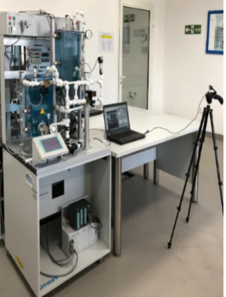
In this paper, LabVIEW software is used to develop a software interface that sup-ports remote access to the process control laboratory at Abu Dhabi Polytechnic; specif-ically, the MPS PA Compact Workstation. The MPS PA Compact Workstation (MPS PA CWS) developed by FESTO Didactic is an educational system that is specially de-signed to meet a number of different industry-oriented training and vocational require-ments. The system represents laboratory-scale equipment that resembles real industrial systems found in different fields including chemical industries, oil refineries, paper, and pulp factories. Furthermore, the MPS PA CWS can be used for training in topics such as programmable logic controllers, closed-loop control design, and fault finding and/or troubleshooting. The MPS PA CWS is shown in Figure 1. This workstation consists of several mechanical components, electrical components, sensors, and actuators. Please refer to the user manual for more information about the CWS [18].
Fig. 1. FESTO MPS PA Compact Workstation.
2
MPS PA CWS System Description
2.1 System components
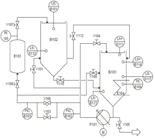
Fig. 2. P &ID for the FESTO MPS compact workstation.
Table 1. MPS PA CWS components description
Labels Description
B101 and B102 B101 and B102 refer to the upper and lower tanks which are storing the liquid. Both tanks have a measurement scale to observe the liquid level
B103 Pressurized air tank
P101 Centrifugal pump
E104 Heating element that is used to increase the liquid temperature in the tank B101
V101, V103, V104, V105, V107, V108, V109, V110, and V112
Manual valves that control the flow rate through the pipes of the MPS PA CWS
V106 2/2 proportional valve for flow control FIC/B102 Flow indicator controller
PIC/B103 Pressure indicator controller ICT/B104 Temperature indicator controller LIC/B101 Liquid-level indicator controller
PI/105 Pressure indicator
2.2 Easyport USB data acquisition card
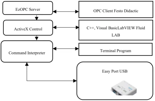
The EasyPort card, developed by Festo, allows bidirectional transmission of signals from sensors and to actuators. The EasyPort is supported by several software packages that are dedicated to the simulation and development of control applications such as Easy Veep, Fluid Lab-PA, and Fluid SIM [19]. The aforementioned software packages do not allow operators to create their own control algorithms. In this work, the commu-nication interface between the PC and the USB EasyPort will be developed based on the ActiveX elements within the LabVIEW programming environment. The EasyPort communicates with the MPS compact workstation by connecting panels dedicated to handling digital and analog signals. Eight digital inputs and outputs of the card are con-nected to the MPS panel by two plug sockets with 24 contacts Syslink according to IEEE 488 standard. While the four analog inputs from sensors and two analog outputs to control the pump and the proportional valve of the MPS compact workstation com-municate to EasyPort by a plug socket with 15-pin Sub D connector. Analog/digital conversion of these signals is performed with a resolution of 12 bits at a sampling fre-quency of 5 kHz [19]. The development of applications with EasyPort can be performed with three different methods as shown in Figure 3. ActiveX controls are used to inter-face with the EasyPort card because they offer accessible methods and events for com-munication with EasyPort modules when LabVIEW is used as a development platform. ActiveX controls are software blocks based on invoke nodes shown in Figure 4. These software blocks can be used by different components of a program to communicate with each other and reuse their code. ActiveX controls are built in COM (Component Model Object) which allows them to be used in other programming languages other than the one in which they were created, among these languages stand out C++, Java, and Visual Basic.
Fig. 3. Easy port software interfaces.
EzOPC Server
ActiveX Control
Command Interpreter
Easy Port USB C++, Visual BasicLabVIEW Fluid
LAB
Fig. 4. Invoke Node.
3
LabVIEW Programming
This section describes the developed Virtual Instrumentations (VIs) used for operat-ing the MPS PA CWS remotely over the Internet. Several LabVIEW VIs were created to manipulate the actuators and obtain information from the sensors of the MPS PA CWS as well as video streaming for the real-time monitoring of the stations.
3.1 Front panel and block diagram design
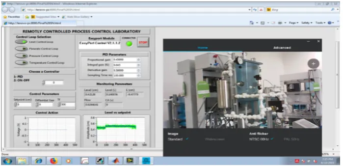
Front panel: The front panel of the designed LabVIEW interface is showing in Fig-ure 5. The user can select the desired control loop from the “Control loop selection” panel with the level being the default option. The controller design is described in Sec-tion 3. The designed panel also allows the user to choose between PID and ON/OFF controllers. The controller selection is achieved by typing-in the number of the desired controller in the “Choose a Controller” panel. The user can also adjust the parameters of the selected controller such as the differential gap, proportional gain, integral gain, derivative gain, and sampling time. As can be seen in Figure 5, the front panel as ac-cessed over the remotely using the Windows Internet Explorer browser. The front panel shows the experimental results on the graphs at the bottom left of Figure 5.
Connect/disconnect to/from EasyPort: The invoke node “Connect’ method of the FESTO ActiveX control is used in order to initiate the login phase. This method checks all serial ports found within the system for EasyPort modules as shown in Figure 6.
Fig. 6. Login to EasyPort.
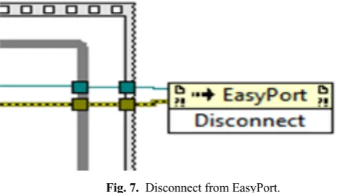
Figure 7 shows the “Disconnect” invoke node method used to accomplish discon-nection from the EasyPort module.
Fig. 7. Disconnect from EasyPort.
Fig. 8. Reading the signal of the level sensor.
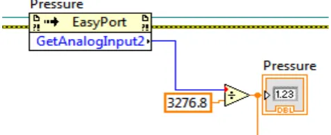
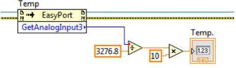
The same invoke node method is used for reading the flow rate, pressure, and tem-perature sensors, by changing the action to GetAnalogInput1, GetAnalogInput2 and GetAnalogInput3 respectively. Figures 9, 10, and 11 shows the LabVIEW diagrams that are used for reading the flow, pressure, and temperature sensors, respectively.
Fig. 9. Block diagram for reading the signal of the flow rate sensor.
Fig. 11. Block diagram for reading the signal of the temperature sensor.
Sending signals to the actuators of the MPS PS CWS: The Invoke Node method with SetAlanogOutpt0 illustrated in Figure 12 is used to set the desired supply voltage for operating the pump. The proportional valve voltage is set in a similar way by chang-ing the method in the Invoke Node to SetAlanogOutpt1, see Figure 13.
Fig. 12. Set the Centrifugal Pump Voltage.
Fig. 13. Set the Proportional Valve Voltage.
3.2 Remote operation
The remote control is accomplished through the web server tool of LabVIEW which allow guests to log in to a local host and remotely operate the MPS PA CWS. The system user can monitor the operations in real time through a camera that is mounted on the system, as shown in Figure 1.
Fig. 14. Explanatory Diagram for the Remote Control and Monitoring of the MPS PA CWS.
Implementation of Web server: The main requirement for the configuration of the web server within LabVIEW VI is to have a functioning online version of the front panel used to control the MPS PA CWS. First, the "Tools" option in the LabVIEW toolbar is selected. Then one has to choose “Options" and finally select "Web Options"; a window opens as displayed in Figure 15. In this window, we proceed to enable the "Enable Remote Panel Server" option and then configure the server communication port. After configuring the server port, “Web Publishing Tool" option is selected, a window will open as shown in Figure 16, where the target VI to be published on the web server is selected.
Fig. 16. Web Publishing Tool Setup.
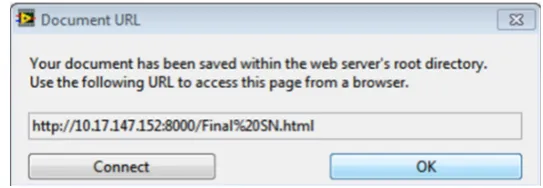
One can also configure the type of interaction between the server and client, enabling or disabling the "Request Control when the connection is established" option. If this option is enabled, the customer must request control of the VI after the connection, otherwise the user takes control of the VI immediately once connected to the server has been established. Finally, the window shown in Figure 17 will appear, this window specifies the address where the file will be saved on the computer that will serve as a server and also the route used to enter the control panel of the plant via the web.
Fig. 17. Web Publishing Tool in LabVIEW URL.
4
System Identification and Control Design
4.1 System identification
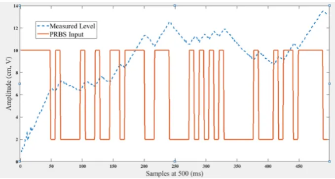
However, only the level control loop system identification is presented here. The cen-trifugal pump was operated on open-loop mode with Pseudorandom Binary Sequence (PRBS) input. The PRBS was chosen because it persistently stimulates the system; i.e. the signal PRBS provide sufficient energy to the process to overcome the noise and disturbances. In addition, the PRBS signal operates between two random fixed limits, and when injected into the process it excites the fast and slow process dynamics. The PRBS is shown in Figure 18.
Fig. 18. PRBS input and the measured level.
Fig. 19. System transfer functions estimation with MATLAB System Identification Tool.
The obtained system model is validated as follows; the validation process starts by dragging the input signal to the box "Validation Data" on the main screen of the system identification tool. Then by selecting “Model Output" which will open the window shown in Figure 20. Figure 21 shows the transfer function estimation report for the best fit and Figure 22 shows the output of the transfer function with the highest confidence level along with the experimental data.
Fig. 21. Transfer function estimation report.
Fig. 22. Real system output vs. the output of the system model with the best fit.
Table 2. Confidence Values Obtained with MATLAB Ident Tool
Step input parameters Percentage
Amplitude (v) Sampling Time (ms) 1 Pole 1 pol, 1 zero 2 poles 2 poles,1 zero 2 poles, 2 ze-ros
2-10 500 91.34% 91.34% 0.9778% -54.41% 92.42%
(1)
4.2 Control design
ON/OFF controller: The ON/OFF controller is a digital controller, which is the simplest form of control. The ON/OFF control action turns the pump ON or OFF based on the level setpoint. The output frequently changes according to actual level readings. To prevent rapid switching of the control action from happening, a level band called hysteresis is created between the ON and OFF operations. The implemented ON/OFF controller is shown in Figure 23.
Fig. 23. ON/OFF controller implementation.
PID controller: The MATLAB Control System Designer Toolbox provides multiple options for the automatic tuning of PID controllers. For example, controllers can be tuned using classical tuning methods, graphically by varying the root locus, or the fre-quency responds. Figure 24 shows the main screen of the Control System Designer Toolbox. The system transfer function obtained in the previous section is imported to the Control System Designer Toolbox and the automatic PID tuning with robust re-sponse time is used to obtain the PID compensator transfer function as shown in Figure 25.
2
2
0.014
3.436
5
1.214
8
0.0004
5.834
9
pG
s
e
s
e
s
s
e
-
+
-
-=
+
-Fig. 24. Control system designer toolbox main window.
The resulted transfer function is given in Equation 2.
(2)
The values of the controller gains are , and . These values were obtained from fine-tuning after implementing the designed gains on the system. The implemented discrete form of the PID controllers is given in Equation 3.
(3) The implemented PID controller in LabVIEW is shown in Figure 26.
Fig. 26. PID controller implementation.
5
Experimental Results and Discussions
The PID and ON/OFF controllers that were designed in the previous sections were implemented on the developed software interface. The experiential results for the ON/OFF controller and the PID controller are presented in this section. The experi-mental result for the ON/OFF controller is shown in Figure 27. The setpoint is 8 cm and the differential gap is set to 2 cm. The ON/OFF controller is operated as follows: the ON/OFF controller is selected by typing number ‘2’ in the “choose a controller” panel. Then, the setpoint and differential gap values can be selected.
The PID controller for the level control system is operated as follows: the PID con-troller is selected by typing number ‘1’ in the “choose a concon-troller” panel. The PID controller parameters are selected and can be tuned online as desired; then, the value of the setpoint is selected. In the provided example, the setpoint was chosen to be 8 cm. The experimental result for the PID controller is depicted in Figure 28. The maximum overshoot is 10% and the settling time is 10 sec.
1.9598e-05 (1+3.5e+04s)
G
=
s
PID 0.45 pk =
k
I=
0.043
k
D=
0.5
1 2
1 1
2
( ) k k k
k k p k k i s k d
s
e e e u u k e e k T e k
T -
--
-æ - + ö
= + - + + ç ÷
Fig. 27. Experimental results for ON/OFF controller.
Fig. 28. Experimental results for PID controller.
6
Conclusion
remote access while viewing the system operations in real time through a camera that is mounted on the system. The proposed remotely accessible process control laboratory can be used to conduct online experiments and /or training to students at other univer-sities in the UAE. In addition, this platform is expected to result in a significant cost reduction and efficient utilization of the available laboratory equipment at IAT.
7
References
[1]H. Wan, K. Liu, J. Lin, and X. Gao, A Web-based Remote FPGA Laboratory for Computer Organization Course. In Proceedings of the 2019 on Great Lakes Symposium on VLSI, New York, NY, USA, 2019; 243-248.https://doi.org/10.1145/3299874.3317999
[2]M. Basso, & G. Bagni, ARTIST, A Real-Time Interactive Simulink-Based Telelab. Proc. IEEE International Symposium on Computer-Aided Control System Design, Taipei, Tai-wan, 2004, 196–201.https://doi.org/10.1109/cacsd.2004.1393875
[3]M. Casini, D. Prattichizzo, & A. Vicino, The automatic control Telelab: A web-based tech-nology for distance learning, IEEE Control System Magazine, 24(3), 2004, 36–44. [4]A. Castellanos, L. Hernandez, I. Santana, & E. Rubio, Platform for Distance Development
of Complex Automatic Control Strategies Using Matlab. International Journal of Engineer-ing Education, 21(5), 2005, 790–797.
[5]M. Corradini, G. Ippoliti, T. Leo, & S. Longhi, An Internet Based Laboratory for Control Education. Proc. IEEE Conference on Decision and Control, Orlando, Florida, 2001, 2833– 2838. https://doi.org/10.1109/cdc.2001.980703
[6]S. Gadzhanov, A. Nafalski, & Z. Nedic, LabVIEW Based Remote Laboratory for Advanced Motion Control. 11th International Conf. on Remote Engineering and Virtual Instrumenta-tion, Porto, Portugal, 2014, 129-136. https://doi.org/10.1109/rev.2014.6784237
[7]D. Hercog, B. Gergic, S. Uran, & K. Jezernik, A DSP-Based Remote-Control Laboratory, IEEE Transactions on Industrial Electronics, 54(6), 2007, 3057–3068. https://doi.org/10. 1109/tie.2007.907009
[8]C. Ko, B. Chen, J. Chen, J. Zhang, & K. Tan, A Web-Based Laboratory on Control of a Two-Degrees-Of-Freedom Helicopter, International Journal of Engineering Education, 21(6), 2005, 1017–1030.
[9]C. Salzmann, D. Gillet, & P. Huguenin, Introduction to Real-Time Control Using Labview With an Applicatann To Distance Learning, International Journal of Engineering Education, 16(3), 2000, 255–272.
[10]J. Sanchez, S. Dormido, R. Pastor, & F. Morilla, A Java/Matlab-Based Environment for Remote Control System Laboratories: Illustrated with an Inverted Pendulum, IEEE Trans-actions on Education, 47(3), 2004, 321–329.https://doi.org/10.1109/te.2004.825525 [11]K. Tan, T. Lee, & F. Leu, Development of a Distant Laboratory Using Labview,
Interna-tional Journal of Engineering Education, 16(3), 2000, 273–282.
[12]S. Oltean, M. Dulău & R. Puskas, Position control of Robotino mobile robot using fuzzy logic. IEEE International Conf. on Automation, Quality and Testing, Robotics (AQTR), Cluj-Napoca, 2010, 1-6.https://doi.org/10.1109/aqtr.2010.5520855
[13]A. Chevalier, C. Copot, C. Ionescu, & R. De Keyser, A Three-Year Feedback Study of a Remote Laboratory Used in Control Engineering Studies, in IEEE Transactions on Educa-tion, 60 (2), May 2017, 127-133.https://doi.org/10.1109/te.2016.2605080
Experiments over the Internet. International Conf. on Engineering Education, Oslo, Norway, 2001.
[17]Z. Aydogmus, & O. Aydogmus, A Web-Based Remote Access Laboratory Using SCADA, IEEE Transactions on Education 52(1), 2009, 126-132. https://doi.org/10.1109/te.2008. 921445
[18]R. Scherer, & H. Kaufmann, MPS PA Compact Workstation Manual and Technical Docu-mentation. FESTO Didactic GmbH & Co. KG, 73770 Denkendorf, Germany, 1st edition, 2008.
[19]S. Ahmad, S. Salman, & A. Abu Ebayyeh, Design and Implementation of Education and Training Graphical User Interface (GUI) Based on NI LabVIEW for the FESTO MPS PA Compact Workstation. International Review of Automatic Control (IREACO), 12. 67, 16441, 2019.https://doi.org/10.15866/ireaco.v12i2.16441
[20]O. Naef, Real Laboratory virtual laboratory or remote laboratory: what is the most effective way, Intl. Journal of Online Engineering, vol. 2, no. 3, 2006.
[21]S. Seiler, Current trends in remote and virtual lab engineering. Where are we in 2013? Intl. Journal of Online Engineering, vol. 9, no. 6, 12–16, 2013.
[22]A. Azad, Delivering a Remote Laboratory Course Within an Undergraduate Program, Int. Journal of Online Engineering, 3, 27-33, 2007.
8
Authors
Saleh Ahmad received his B.Sc. degree in Electronics Engineering from Sebha versity, Libya, in 1999, the M.Sc. degree in Control Engineering from Lakehead Uni-versity, Canada, in 2008, and the Ph.D. degree from Ryerson UniUni-versity, Canada, in 2013. Staring from September 2014 till July 2019, he worked as an Assistant Professor in the Electromechanical Engineering Technology Department, Abu Dhabi Polytech-nic, UAE. He is currently an Assistant Professor in the Mechatronics Technology De-partment, Higher Colleges of Technology, Dubai, UAE His current research interests include harmonic drive modeling, process control, mathematical modeling, and control design for mobile robot manipulators.
Shamma K. Alhayyas, Maryam A. Almansoori, Noof A. Almenhali, Fatima S. Alsudain, and Afrah H. Alkhaldi are senior students with the Electromechanical En-gineering Technology Program (EMET) at Abu Dhabi Polytechnic, Abu Dhabi, UAE.