D. POWELL1, A.E.W. RENNIE1, A. MOLYNEUX2, N. BURNS2 and L. GEEKIE2
1Engineering Department, Lancaster University, Lancaster, UK
2Croft Additive Manufacturing Ltd, Taylor Business Park, Warrington, UK
[email protected], [email protected], [email protected], [email protected],
ABSTRACT
Support structures are essential in additive manufacturing to prevent component deformation. Once removed, the support structures are considered to be scrap, fetching as little as 1% of their value per kilogram when compared to virgin powder. Ball milling has been demonstrated to produce metal powder from machining chips, increasing the value of this scrap. Support structures need to be reduced in size prior to being ball milled, best achieved through slow speed shear shredding. The feasibility of breakdown was analysed by cutting four different types of support structures with a guillotine into small chips. Most chips produced were considered to be too large; however, most support structures reduced in size. It is believed repeated shear forces from shear shredding would continue to break down the support structures into viable feedstock for ball milling. Powder suppliers are identified as the potential adopters for this process, potentially reshaping the additive manufacturing recycling process.
KEYWORDS: Support Structures, Metal Additive Manufacturing, Ball Milling, Shear Shredding
1. INTRODUCTION
Support structures are necessary in all metal components produced by additive manufacturing (AM). Where components have overhanging features or tall, thin parts, support structures are used to hold the component shape as it forms, whilst also providing support against deformation from the sweeping arm [1,2]. Furthermore, supports allow dissipation of residual heat from the melt pool, which would otherwise cause stress and deformation of a component mid-build [1,2,3]. Small support structures are used in virtually all builds to prevent the component being built directly onto the build platform, allowing easy removal of the component [2]. Some processes, such as directed energy deposition, can only deposit material on existing surfaces in previous layers, requiring support structures as a platform to build upon [3]. The support structures are then cut away from the component prior to post-processing.
The number of papers investigating support structures has increased rapidly in recent years [3]. A summary of these papers found that minimising the volume of supports is the typical focus, intending to reduce raw material usage [3]. Other papers investigate how orientation of the component can reduce the number of required supports, but can negatively influence part accuracy and build times [1,3,5]. With much of the academic research within the AM industry aiming to improve the process efficiency, it is surprising that more research has not been undertaken to consider recycling within the industry. Current industry practice is to scrap the unwanted support structures where possible; alternatively they are discarded [3].
A range of metals are used to build with in AM, including Ti6Al4V, Inconel 718, AlSi10Mg SS 316L and SS 304L, varying in cost from £30 to £300 or more per kilogram of virgin powder. It is common for only 1-3% of the cost of one kilogram of virgin powder to be regained per kilogram of uncontaminated scrap metal sold. In the precious metal industry, the value of the gold, silver or platinum “waste” is significantly higher. Support structures are returned to the supplier and swapped, gram for gram, for replacement powder, with an adjustment charge to cover their costs and variations in price. The result is a significantly higher return on investment from the precious metal powder, and the scrap precious metal can be repurposed.
Powder for use in AM has been produced from 304L stainless steel machining chips through ball milling, producing comparable particles to that of water atomised powder [6]. Others have also demonstrated that ball milling can produce powder in other metals, although not for use within AM [7]. Ball milling consumes significantly less energy than atomisation, as it does not require the energy-intense process of melting the metal, making it environmentally preferable to producing virgin powder from remelted support scrap [6]. As metal powder is more valuable than support structures, this paper investigates the feasibility of utilising support structures as a feedstock for ball milling, reducing the carbon footprint of the AM industry whilst providing economic benefit to AM users and powder manufacturers alike.
2. LITERATURE REVIEW
In order to ball mill metal, the typical feed size must not exceed 3mm [8]. Scraps used to produce the metal powder suitable for AM were between 5mm and 20mm in length, although they were typically less than 1mm thick, suggesting that feed size may be larger than recommended maximum values provided by ball mill suppliers [6]. A chip is therefore likely to be “suitably small” for use as ball milling feedstock if it is less than or approximately 1mm wide and thick, provided it is smaller than 20mm in length.
To make support structures viable for ball milling, they need to be broken down into smaller chips. This could be possible using a slow speed shear shredder. Shredding waste metals is not uncommon practice in the production of metal scrap, providing a simple method of breaking apart long chains of support structure. The feasibility of this would vary for different metals depending on their mechanical properties, as the typical 4140 HT steel cutter material may not always be harder than the support structure material [9]. Further to this, many AM users are likely to find shear shredders and ball mills on the market to be too loud for workshop use and too expensive compared with the powder savings.
users at a reduced rate. This would save the AM user money as they get useable, cheaper powder from their low-value scrap, whilst the powder supplier gets money-for-nothing. This would be especially viable with high-value alloys such as Ti6Al4V.
It is worth noting that the size range of particles produced through ball milling would not be suitable for any one powder-based AM process, due to the small particle sizes required [10]. The powder produced may also have an altered chemical composition when compared with virgin powder, as some materials exhibit notable chemical changes between the powder used and the produced component [11]. In order to overcome this issue, the produced powder could be sieved into size fractions and remixed with virgin powder of similar sizes. This could be done by either the AM user or by the powder supplier, with the latter being preferable due to the powder testing facilities available. Previous work has demonstrated the viability of this concept; reused and virgin powder were mixed in several different percentage fractions, finding that the mechanical and chemical properties of produced components were within specification [12]. Frequent analysis and monitoring of this powder would be required to make this feasible.
3. EXPERIMENTAL PROCEDURE
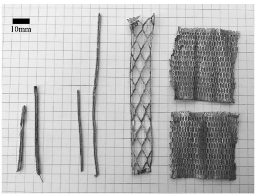
[image:3.595.174.424.469.661.2]Four different designs of support structure were broken down, based on the typical supports used for commercial builds. They are referred to as light border supports, dense border supports, light hatches and dense hatches. These were built using 316L stainless steel powder. Results could therefore be compared to the machining chips used in previous work, due to the near-identical mechanical properties of 316L and 304L stainless steel powders. The supports used were considered to be scrap from commercial builds in a Realizer 250. Figure 1 provides visual representation of these supports. The removal of support structures often causes damage to the supports; as such, the supports are rarely in the pristine condition seen on the build plate.
Figure 1: Supports used for breakdown analysis, overlaid on a 5x5mm grid. From left to right: light hatch, dense hatch, light border support, dense border support
Table 1 gives further information on the uses of each of the support structures that were broken down. It can be assumed that these various supports will always be separated from one another when cut away from the component post-build. As such, there is unlikely to be an event when
a block support (a combination of both borders and hatches) will need to be broken down. This prevents the need to analyse block supports.
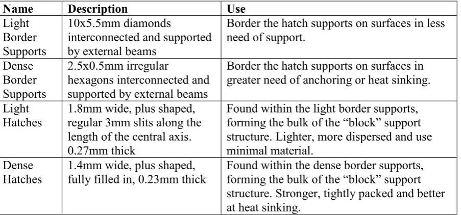
Table 1: A summary of the four support structures used for breakdown analysis
A guillotine was used as a representation of the slow speed shear shredding process, operating similarly to a shredder by using shear force to break down the supports. A Gabro Shear Notcher 3M2 was used to cut strips approximately 4.5mm wide, producing 250g of chips from the various support structures in two hours. These strips were then measured and analysed visually, assessing them for the success of their breakdown and usability in ball milling procedures.
4. RESULTS
Figure 2: Broken down support structures, overlaid on a 5x5mm grid. From left to right: light hatch, dense hatch, light border support, dense border support, variety of small chips from all
support types
Name Description Use
Light Border Supports
10x5.5mm diamonds
interconnected and supported by external beams
Border the hatch supports on surfaces in less need of support.
Dense Border Supports
2.5x0.5mm irregular
hexagons interconnected and supported by external beams
Border the hatch supports on surfaces in greater need of anchoring or heat sinking.
Light
Hatches 1.8mm wide, plus shaped, regular 3mm slits along the length of the central axis. 0.27mm thick
Found within the light border supports, forming the bulk of the “block” support structure. Lighter, more dispersed and use minimal material.
Dense
Hatches 1.4mm wide, plus shaped, fully filled in, 0.23mm thick Found within the dense border supports, forming the bulk of the “block” support structure. Stronger, tightly packed and better at heat sinking.
[image:4.595.76.538.529.693.2]Both light and dense hatches seemed to often bend instead of shearing, as seen in Figure 2. When hatches broke down successfully, small chips were produced, often between 3-10mm. Bent chips and other hatches that were not broken down were, on average, 40mm long.
Similar behaviour was exhibited by light border supports. These supports tended to bend slightly, but typically were able to be broken down into strips between 15-30mm long. Some light border supports were found to fold upon themselves, becoming stronger at these thicker regions. Where this did not occur, these supports were noted to be significantly weaker and easily deformed by hand compared with other supports.
Dense border supports formed strips of consistent size, no wider than 5mm typically, breaking down as expected from the guillotine. They did not bend or deform like other supports, and were found to break apart at various angles to the guillotine. This can be seen in Figure 2, where the supports have evidently been cut in multiple directions to the lattice.
Various small chips and finer particles were also produced, shown in Figure 2. Whilst some of the finest particles were likely to be residual powder from the build process, there is no doubt that small chips, no longer than 5mm, were produced from the guillotine process.
5. DISCUSSION
Hatches did not break down as easily as expected, which is concerning given they are the most common supports. This is most likely due to the ductile nature of 316L Stainless Steel, resisting breakage by deforming plastically. However, this deformation would cause subsequent work hardening of the metal. A second attempt to break it down would likely have more success, indicating that the repeated shear action of shear shredding may be suitable to break these supports down. Different materials used in AM are often brittle, such as Ti6Al4V, and would be unlikely to have this problem with bending [11]. Where they did break down, chips were found to be of a suitably small size. A potential issue could arise with broken down dense hatches, as they have no natural weak points where breakage is likely to occur. This could require notably higher forces from ball milling to break them apart.
Light border supports were unable to be broken down into chips of less than 5mm, thus would be too large for ball milling. However, with these supports being particularly thin and weak, continual shear action is likely to break them down further. When successfully broken down, the thin nature of these supports would make them similar to machining chips, indicating that these would be suitable as a feedstock in ball milling.
The most successful breakdown was observed in the dense border support. The latticed structure ensured the supports had enough strength to resist bending and deformation, whilst providing natural weak breaking points. The breakdown was tested at different angles, as would be the case in shear shredding, and proven to be equally as effective. Combined with the thin nature of these supports, the chips produced would likely be useable as ball milling feedstock.
6. CONCLUSION
It is highly likely that support structures used in AM can be broken down through shear shredding into suitably small chips for use in ball milling. This process would be significantly less energy intensive than the current recycling procedure, especially in metals with high melting points. Demonstrating the viability of this process using 316L Stainless Steel, a highly ductile material, suggests that the other less ductile materials used in AM will yield equally as promising, if not better, results.
However, it is improbable that metal AM manufacturers would have enough support structure waste to warrant investing in equipment such as shear shredders and ball mills, as they would be unlikely to see a return on investment. To see this practice adopted in the AM industry, the onus would fall upon powder suppliers to invest in this equipment, utilising their powder testing facilities to ensure the powder produced is of a suitable quality.
Following these promising results, further research will be carried out on the effects of mixing lower-grade powder with virgin powder on the AM process. Designing and testing a specialised-for-AM shear shredder would be desirable, aiming to reduce both its size and cost, whilst also investigating materials hard enough to break down harder metals than 316L stainless steel. Alternative mechanical breakdown methods, such as hammer milling, should also be investigated and compared to current findings.
REFERENCES
[1] P. Zelinski “Additive’s Idiosyncrasies”, [blog] Additive Manufacturing, 2015. Available at:
https://www.additivemanufacturing.media/blog/post/additives-idiosyncrasies [Accessed 30/01/2019] [2] A. Hussein, L. Hao, C. Yan, R. Everson and P. Young, “Advanced lattice support structures for metal
additive manufacturing” Journal of Materials Processing Technology, 2013, 213 (7), pp. 1019–1026. [3] J. Jiang, X. Xu and J. Stringer, “Support Structures for Additive Manufacturing: A Review,” Journal of
Manufacturing and Materials Processing, 2018, 2 (4), p. 64.
[4] F.T. Piller, R. Poprawe, H.J. Schleifenbaum, G. Schuh, S. Barg, C. Dolle, C. Hinke, M.-H Jank, R. Jiang, W. Meiners, M. Riesener, J. Schrage and S. Ziegler, “Introducing a Holistic Profitability Model for
Additive Manufacturing: An Analysis of Laser-powder Bed Fusion,” 2018 IEEE International Conference
on Industrial Engineering and Engineering Management (IEEM), 2018, pp.1730-1735
[5] G. Strano, L. Hao, R.M. Everson and K.E. Evans, “A new approach to the design and optimisation of
support structures in additive manufacturing,” The International Journal of Advanced Manufacturing Technology, 2012, 66 (9-12), pp. 1247–1254.
[6] B. Fullenwider, P. Kiani, J.M. Schoenung, and K. Ma, “Two-stage ball milling of recycled machining chips
to create an alternative feedstock powder for metal additive manufacturing,” Powder Technology, 2019, 342, pp. 562–571.
[7] J. Liang, M. Jia, X. Guo and D. Zhang “Microstructural evolution and microhardness change of Al–
7wt%Si–0.3wt%Mg alloy granules/powder particles during high energy ball milling,” Materials Science
and Engineering: A, 2014, 590, pp. 307–313.
[8] Tencan, “Horizontal Planetary Ball Mill”, no date, [online]. Available at: http://www.lab-mills.com/planetary/horizontal.html, [Accessed 30/01/2019]
[9] SSI Shredding Systems “M45 two-shaft shredder” no date, [online], Available at:
https://www.ssiworld.com/en/products/two_shaft_shredders/dual_shear_m45 [Accessed 31/01/2019] [10]W.J. Sames, F.A. List, S. Pannala, R.R. Dehoff, S.S. Babu, “The metallurgy and processing science of
metal additive manufacturing”, International Materials Reviews, 2016, 61:5, pp. 315-360
[11]H.P. Tang, M. Qian, N. Liu et al. "Effect of Powder Reuse Times on Additive Manufacturing of
Ti-6Al-4V by Selective Electron Beam Melting” JOM, 2015, 67, pp. 555.
[12]G. Jacob, C.U. Brown, M.A. Donmez, S.S. Watson and J. Slotwinski, “Effects of powder recycling on