http://www.scirp.org/journal/jamp ISSN Online: 2327-4379 ISSN Print: 2327-4352
Foucault Pendulum and Other Coriolis Effects
in Inertial Frames
Pirooz Mohazzabi
Department of Mathematics and Physics, University of Wisconsin-Parkside, Kenosha, WI, USA
Abstract
The purpose of this research is to show that Foaucault pendulum as well as other Coriolis effects, which are normally studied in a rotating coordinate system, can also be analyzed in a fixed reference frame. To this end, Foucault pendulum and other Coriolis effects are studied in inertial reference frames. The approach is simple, yet rigorous, and the results are exactly the same as those obtained in non-inertial reference frames but without resorting to some of the assumptions that are needed in rotating coordinate systems.
Keywords
Foucault, Pendulum, Coriolis, Inertial, Non-Inertial, Frame
1. Introduction
One of the fascinating devices exhibited in many science museums around the world is Foucault pendulum. The pendulum was invented in 1851 by French physicist Jean-Bernard-Lon Foucault (1819-1868), who was educated for medical profession but his interests turned to experimental physics [1]. Foucault devised his pendulum to provide an experimental proof for the rotation of Earth about its axis. His original pendulum consisted of a 28-kg iron ball suspended from the dome of Panthéon in Paris by a steel wire 67 m long.
The pendulum, which has an effectively twist-free suspension, consists of a heavy bob attached to a very long string, several stories tall. The bob essentially oscillates in a horizontal plane, executing a simple harmonic motion relative to the fixed stars. However, as a result of the rotation of Earth about its axis, the os-cillations of the bob exhibit a precession which is clockwise in the Northern Hemisphere and counterclockwise in the Southern Hemisphere.
Although Foucault pendulum is briefly mentioned in some introductory physics books [2] [3] [4], its rigorous quantitative treatment is not presented un-How to cite this paper: Mohazzabi, P.
(2017) Foucault Pendulum and Other Co-riolis Effects in Inertial Frames. Journal of Applied Mathematics and Physics, 5, 1016- 1026.
https://doi.org/10.4236/jamp.2017.55089 Received: March 24, 2017
Accepted: May 12, 2017 Published: May 16, 2017
Copyright © 2017 by author and Scientific Research Publishing Inc. This work is licensed under the Creative Commons Attribution International License (CC BY 4.0).
til the concept of Coriolis force in a rotating coordinate system is introduced in more advanced courses in classical mechanics [5] [6] [7] [8]. This treatment is elegant and quite sound. However, in principle any phenomenon that can be described in a non-inertial coordinate system can also be described in an inertial system, and Foucault pendulum is no exception.
In this article, after a brief description of Foucault pendulum as well as other Coriolis effects in a rotating coordinate system, a simple yet rigorous description of these effects in an inertial system is presented.
2. Coriolis Effects in Rotating Reference Frames
In this section we give a brief review of Foucault pendulum and lateral deflec-tions of a projectile near the surface of Earth as observed by an observer in a coordinate system attached to the Earth’s surface.
2.1. The Foucault Pendulum
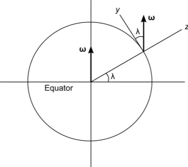
Consider an experiment site on the surface of Earth at latitude λ where a Foucault pendulum is located. Figure 1 shows the cross-section of Earth con-sisting of the great circle that passes through this point and the north and south poles. The xyz system is attached to the surface of Earth and rotates with it, with its origin at the equilibrium point of the bob of the Foucault pendulum. The z
axis is perpendicular to the surface of Earth, while the y axis points to the north and the x axis (not shown) is eastward (into the page). In this coordinate system, the angular velocity of the spinning Earth
ω
has components0
cos
sin
x y z
ω
ω ω λ
ω ω λ
=
=
=
(1)
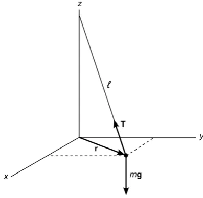
[image:2.595.277.468.533.702.2]The traditional treatment of the Foucault pendulum begins by considering the differential equation of motion of the pendulum in this xyz non-inertial coordi-nate system [7],
2
mr=mg+ −T mω×r (2) where g is the acceleration due to gravity at the surface of Earth, T is the string tension, and r is the position vector of the bob of the pendulum. The first approximation in this treatment is that the centrifugal force −mω×
(
ω×r)
, being of the order of ω2, is negligibly small compared to the other terms and, therefore, is not included.Figure 2 shows the same coordinate system described in Figure 1 but from a different perspective. Decomposing Equation (2) into its x, y, and z components, and using Equation (1), we obtain
(
)
2 cos sin
2 sin
x
mx T m z y
l y
my T m x
l
ω λ λ
ω λ
= − − −
= − −
(3)
The z equation does not appear in (3) because the second approximation in this treatment is that the bob of the pendulum remains in the xy plane and, therefore, the z coordinate and all its time derivatives vanish. Finally, it is as-sumed that the amplitude of the oscillations is small enough so that the tension in the string is approximately equal to mg. Therefore, Equations (3) reduce to
2
2
z
z g
x x y
l g
y y x
l
ω
ω = − +
= − −
(4)
where ωz =ωsinλ is the vertical component of the Earth’s angular velocity. By choosing a second coordinate system x y z′ ′ ′, , that rotates about the z axis with an angular velocity −ωz, the above two coupled differential equations trans-
[image:3.595.272.471.495.689.2]form into
( )
( )
cos z sin z 0
g g
x x t y y t
l ω l ω
′+ ′ + ′+ ′ =
(5)
and an identical equation, except that the sine and cosine are reversed. These equations can be satisfied at all times only if the coefficients of sine and cosine are identically zero, i.e.,
0 0 g x x l g y y l ′+ ′= ′+ ′=
(6)
which describe a two-dimensional harmonic oscillator in the x y′ ′ plane. This
oscillator, therefore, precesses relative to the unprimed system about its z axis with an angular velocity ωz =ωsinλ, clockwise in the Northern Hemisphere and counterclockwise in the Southern Hemisphere.
2.2. Lateral Deflections of a Projectile Near the Earth’s Surface
Motion of a projectile near the surface of Earth from the standpoint of a rotating coordinate system attached to the surface of Earth again begins with Equation (2) except that the tension term T is deleted [9]. Thus the x and y components of the equation of motion relative to the coordinate system shown in Figure 2 are still the same as Equations (3) except for the tension terms. A third equation for the z component is now added since the particle is no longer restricted to remain in or near the xy plane,(
)
2 cos sin
2 sin
2 cos
x z y
y x
z g x
ω λ λ
ω λ ω λ = − − = − = − + (7)
These equations can easily be integrated twice to yield
( )
(
)
( )
( )
3 2
0 0 0 0
2
0 0 0
2 2
0 0 0
1
cos cos sin
3
sin 1
cos 2
x t gt t z y x t x
y t x t y t y
z t gt x t z t z
ω λ ω λ λ
ω λ ω λ = − − + + = − + + = − + + + (8)
which describe the position of the particle as a function of time in the non- inertial frame of reference attached to the surface of Earth.
Equations (8) can be used to describe interesting phenomena such as the lat-eral deflections of a horizontally moving projectile. For a bullet or projectile that is fired horizontally with an initial speed v0, Equations (8) give a deflec-tion of 2 0 sin H v ω
δ = λ (9)
These deflections, although small, are of essential importance in long-range ballistics, as well as in explaining large-scale atmospheric phenomena such as cyclonic motions and hurricanes. For example, it is known that hurricanes rotate counterclockwise in the Northern Hemisphere and clockwise in the Southern Hemisphere. To explain this, consider a high-pressure weather system moving into a low-pressure region, as shown in Figure 3. In the Northern Hemisphere, the air is deflected to the right as it moves in and generates a cyclonic motion in the low-pressure region causing a counterclockwise rotation. In the Southern Hemisphere the effect is reversed.
Equations (8) can also be used to describe the lateral deflection of an object falling freely from a height h, by substituting the appropriate initial conditions. The result is
1 2 3
1 8
cos 3
h
x x
g
ω λ
∆ = =
(10)
which is eastward in the Earth’s frame of reference.
Finally, Equations (8) can show that if a bullet is fired straight up from the ground level with an initial speed v0, it will return to the ground west of its starting point by a distance given by
3 0 2 4
cos 3
v x
g
ω
λ
∆ = − (11)
[image:5.595.271.476.516.699.2]Experimental verification of Equations (10) and (11) are very difficult due to the small size of these deflections and the uncertainty in the horizontal compo- nent of the initial velocity of the projectile. For example, suppose that to test the validity of Equation (11), a projectile is fired upward with an initial speed of 50 m/s from the ground level at a latitude of 45˚. Equation (11) predicts a westward deflection of about 8.9 cm for the projectile upon returning to the ground. Now suppose that the direction of the initial velocity is about 0.01˚ off from the
vertical. This causes a lateral deflection of about 8.9 cm, which is equal to the lateral deflection due to the rotation of Earth, making any conclusions regarding the validity of Equation (11) meaningless. Similarly, if an object is released from the top of a building, 100 m tall at a latitude of 45˚, Equation (10) predicts an eastward deflection of about 1.5 cm at the ground level. Now, suppose the object begins its free fall with a horizontal component of velocity of about 5 mm/s due to the vibration of the building and other effects. This causes a horizontal deflec-tion at the ground level of about 2.3 cm, much greater than the lateral deflecdeflec-tion predicted by Equation (10), again making any conclusions impossible [10].
Despite these difficulties, several attempts have been made to measure the lat-eral deflections of a freely falling object. For example, using 948 trials at a lati-tude of 42˚, Hall [11] [12] reported an eastward deflection of about 0.15 cm for an object falling freely from a height of 23 m, which is in reasonable agreement with 0.18 cm predicted by Equation (10). A brief history of the experimental ve-rification of Equation (10), as well as the results obtained and the references thereto are given by Hall [11] and Romer [13].
3. Coriolis Effects in Inertial Reference Frames
We now return to the main objective of this article and show that the above Co-riolis effects can be obtained in an inertial coordinate system using only the components of the Earth’s angular velocity given by Equations (1).
3.1. The Foucault Pendulum
In general when the angular velocity of a rotating object has a component along some axis, it means that the object rotates about that axis with an angular veloc-ity equal to that component. Consequently, according to Equations (1), Earth instantaneously rotates about the z axis with an angular velocity ωsinλ and about the y axis with an angular velocity ωcosλ. We also note that in the Northern Hemisphere where λ >0, the z component of the angular velocity is positive, whereas in the Southern Hemisphere where λ <0, it is negative. This means that if Earth is viewed from the positive direction of the z axis, but in an inertial reference frame, it rotates counterclockwise about the z axis in the Northern Hemisphere, and clockwise in the Southern Hemisphere.
The twist-free Foucault pendulum, because it is not effectively connected to Earth, oscillates in the xy plane, while Earth (and the coordinate system xyz) ro-tates under it with an angular velocity ωz =ωsinλ. Therefore, as observed from Earth, in the Northern Hemisphere the pendulum precesses clockwise and in the Southern Hemisphere it precesses counterclockwise, with a precessional angular velocity ωsinλ. The precessional period of the Foucault pendulum is, thus, given by
Earth 2π
sin sin
T T
ω λ λ
= = (12)
precessional angular velocity has a maximum value of
ω
with a period ofEarth
T .
An interesting feature of this treatment of the Foucault pendulum is that it does not hinge upon any of the approximations made in the rotating coordinate system. Thus, the approximation of the centripetal force being negligible is not needed. Similarly, we do not need to assume that the bob of the pendulum re-mains in a horizontal plane, nor we have to assume that the pendulum is very long. Consequently, the results obtained for the precessional angular velocity and the period of Foucault pendulum are quite general and apply to any pendu-lum of any length. Indeed, it has been shown that the precessional periods for 100-m and 1-m pendula with amplitudes of 1 m are essentially the same [14].
3.2. Lateral Deflections of a Horizontally Moving Projectile
Since any general projectile motion near the Earth’s surface can be viewed as a combination of a horizontal motion and a vertical motion, in this and the fol-lowing sections only these two special cases are discussed.
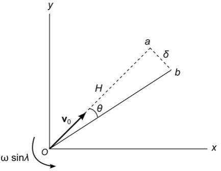
Consider a bullet or projectile that is fired horizontally with an initial velocity
0
v at a point on the surface of Earth at latitude λ, shown in Figure 4. In this figure, the dashed line Oa is the path of the projectile in an inertial frame, whe-reas the solid line Ob is that observed from the xy coordinate system rotating with Earth. While the bullet travels, Earth rotates under it about the z axis with an angular velocity ωsinλ. In a time t, the bullet travels a horizontal distance H, given by
0
H=v t (13)
while the xyz coordinate system attached to Earth rotates about the z axis through an angle
sin t
[image:7.595.267.484.544.712.2]θ ω= λ (14) Therefore, during its horizontal motion and in the Earth’s reference frame, the bullet appears to deflect laterally by a distance
sin
H H t
δ = θ = ω λ (15) where small-angle approximation is used for θ. Elimination of time between Equations (13) and (15) gives
2
0 sin H
v ω
δ = λ (16)
This deflection is to the right in the Northern Hemisphere and to the left in the Southern Hemisphere as observed from the xyz reference frame that rotates with Earth.
3.3. Lateral Deflections of a Vertically Moving Projectile
The lateral deflection of a vertically falling object is somewhat more subtle as it consists of two contributions and that the horizontal component of the accelera-tion due to gravity must be taken into account [15] [16] [17].
Consider a particle that is released from rest at a height h above the Earth’s surface, which is much smaller compared to the radius of Earth, R. Because the particle is initially rotating with Earth, it starts its motion in space with a hori-zontal initial speed that is nearly equal to the speed of the Earth’s surface,
cos
Rω λ, as observed in an inertial reference frame. As the particle continues its
free fall, its horizontal component of motion suffers a backward acceleration due to the horizontal component of the gravitational acceleration, as shown in Fig-ure 5, which is given by
x
g
g x
R
[image:8.595.278.468.471.689.2]= − (17) Therefore, the horizontal or the x-component of motion of the falling particle is
0 g
x x
R
+ =
(18)
with the general solution
( )
sin g cos gx t A t B t
R R
= +
(19)
where A and B are constants. These constants can be determined using the ini-tial conditions,
0 0, 0 cos
x = x =Rω λ (20)
from which we obtain B=0 and A=
ω
R g3 cosλ
. Therefore, Equation (19) reduces to( )
R3cos sin gx t t
g R
ω
λ
=
(21) Furthermore, since in a typical free fall g R t1, we can expand the sine function in the above equation in a Taylor series up to the second term, and ob-tain
( )
3 3 3(
)
(
)
33
1 1
cos cos cos
6 6
R g g
x t t t R t g t
g R R
ω λ ω λ ω λ
= − = −
(22)
The first term on the right side is simply the distance that the surface of Earth has moved horizontally. Therefore the horizontal shift, relative to the Earth’s surface, in the position of the particle in a time t as a result of the retarding component of the gravitational acceleration is
3 1
1
cos 6
x g tω λ
∆ = − (23)
which is a westward shift, as observed from Earth. This is the first contribution to the lateral deflection.
The second contribution comes from the rotation of the coordinate system
xyz, attached to the surface of Earth, while the object is falling. During the time of the fall t and according to Equation (1), this coordinate system rotates about the y axis through the angle
cos t
ϕ ω= λ (24) as shown in Figure 6. Thus, if h is the height that the particle falls during this time, from the Earth-fixed frame an eastward deflection of
2x h tω cosλ
∆ = (25)
is observed, which is the second contribution to the lateral deflection of the fall-ing particle.
The net lateral deflection of the particle during the time of the fall t is the sum of the two contributions,
2
1 2
1
cos 6
x x x gt hωt λ
∆ = ∆ + ∆ = − +
(26)
Figure 6. During the free fall of the particle shown in Figure 5, the xyz coordinate system attached to the surface of Earth rotates about the y axis through an angle ϕ.
2 1 2
h= gt (27) whereby Equation (26) reduces to
3
1 8
cos 3
h x
g
ω λ
∆ = (28)
which is an eastward deflection in the Earth’s frame of reference.
For a particle fired straight up from the ground level, and with the help of di-agrams similar to that shown in Figure 6, it is straightforward to show that the rotation of the xyz coordinate attached to Earth about the y axis causes a west-ward deflection during the rise of the particle followed by an eastwest-ward deflection of equal magnitude during the fall of the particle, resulting in no deflection due to this rotation, i.e., ∆ =2x 0. Therefore, the net lateral deflection of the particle upon returning to the ground is just ∆1x, given by Equation (23). Furthermore, since the total flight time in this case is
0 2v t
g
= (29) we find
3 0 2 4
cos 3
v x
g
ω λ
∆ = − (30)
which is a westward deflection in the Earth’s frame of reference.
Thus the lateral deflections of a horizontally or vertically moving projectile can be obtained not only from the point of view of an observer in a rotating coordinate system in the context of Coriolis force, but also in an inertial refer-ence frame. Equations (28) and (30) can also be derived using conservation of angular momentum of the particle with respect to the center of Earth [10].
4. Conclusion
discussed in the context of an inertial frame that instantaneously coincides with a rotating coordinate system attached to the Earth’s surface. Although this ap-proach is simple, it is rigorous and provides the correct quantitative results that should otherwise be obtained by more advanced techniques in classical mechan-ics. Furthermore, the simple treatment presented here does not require some of the assumptions that are needed in non-inertial reference frames.
References
[1] The New Encyclopedia Britannica (The University of Chicago, Chicago, 1993), 5th Edition, Vol. 4, 900.
[2] Serway, R.A. (1990) Physics for Scientists and Engineers with Modern Physics. 3rd Edition, Saunders, Philadelphia, 324.
[3] Ohanian, H.C. (1989) Physics. 2nd Edition, Norton, New York, 101. [4] Benson, H. (1991) University Physics. Wiley, New York, 112.
[5] Barger, V. and Olsson, M. (1995) Classical Mechanics: A Modern Perspective. 2nd Edition, McGraw-Hill, New York, 241-244.
[6] Marion, J.B. and Thornton, S.T. (1995) Classical Dynamics of Particles and Systems. 4th Edition, Saunders, New York, 398-401.
[7] Fowles, G.R. and Cassiday, G.L. (1999) Analytical Mechanics. 6th Edition, Saunders, New York, 196-198.
[8] Symon, K.E. (1960) Mechanics. 2nd Edition, Addison-Wesley, Reading, 280-283. [9] Fowles, G.R. and Cassiday, G.L. (1999) Analytical Mechanics. 6th Edition, Saunders,
New York, 188-192.
[10] Mohazzabi, P. (1999) Free Fall and Angular Momentum. American Journal of Physics, 67, 1017-1020. https://doi.org/10.1119/1.19163
[11] Hall, E. (1903) Do objects Fall South? Physical Review, 16, 246. [12] French, A.P. (1971) Newtonian Mechanics. Norton, New York, 552.
[13] Romer, R.H. (1983) Foucault, Reich, and the Mines of Freiberg. American Journal of Physics, 51, 683. https://doi.org/10.1119/1.13143
[14] Soga, M. (1978) Precessional Periods of Long and Short Foucault Pendulums. American Journal of Physics, 46, 725-726. https://doi.org/10.1119/1.11276
[15] French, A.P. (1971) Newtonian Mechanics. Norton, New York, 527-528. [16] Renault, J. and Okal, E. (1977) Investigating the Physical Nature of the Coriolis
Ef-fects in the Fixed Frame. American Journal of Physics, 45, 631-633.
https://doi.org/10.1119/1.10780
Submit or recommend next manuscript to SCIRP and we will provide best service for you:
Accepting pre-submission inquiries through Email, Facebook, LinkedIn, Twitter, etc. A wide selection of journals (inclusive of 9 subjects, more than 200 journals)
Providing 24-hour high-quality service User-friendly online submission system Fair and swift peer-review system
Efficient typesetting and proofreading procedure
Display of the result of downloads and visits, as well as the number of cited articles Maximum dissemination of your research work
Submit your manuscript at: http://papersubmission.scirp.org/