DWT BASED IRIS RECOGNITION
MAYURI MEMANE
Sinhgad College of Engineering, Vadgaon (Bk) Pune, Maharashtra, India
SANJAY GANORKAR
Sinhgad College of Engineering, Vadgaon (Bk) Pune, Maharashtra, India
Abstract:
The iris recognition is an emerging technology widely used due to various characteristics such as uniqueness, universal, stable, independent of genetics, acceptable etc. The recognition is carried out using discrete wavelet transform (DWT). It includes collection of iris database, carrying out preprocessing (includes separation of pupil), normalization and feature extraction. Normalization includes polar to rectangular conversion. After this area of interest is selected from which features are extracted using DWT. It generates approximate, horizontal, vertical and diagonal coefficients. These are compared with the stored templates using hamming distance. If the template is match with the stored one than the match ID is displayed. The unauthorized person is indicated by displaying ID equal to ‘00’
Keywords: Biometrics; DWT; Segmentation.
1. Introduction:
In the present world with the advancing technologies, the necessity of security increases. Uptill now we are familiar with the traditional methods such as ID cards, password and secret keys. But these methods have some pitfalls such as ID may be lost, passwords may be forgotten. To overcome these unreliable security systems, the physiological and behavioral characteristics of individuals are used. The physiological characteristic includes iris, retina, fingerprints, palm-prints, hand geometry while behavioral characteristics consist of handwritten signature, voiceprint, gait, gesture, etc. Among these two methods physical biometric has more secure and accurate than the behavioral method [Ezhilarasan (2012)].
1.1 Biological Description:
The iris is a protected internal organ of the eye, located behind the cornea and the aqueous humour, but infront of the lens. A visible property of the iris and the finger print is the random morphogenesis of their minutiae. The phenotypic expression even of two irises with the same genetic genotype has uncorrelated minutiae e.g. twins. Human eye is divided into two chambers. The first one is the anterior chamber and the second one is the posterior chamber, which are separated by iris and lens. The anatomy of the human eye is shown below: [Pospisil (2000)]
Fig. 1. Anatomy of human eye
to black. The most important function of the iris is controlling the size of the pupil. The iris is the colored portion of the eye that surrounds the pupil. It is full of richly textured patterns that are distinct from person to person, and in fact are distinct from left eye to right eye from the same person. Compared with other biometric features such as face and fingerprint, iris patterns are more stable and reliable, and are unrelated to health or the environment. Iris recognition systems are non-invasive to their users, but do require a cooperative subject. For this reason, iris recognition is usually used for verification or identification purposes [Ezhilarasan, et al. (2012)], [Pospisil (2000)], [Ives, et al. (2004)].
2. Methodology:
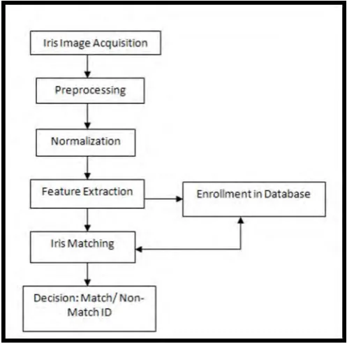
The flow of iris recognition system is shown in Fig. 2. The iris image is applied to the preprocessing block which includes enhancement of image and segmentation. After this the image is normalized by using polar to rectangular conversion. Features are extracted using DWT and match with the stored one using hamming distance. If the template is matching it display the match ID else it display ID equal to ‘00’ i.e. unauthorized person.
Fig. 2. Flow of iris recognition system
2.1 Image Acquisition:
The database consists of different colored iris images captured from net. The image consists of iris and pupil form which pupil is the unwanted part and separated using various preprocessing steps.
2.2 Preprocessing:
2.2.1. Gray Image:
The color image is converted into a shade of gray. That is brightness or luminance of color image is converted into a gray shade by using the formula:
Y 0.3RED 0.59GREEN 0.11Blue (1)
2.2.2 Histogram Equalization:
Histogram equalization is done on each iris image to generate an image whose intensity also covers the entire range of intensity levels. The normalized iris image has very low contrast and it could have a non-uniform brightness in different parts of the image due to the light applied at the acquisition time. This makes the iris texture seem to be with less contrast than it really is. The contrast enhancement of the image is accomplished by means of histogram equalization in order to use the full spectrum of gray levels, hence the textures are highlighted. Further, filtering operation can be applied to remove noisy components [Dhavale (2012)].
N
intensity
max.
.
n
T(x)
x
x
0 i
i
t
Where: ni is the number of pixel at intensity i,
N is the total number of pixel in the image. (0-255)
2.2.3 Segmentation:
The area of pupil and iris is detected and pupil is separated from iris this process is called as segmentation. For this the concept of gradient change is consider. There will be only two important gradients in the region i.e. pupil – iris and iris – sclera, and pupil pixels will be the darkest, iris pixels will be intermediate and sclera pixels will be whiter, this way we can look for the second gradient and take it as iris estimated radius. The left and right boundaries of the iris are found by selecting the largest gradient change to the left and right of the pupil [Annapoorani, et al. (2010)].
The canny edge detector is used as it has zero response to non-edge, response only once to an edge and the difference between actual and detected one is very less. It internally follows certain steps firstly it apply Gaussian filter on the image to remove the noise after this it finds the edges by finding the gradient change in ‘X’ and ‘Y’ direction as follows:
Gaussian Filtering:
S
G
*
I
(3) Compute x and y derivatives:
Ty x T S S S y S x
S
(4)
Compute gradient magnitude and orientation:
2 2
y
x
S
S
S
(5)x y S S 1 tan
After this non-maximum suppression is applied i.e. is suppress the pixel which are not maximum for this it consider the neighboring pixel. The value of current pixel is compared with the two neighboring pixel and if it is greater than the two than it is consider else it is made equal to zero. The value can be compare as follows:
otherwise 0 , , & , , if ,, S x y S x y
y x S y x S y x S y x M (6) After non-maximum suppression hysteresis thresholding is applied which further suppress the pixels which are passed by the non-maximum suppression. This includes following stages:
If the gradient at a pixel is above ‘High’, declare it an ‘edge pixel’ If the gradient at a pixel is below ‘Low’, declare it a ‘non-edge-pixel’
If the gradient at a pixel is between ‘Low’ and ‘High’ then declare it an ‘edge pixel’ if and only if it is connected to an ‘edge pixel’ directly or via pixels between ‘Low’ and ‘ High’
2.2.4Normalization:
cos
r
x
Fig. 3. Polar to rectangular conversion
2
2 y
x r
(7)
Where:
2.3 Feature Extraction:
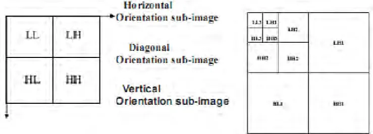
The features are extracted using DWT. It breaks an image into four sub samples. The result consist of one image that has been high pass in the horizontal and vertical directions, one that has been low passed in the horizontal and last that has been low pass filtered in both directions. Where H and L means high pass and low pass filter respectively. While HH means that the high pass filter is applied to signal of both directions, represent diagonal features of the image, HL correspond to horizontal structures. LH results vertical information and LL is used for further processing. It generates approximate, horizontal, vertical and diagonal coefficient which are compared with the stored one [Boles and Boashash (1998)], [Patil and Kulkarni (2009)].
Fig. 4. Three level wavelet transforms
2.4 Hamming Distance:
The template can now be compared with the stored template using Hamming distance (HD) as the measure of closeness. The exclusive-or operator is used to encode the feature vector of any two iris patterns. It detects the disagreement between any corresponding pair of bits. A and B are two iris patterns to be compared, N is the total number of bits. The formula is given below: [Dhavale (2012)], [Patil and Kulkarni (2009)].
Ni
B
A
N
HD
1
1
(9)
3. Results:
Stage 1: The colored iris image is shown in Fig. 5.
Color Image Color Image
Fig. 5. Color image
Stage 2: The above color image is converted into gray shade as follows:
Grayscale Image Grayscale Image
Fig. 6. Gray shade image
Stage 3: The image isenhanced using histogram equalization as shown in Fig. 7.
Enhanced Image Enhanced Image
Fig. 7. Histogram equalization
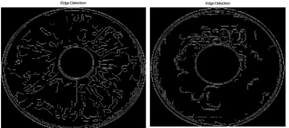
Stage 4: The edges are detected using canny edge detector as shown below:
Edge Detection Edge Detection
Stage 5: The center of image is estimated by tracing for a dark pixel in left and right direction and the center of the image is obtained as follows:
Fig. 9. Start and end point of image
Stage 6: Using the above centre of image the centre of pupil is calculated as displayed in Fig.10.
Fig. 10. Extract centre
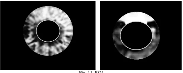
Stage 7: Thearea of interest is selected to eliminate the noise present at the boundary of image.
Fig. 11. ROI
Stage 8: On the above region of interest polar to rectangular conversion is applied as displayed in Fig. 12.
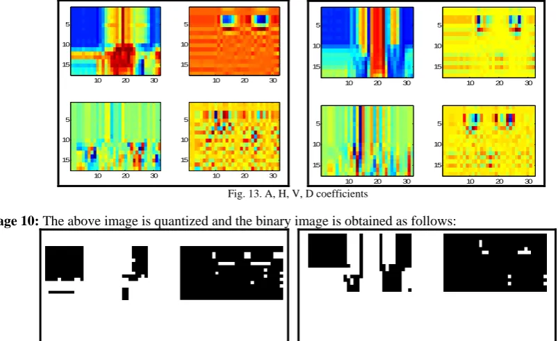
Stage 9: The coefficients are generated using DWT as shown below:
10 20 30 5
10 15
10 20 30 5
10 15
10 20 30 5
10 15
10 20 30 5
10 15
10 20 30 5
10 15
10 20 30 5
10 15
10 20 30 5
10 15
10 20 30 5
10 15
Fig. 13. A, H, V, D coefficients
Stage 10: The above image is quantized and the binary image is obtained as follows:
Fig. 14. A, H, V, D quantized coefficients
Stage 11: The generated coefficients are match with the stored one and the match ID is displayed as shown in equation 10.
Recognized with = 12 Recognized with = 17 (10)
4. Conclusion:
Iris recognition is a relatively new biometric technology which has great advantages such as variability, stability and security, thus it is the most promising for high security environment. The recognition is carried out using DWT. The accuracy is equal to 100% as it displays the correct ID for the entire stored images. The FRR (false rejection ratio) is equal to 0% as it does not reject the image which is present in the database. While FAR (false acceptance ratio) is also equal to 0% as it doe not accept the image which is not present in the database.
References:
[1] Annapoorani, G.; Krishnamoorthi, R.; Jeya, P. G.; and Petchiammal, S. (2010): Accurate and Fast Iris Segmentation, Int. J. of Engineering Science and Technology, 2, pp. 1492-1499.
[2] Boles, W. W. and Boashash, (1998): A Human Identification Technique Using Images of Iris and Wavelet Transform, IEEE Trans on Signal Processing, 46(4), pp. 1185-1188.
[3] Daugman, J. (2004): How iris recognition works, IEEE Trans on Circuits and System for Video Technology, 14 (1), pp. 21-30. [4] Dhavale, S. V. (2012): DWT and DCT based robust iris feature extraction and recognition algorithm for biometric personal
identification, International journal of computer applications, vol. 7, pp. 33-37.
[5] Ezhilarasan, M.; Jacthish, R.; Ganabathy, K.; Subramanian, S.; and Umapathy, R. (2010): Iris Recognition Based on Texture Patterns Int. J. on Computer Science and Engineering, pp. 3071-3074.
[6] http://csjournals.com/IJCSC/PDF2-1/Article_43.pdf. [7] http://en.wikipedia.org/wiki/Histogram_equalization. [8] http://en.wikipedia.org/wiki/Canny_edge_detector. [9] http://www.bobpowell.net/grayscale.htm.
[10] Ives, R. W.; Guidry, A. J.; and Etter, D. M. (2004): Iris Recognition using Histogram Analysis, in Proc. Conf. Rec. 38th Asilomar
Conf. Signal Systems and Computers, pp. 562-566.
[11] Patil, C. M.; and Patilkulkarni, S.; (2009): An approach of iris feature extraction for personal identification, International conference on advance in recent technologies in communication and computing, pp.796-799.
[12] Pospisil, M. J. (2000): The Human Iris Structure and its Usages, Nat. Physica, pp. 87-95.
[13] Shashi Kumar, D. R.; Chhootaray, K. B.; Pattnaik, R. K.; Sabyasachi. (2011): PCA based Iris Recognition using DW. IJCTA, 2 (4), pp. 884-893.
[14] Wildes, R. P. (1997): Iris Recognition: An Emerging Biometric Technology, proceeding of IEEE, 85(9), pp. 1348-1363.
[15] Zhu, Y.; Tan, T.; and Wang, P. Y. (2000): Biometrics personal identification Based on Iris Patterns, 15th International Conference on