Received: June 12, 2002 / Accepted: October 28, 2002
Abstract In this study we tried to develop an analysis pro-gram that can simulate the collapsing process of timber-frame structures under dynamic loading by adopting the extended distinct element method (EDEM). Using the EDEM, it is possible to trace the movement of any parts that were separated from unity after the failure of connect-ing elements, a property that fits our purpose well. As a preliminary study, simple two-story frame structures were modeled and examined by our program. Each model is an assembly of frame members composed of the EDEM ele-ments. The spring elements of the joints have less rigidity than those of the frame members. Several models were analyzed under dynamic loading. The models varied in the configuration of bracing shear walls. Experiments with a one-ninth model were carried out under similar conditions, and the results were compared with the results from nu-merical simulations. Simulated results showed various col-lapsing processes corresponding to the arrangement of the bracing shear wall, and the simulated aspects gave good agreement with the results of the experiments under similar conditions.
Key words Bracing shear wall · Distinct element method · Computer simulation · Timber-frame structure
Introduction
For aseismatic design of wooden structures, it is essential to obtain sufficient knowledge of their vibrational properties.
T. Nakagawa (*) · M. Ohta
Graduate School of Agricultural and Life Sciences, The University of Tokyo, 1-1-1 Yayoi, Bunkyo-ku, Tokyo 113-8657, Japan Tel. 81-3-5481-5253; Fax 81-3-5684-0299
e-mail: [email protected]
Part of this paper was presented at the 50th Annual Meeting of the Japan Wood Research Society, Kyoto, April 2000
Various analyses have been undertaken for this purpose. The characteristic frequency analysis is a well-known, simple method for investigating the vibrational response of wooden structures.1 This method enables us to investigate the vibrational mode and damping properties of structures, but it has some difficulty with the analysis of nonlinear large deformation behavior. The time history response analysis by the shear mass system model,2
the so-called stick-of-dumplings method, can unveil maximum deformation and nonlinear deformation for seismic loading. This method, however, is not sufficiently effective to determine the local deformation and three-dimensional torsion of a whole structure.
These characteristic factors can be clarified in detail using the three-dimensional elastoplastic analysis by the finite element method (FEM)3,4 or by the pseudo-three-dimensional analysis.5,6
Nevertheless, it is difficult for the FEM to simulate the failure of developing processes under dynamic loading. Furthermore, detailed damage informa-tion involving bending deformainforma-tion and fracture aspects (e.g., buckling of a brace, rupture during the bending of columns, rupture of metal connections) of frame structures have hardly been determined by the above-mentioned methods.
To obtain full knowledge of the fracturing behavior of timber structures under seismic loading, it is indispensable to simulate the collapsing process and trace the movement and deformation of each structural member. Collapsing simulations are extremely useful for antiseismic planning of wooden houses because they enable us to make a seismic estimation of each wooden structure with various structural members and reinforcement of virtual spaces. It would also provide extensive economizing by not having to make real size shaking table experiments.
Background of EDEM
The distinct element method (DEM) was originally pro-posed by Cundall7 in 1971 to simulate soils in the domain of civil engineering. With the DEM, a material is considered to be an assembly of circular particles, and there are no resis-tant forces against traction. To give continuity to this dis-crete numerical model, elastic springs and dashpots were added by some Japanese researchers, as shown in Fig. 1.8
This method is called the “modified DEM” or “extended DEM.” The model behaves as a continuous medium while the springs are intact; after the breakage of some of the springs, it enables us to trace the movement of the indi-vidual parts that were separated from each other to destroy the structure’s unity. Using this method, it becomes possible to analyze the fracture-developing processes. One of the authors has applied the EDEM to the simulation of the various fracturing processes of wood and has obtained good results.9–12
Theories
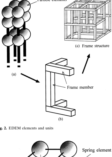
To simulate the collapsing process of three-dimensional wooden-frame structures by EDEM, it is necessary to ex-tend our program to a three-dimensional one. With the EDEM, material is considered to be an assembly of spheri-cal particles spheri-called “particle elements.” Particle elements are connected to each other by elastic springs and dashpots. Between two particle elements, a pairing of a spring and dashpots exists in the normal direction (along the line con-necting the center of the particle elements), and two pairs exist in two shear directions, as shown in Fig. 1. These three pairs of spring and dashpots make up one spring unit, which we hereafter simply call a “spring element.” These spring elements are eliminated when a fracture condition is satis-fied. To save the required memory by the EDEM program, we tried to reduce the number of particle elements by sim-plifying the component. Each member of the wooden struc-ture (i.e., column, sill, beam, brace, metal connector) has four particle elements in its cross section, as shown in Fig. 2a. Figure 3 shows the configuration of the spring
ele-ments connecting eight particle eleele-ments in an elementary unit, where 16 spring elements are equipped in vertical, horizontal, and diagonal directions. The frame element con-sists of elementary units; and by assembling the frame ele-ments, we can obtain a frame structure model (Fig. 2b,c). At the connecting parts of frame members, we placed only four axial spring elements (no diagonal elements).
Equation of motion
The EDEM calculation is performed under the following theoretical concepts: The motion of a spherical particle Fig. 1. Configuration of spring elements of the extended distinct
ele-ment method (EDEM)
Fig. 2. EDEM elements and units
is the displacement vector; and Fi is the angular displace-ment. The time history of ui and Fi can be obtained step by step in the time domain by the numerical integration of these equations. At each step of the calculation the state of the spring elements is checked by the fracture conditions, which are described in the following section. For the EDEM analysis, an element receives forces from all the alive spring elements, and the forces are calculated from the strain of the spring elements. The accelerations of the particle ele-ment in x-, y-, and z-directions are then obtained by the following relations, respectively.
d x dt
Fx m
d y dt
Fy m
d z dt
Fz m
it it it it it it
2 2
2 2
2 2
(3)
The rotatory acceleration is obtained as follows
d dt
M I it it
2 2 F
(4)
where xit, yit, and zit are the displacements in x-, y-, and z-directions on particle element i, respectively; Fxit, Fyit, and Fzit are the components of the force acting on particle ele-ment i; and Mit is the moele-ment acting on it at time t. Velocity increments and displacement increments of the particle ele-ments during a short time period ∆t are obtained by nu-merical integration of these equations. In the DEM or EDEM, the above-mentioned equations of motion are not linked to each other between the different elements, and they are solved as the forward finite difference, which corre-sponds to propagation of the stress wave. Consequently, large total stiffness matrices as in FEM are not required, and calculation amounts are largely saved.13
Following this calculation, we can obtain the three-dimensional coordi-nates of all particle elements consecutively. Thus we can produce every step of the fracturing process in a computer.
Fracture conditions
In the EDEM calculation, the fracture condition is gener-ally defined by the concept of the maximum deformation theory as follows
Dij Lij Lij
(
)
εc (5)where Dij is the distance between particle elements i and j; Lij is the initial distance between them; and εc is a constant.
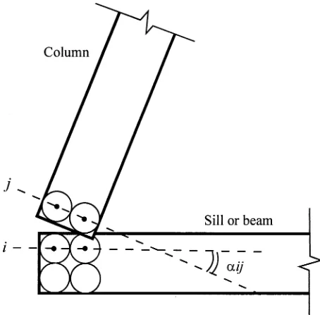
In our frame structure model, as the connecting parts are easily broken by shearing deformation between two frame members, the following equation was added
αij αc (6)
where αij is an angle made between lines i and j correspond-ing to the sill/beam and column, respectively, as shown in Fig. 4; and αc is a fracture angle. If these fracture conditions
are satisfied at any step of the EDEM calculation, four spring elements connecting two particle elements are elimi-nated simultaneously.
Simulations
Simulated model structures
The simulated model frame structures used in our calcula-tions are shown in Fig. 5. The AA structure assumes a wooden frame structure made with 20 frame members (8 beams, 8 columns, 4 sills). The four directions (north, south, west, east) are indicated in the figure for the convenience of Fig. 4. Definition of αij used in the fracture condition
the following explanation. The BA structure has a brace in the northern wall of the first story. This brace is jointed with sill/beam and column. The BB structure has two braces in the northern wall of the first and second stories. In these calculations, the model structures were assumed to be one-ninth scale of the actual size. The sizes of the frame mem-bers are shown in Fig. 5. Cross sections of columns, sills, and beams are 20 20 mm, and those of braces are 10 20 mm. The modulus of spring elements of each frame member was defined to be far larger than that of joint parts. Figure 6 shows the coefficients of the spring elements used here.
Conditions of simulations
Using the above-described model structures, we made our simulations under the following conditions: A mass of 1 kg was added to each beam considering the dead load of the structure. The basement of the model structures (four sills) was moved from east to west at an acceleration rate of 0.3 g (9.8 0.3 m/s2
). The used time period ∆t was 105ms. The dumping coefficient, which has less effect on the calculated results, was set at 1% of the spring constant provisory. The fracture criteria for Eqs. (5) and (6) are determined to correspond to each simulated case. Here we employed 0.5 for εc and p/8 for αc. which gave good results that fitted the
experimental ones.
Materials and methods
Douglas fir (Pseudotsuga menziesii Franco; density 0.45 g/ cm3
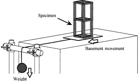
) was used for the frame members. Joints between the frame members were represented by gummed tapes of 2 10 mm. Frame patterns the same as those of the simulated models, shown in Fig. 5, were investigated. The model frame structure was mounted on a sliding basement, which was connected to a 4.2-kg weight by a steel wire (Fig. 7). The dynamic load was applied by dropping this weight
mass. Four 0.25-kg metal weights were mounted on the northern and southern beams of both stories. To prevent lateral shifting of the basement, aluminum guides were set along the runaway. Total collapsing processes were filmed by a high-speed video camera (NAC: HSV-500).
Results and discussion
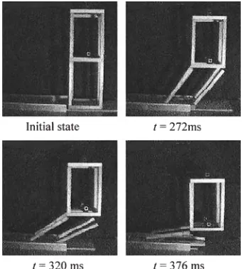
Figure 8 shows the collapsing process of the AA structure, which has no shear wall, obtained by our simulation. Fol-lowing the law of inertia, the movement of the second story delays until that of the basement members. Thus the first-story structure leans gradually; and the spring elements of two joint parts of the upper southwest corner and lower northeast corner disappear at 80 ms, satisfying the angular fracture condition. Then, at 100 ms, six other joint parts of the first story are broken. Finally, all columns of the first story are separated from the beams and sills, and the first story collapses totally, with the second story falling on it. The results of the corresponding experiment are shown in Fig. 9. The results were similar to those of the simulated results.
Equipped with a brace in the northern wall of the first story, the BA structure behaves differently from the AA structure, as shown in Fig. 10. The northern wall of the first story is hardly deformed, whereas its southern wall and the northern wall of the second story are extensively deformed. As the result, the west- and east-side beams lean markedly, and the first breaking of the spring elements occurs at the northern ends of these beams. Then the joints of the col-umns in the southern wall of the first story and northern wall of the second story reach the fracture condition. All the walls except for the northern wall of the first story are broken at 100 ms. Figure 11 shows the experimental results of the BA structure. The total collapsing process coincided well with our EDEM simulation.
Figure 12 shows the collapsing process of the BB struc-ture. In this case, the southern walls of the first and second stories have braces. Both northern walls deform little, whereas the southern wall of the first story deforms markedly. At 70 ms, the west- and east-side beams of the Fig. 6. Modulus of elastic springs
Fig. 8. Collapsing process of the AA structure during the simulation
Fig. 10. Collapsing process of the BA structure during the simulation
Fig. 12. Collapsing process of the BB structure during the simulation
Fig. 9. Collapsing process of the AA structure during the experiment
Fig. 11. Collapsing process of the BA structure during the experiment
first story lean markedly, and the first breaking of the spring elements occurs at the northern ends of these beams. At 100 ms the southern wall of the first story crashes, and con-sequently the southern wall of the second story falls. The northern walls survive these processes. Figure 13 shows the experimental results of the BB structure. In this case, the deformation of the southern walls is similar to the simu-lated results, but there are several differences in the collaps-ing processes between the experimental results and our calculation. Perhaps the estimation of the parameters of the spring elements in our calculation did not match well those of the experimental model.
The total time scale did not coincide for the simulations and experiments, but the simulated result by our method corresponded well with the experimental results qualita-tively. Therefore, it is suggested that the collapsing process of wooden structures with various configurations of shear walls can be predicted by our new method. However, the quantitative outcome is essential for the simulation of actual-size structures, so our calculating method must be improved to realize the quantitative simulations from now on.
Conclusions
The collapsing process of wooden-frame structure models under dynamic loading was investigated by the newly devel-oped numerical program based on the EDEM. Using this method, it was demonstrated that the frame models with different shear wall configurations collapse in different ways. Simulated results corresponded well with the experi-mental results under similar conditions. Our new method proved to be promising for measuring future aseismatic designs, but further improvement is required to realize a quantitative simulation.
Acknowledgments This work was supported in part by a Grant-in-Aid for Scientific Research from the Ministry of Education, Science, Sports, and Culture, Japan (grant 09460072) and by a Grant-in-Aid for Scientific Research from the same Ministry (Research Fellowships of the Japan Society for the Promotion of Science for Young Scientists).
References
1. Nakajima S, Arima T, Nakamura N (1993) Vibrating properties of middle-storied wooden structures. III. Vibrating analysis of full-scale three-storied conventional houses (in Japanese). Mokuzai Gakkaishi 39:917–923
2. Izawa Y, Nakamura T (1997) Dynamic response and earthquake-resistant design of timber structures subjected to strong earth-quake (in Japanese). In: Technical papers of the annual meeting of the Architectural Institute of Japan, C-1, structure III, Tokyo, pp 197–198
3. Sano Y, Umemori H, Ito K, Miyazawa K (2001) A study on three-dimensional elastic-plastic analysis to frame construction. Part 7. Three-dimensional elasto-plastic analysis (in Japanese). In: Sum-maries of the technical papers of the annual meeting of the Archi-tectural Institute of Japan, C-1, structure III, Tokyo, pp 347–348 4. Ming He, Lam F, Foschi RO (2000) Numerical analysis of statically
loaded three-dimensional timber light-frame buildings. In: Proceedings of the 6th world conference on timber engineering, Whistler, 1.2.1.
5. Architectural Institute of Japan (2001) The state of art on new seismic design of timber structures (in Japanese), pp 164–165 6. Sato T, Agawa M, Miyazawa K, Ohara K, Ohashi Y, Koshihara M
(2000) A study on seismic performance of wooden dwelling frame construction with eccentricity. Part 8. Comparison and examina-tion of dynamic analysis and experiment (in Japanese). In: Sum-maries of the technical papers of the annual meeting of the Architectural Institute of Japan, C-1, structure III, Tohoku, pp 299–300
7. Cundall PA (1971) A computer model for simulating progressive, large-scale movements in blocky rock systems. Presented at the symposium of the ISRM, Nancy, pp 129–136
8. Meguro K, Hakuno M (1990) Fracture analyses of concrete struc-tures by the modified distinct element method. Concrete Lib JSCE 16:125–137
9. Ohta M (1998) Fracture process analysis of joints under dynamic loading. In: Proceedings of the 5th world conference on timber engineering, Montreux, vol 1, pp 345–352
10. Ohta M, Kawasaki B (1995) The effect of cutting speed on the surface quality in wood cutting: model experiments and simula-tion by the extended distinct element method. In: Proceedings of the 12th international wood machining seminar, Kyoto, pp 56– 62
11. Ohta M (1996) Fracture process analysis of wood by the extended distinct element method. In: Proceedings of the international wood engineering Conference, New Orleans, vol 4, pp 152–158 12. Sawada T, Ohta M (1997) Simulation of the chip formation in the
orthogonal wood cutting by the extended distinct element method. In: Proceedings of the 12th international wood machining seminar, Vancouver, pp 525–533