140 |
P a g e
VOLUMETRIC ACCURACY ANALYSIS BASED ON
GENERALIZED POSITIONING ERROR MODEL IN
THREE-AXIS CNC MACHINE TOOL
Binit Kumar Jha
1, Mamatha T. G.
2, Neelam Khandelwal
31
Professor & Head in Manufacturing Technology Department, JSSATE, Noida (India)
2
Associate Professor in Manufacturing Technology Department, JSSATE, Noida (India)
3
Assistant Professor in Manufacturing Technology Department, JSSATE, Noida (India)
ABSTRACT
The three-axis machine tools produce an inaccuracy at the tool tip which is caused by kinematics parameter
deviation resulting mainly from manufacturing error and assembly error. Here, all linear axes are theoretically
perpendicular (dot product, cos 90o = 0) to each other and directed along the X, Y, Z coordinate, but in
working machines, the axes are nearly perpendicular (cos 89.9o
0) because of the reasons mentioned above.This kind of error can be taken into consideration only by the precise description of the actual kinematics of the
machine tool. This paper attempts to develop a generalized error model for the effects of positioning errors of
the components of the kinematic chain of a machine in the work space and the results obtained by this model
have been verified experimentally. The mathematical model of the volumetric error, based on positioning error
component, has been derived and the effect of error component on the volumetric accuracy at the cutting point
has been examined. Volumetric error has been studied further for machining a Carrier and an improvement in
quality of Carrier has been obtained by error compensation.
Key Words
:
Kinematics; Positioning Error; Volumetric Error; Error Model; Error Measurement.
I. INTRODUCTION
Errors in position and orientation in multi-axis machine are the result of errors in the individual links of the machine and the interactions between them. Errors originate from the numerous factors such as geometrical errors of the link parameters, thermally induced errors, static and dynamic deflections, kinematic errors related to the relative motion of joints etc.
141 |
P a g e
Therefore, accepting the current technology, it has become necessary to precisely understand the accumulated errors and the effects of error components.
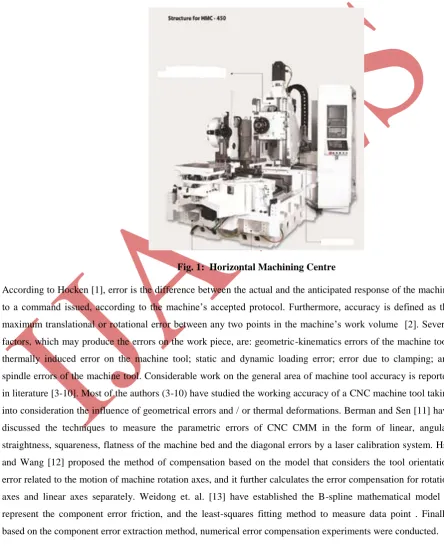
For a three-axis horizontal machining centre (Fig.1), the precision of the cut part is determined by the moving accuracy of an open kinematic chain consisting of three movable slides and one rotational axis. That means, the positioning accuracy at the cutting edge should be defined by the relative moving error between the cutting tool and workpiece . Volumetric error/accuracy represents the overall error/accuracy of a machine tool. Therefore, it has become one of the important indices to represent the quality of such machines.
Fig. 1: Horizontal Machining Centre
According to Hocken [1], error is the difference between the actual and the anticipated response of the machine to a command issued, according to the machine’s accepted protocol. Furthermore, accuracy is defined as the
142 |
P a g e
The objective of the present paper is to develop a generalized positioning error model associated with three axes CNC machine tool as well as to examine the effect of the error component on the volumetric accuracy at the final cutting point . Further, an improvement in the quality has been noticed by compensating the volumetric error of the machine tool in machining a Carrier , used in automobile industries .
II. PARAMETRIC ERROR MODELING FOR THREE-AXIS MACHINING CENTRE
A kinematic model on the basis of the characterization of errors, takes into consideration the deviations in motions and alignment of the structural members of a machine. This coupled with schemes, for tracking changes in model parameter and introducing compensations, forms a comprehensive system for compensating effects of the errors on a machine’s accuracy. The error model developed are discussed in following steps.
2.1 Transformation Model of a Single Joint-link Combination
Links are considered to be rigid body connected either by revolute or prismatic joints. A coordinate frame may be assigned to each link and the relationship between succeeding links may be established using transformations for each of the four variables , namely , d , x , a and t . Using the transformations, nominal relative relationship between adjacent links can be expressed as
Ti-1,i = Tz,d x Tz,x x Tx,a x Tx,t
1 0
0 0
d t
cos t
sin 0
x sin a x cos t sin x cos t cos x sin
x cos a x sin t sin x sin t cos x cos
… (1)
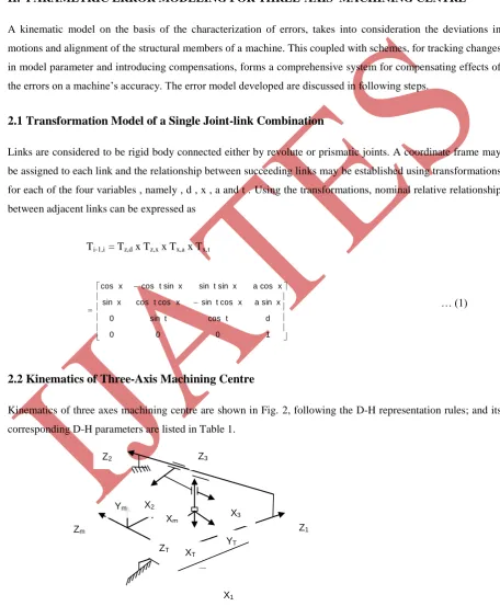
2.2 Kinematics of Three-Axis Machining Centre
Kinematics of three axes machining centre are shown in Fig. 2, following the D-H representation rules; and its corresponding D-H parameters are listed in Table 1.
Fig. 2: Kinematic Diagram of Three – Axis Machine Tool
2
2
T T
Z2
X2
Z3
Z1
X3
Ym
Xm
ZT X T
YT
Zm
143 |
P a g e
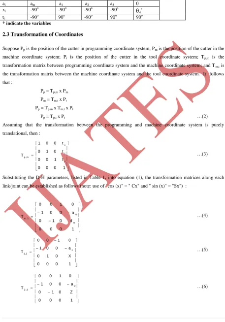
Table 1: D-H Parameters for Three-Axis Machining CentreLink/par. M 1 2 3 4 5
di dm X* Z* Y* 0 L
ai am a1 a2 a3 0
xi -90o -90o -90o -90o
4*ti -90o 90o -90o 90o 90o
* indicate the variables
2.3 Transformation of Coordinates
Suppose Pp is the position of the cutter in programming coordinate system; Pm is the position of the cutter in the
machine coordinate system; Pt is the position of the cutter in the tool coordinate system; Tp,m is the
transformation matrix between programming coordinate system and the machine coordinate system; and Tm,t is
the transformation matrix between the machine coordinate system and the tool coordinate system. It follows that :
Pp = Tp,m x Pm
Pm = Tm,t x Pt
Pp = Tp,m x Tm,t x Pt
Pp = Tp,t x Pt …(2)
Assuming that the transformation between the programming and machine coordinate system is purely translational, then :
1 0 0 0 t 1 0 0 t 0 1 0 t 0 0 1 T y z x m , p …(3)
Substituting the D-H parameters, listed in Table 1, into equation (1), the transformation matrices along each link/joint can be established as follows (note: use of "cos (x)" = " Cx" and " sin (x)" = "Sx") :
1 0 0 0 d 0 1 0 a 0 0 1 0 1 0 0 T m m 1 , m …(4) 1 0 0 0 X 0 1 0 a 0 0 1 0 1 0 0
T1,2 1 …(5)
1 0 0 0 Z 0 1 0 a 0 0 1 0 1 0 0
144 |
P a g e
1 0 0 0 Y 0 1 0 a 0 0 1 0 1 0 0T3,4 3 …(7)
1 0 0 0 0 0 1 0 0 C 0 S 0 S 0 C
T 4 4
4 4 t , 4 …(8)
Tp,4 = Tp,m X Tm,1 X T1,2 X T2,3 X T3,4
Tp,t = Tp,4 X T4,t
1 0 0 0 t Y d a C 0 S t Z a a S 0 C t X a 0 1 0 T y m 1 4 4 z 3 m 4 4 x 2 t , p …(9) and
1 y z x T y z x t t t t , p p p p …(10)when the tool length is 1 unit
0 1 0 0 T j k i y z x t , p p p p …(11)where, [i,k,j]T is the specified direction cosine. By simplifying the above equation, we get
4 4 C S j k …(12)
4 = tan-1(-k/j) …(13)145 |
P a g e
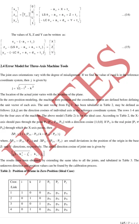
y m 1 4 z 3 m 4 x 2 t , p p p p t Y d a LC t Z a a LS t X a 1 L 0 0 T y z x …(14)The values of X, Z and Y can be written as:
Y Z X ) t d a LC ( y ) t a a LS ( z ) t a ( x y m 1 4 p z 3 m 4 p x 2 p …(15)
2.4 Error Model for Three-Axis Machine Tools
The joint axes orientations vary with the degree of misalignment. If we find the value of i and k in the reference coordinate system, then j is given by
2 2
k i 1
j
The location of the actual joint varies with the location of the plane.
In the zero-position-modeling, the machine zero position and the coordinate system are defined before defining the unit vector of each axis. The unit vector from Fig.2 has been tabulated in Table 2, may be defined as follows: [i,k,j] are the direction cosines of individual axis in the reference coordinate system. The rows 1-4 are for the four axes of the machine. The above model (Table 2) is for the ideal case. According to Table 2, the
X-axis should pass through the point P1 [P1x, P1z, P1y] with a direction cosine [1,0,0]. If P1r is the real point [P1
P1r] through which the X-axis passes, then
P1 = 1 i + (Pz1r – Pz1) k + (Py1r – Py1 ) jwhere,
P1z = (Pz1r - Pz1 ) and
P1y = (Py1r - Py1) are small deviations in the position of the origin in the baseZ- and Y- directions, respectively. The actual direction cosine of joint one is given by
1 1
2
1 2
1 j , k , j
k 1
The results have been obtained, by extending the same idea to all the joints, and tabulated in Table 3. The unknown direction and position values can be found by the calibration process.
Table 2: Position of Frame in Zero Position (Ideal Case)
Coor. /Link
i k J Px Pz Py
1 1 0 0 p1x p1z p1y
2 0 1 0 p2x p2z p2y
3 0 0 1 p3x p3z p3y
146 |
P a g e
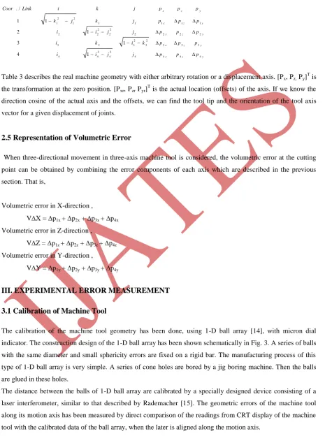
Table 3: Exact Parameters for a Three-Axis Machine Tool for Zero Reference Modely z x y z x y z x y z x y z x p p p j j i i p p p k i k i p p p j j i i p p p j k j k p p p j k i Link Coor 4 4 4 4 2 4 2 4 4 3 3 3 2 3 2 3 3 3 2 2 2 2 2 2 2 2 2 1 1 1 1 1 2 1 2 1 1 4 1 3 1 2 1 1 / .
Table 3 describes the real machine geometry with either arbitrary rotation or a displacement axis. [Px, Pz, Py]T is
the transformation at the zero position. [Pxr, Pzr Pyr]T is the actual location (offsets) of the axis. If we know the
direction cosine of the actual axis and the offsets, we can find the tool tip and the orientation of the tool axis vector for a given displacement of joints.
2.5 Representation of Volumetric Error
When three-directional movement in three-axis machine tool is considered, the volumetric error at the cutting point can be obtained by combining the error components of each axis which are described in the previous section. That is,
Volumetric error in X-direction ,
VX = p1x + p2x + p3x + p4x
Volumetric error in Z-direction ,
VZ = p1z + p2z + p3z + p4z
Volumetric error in Y-direction ,
VY = p1y + p2y + p3y + p4y
III. EXPERIMENTAL ERROR MEASUREMENT
3.1 Calibration of Machine Tool
The calibration of the machine tool geometry has been done, using 1-D ball array [14], with micron dial indicator. The construction design of the 1-D ball array has been shown schematically in Fig. 3. A series of balls with the same diameter and small sphericity errors are fixed on a rigid bar. The manufacturing process of this type of 1-D ball array is very simple. A series of cone holes are bored by a jig boring machine. Then the balls are glued in these holes.
147 |
P a g e
Fig.3: Structure of 1-D Ball Array
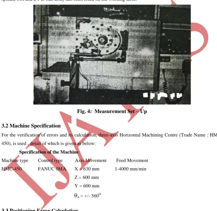
The measuring principle is shown in Fig. 4. The micron dial with magnetic stand has been mounted on the spindle box and a 1-D ball array has been fixed on the working table.
Fig. 4: Measurement Set – Up
3.2 Machine Specification
For the verification of errors and its calculation, three-axis Horizontal Machining Centre (Trade Name : HMC-450), is used , detail of which is given as below:
Specification of the Machine
Machine type Control type Axis Movement Feed Movement HMC-450 FANUC 0MA X = 630 mm 1-4000 mm/min
Z = 600 mm Y = 600 mm
4 = +/- 360O3.3 Positioning Error Calculation
148 |
P a g e
Fig.5: Positioning Error
3.4 Volumetric Error Calculation
As shown in the previous section , the volumetric accuracy is determined according to the translational and
rotational errors of each axis . Namely , the X-direction component of volumetric error (VX) is the sum of
positioning errors p1x , p2x , p3x and p4x . Similarly , the Z- and Y- directional components of volumetric
error (VZ and VY) are the sum of p1z , p2z , p3z and p4z ; and p1y , p2y , p3y and p4y , respectively.
For instance , when the carriage moves 200 , 300 and 400 mm. along the X- , Z- , and Y- axis , respectively , the volumetric error at the cutting point can be obtained step by step as follows :
VX = 0.018 + 0.006 + 0.0 = 0.024 mm.
VZ = 0.007 + 0.023 + 0.0
= 0.03 mm.
VY = 0 + 0 + 0.045 = 0.045 m
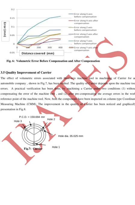
The volumetric errors of the three–axis CNC machine tool for the movement along each axis has been calculated . Then the average error has been calculated and it has been pre-compensated through NC part program. The errors of the machine tool before compensation, and after compensation are graphically presented in Fig. 6.
Distance covered (mm)
E
rr
or (
mm
149 |
P a g e
3.5 Quality Improvement of Carrier
The effect of volumetric errors associated with three-axis machine tool in machining of Carrier for an automobile company , shown in Fig.7, has been studied .The quality of Carrier depends upon the machine tool errors. A practical verification has been done, by machining a Carrier under two conditions (1) without compensating the error of the machine tool , and (2) after pre-compensating the average errors in the work reference point of the machine tool. Now, both the components have been inspected on column type Coordinate Measuring Machine (CMM). The improvement in the quality of Carrier has been noticed and graphically presentation in Fig.8.
Fig.7: Carrier
P.C.D. = 159.694mm Hole 2
Hole dia. 35.025 mm
Hole 1 Hole 3
150 |
P a g e
Fig.8: Error at Various Points of CarrierIV. CONCLUSIONS
This paper describes a generalized error model at the cutter throughout the workspace due to positioning errors of individual components on a three-axis CNC machine tool. The theoretical errors associated has been practically verified and tested on the CNC machine using a 1-D ball array and micron dial indicator. The mathematical model of the volumetric has been derived by considering the interaction among the positioning error components along each axis of CNC machine tool . The effect of positioning error component on the volumetric accuracy at the cutting point has been examined. By correcting the CNC part machining program, the volumetric errors can be pre-compensated more easily before machining, and without any additional measuring device and hardware modification. The present method is more suitable and it can be applied more easily as compared to other methods available in literature.
The volumetric errors of the machine tool has been compensated, by the present error model, in machining a Carrier of an automobile industry. The quality of Carrier, after machining, has been checked up by CMM in both the cases, i.e. without compensating the errors of CNC machine and after compensating the errors of CNC machine. An improvement in the quality of Carrier has been observed by application of the present error model and error compensation .
In addition, the application of the present error model makes the production processes more flexible, automatic and controllable.
NOMENCLATURE
ai : length of link
ti : Twist between the axis of the joints
di : Distance between the normal ai and ai-1 of the two links
xi : Angle between the links measured as the angle between the normals ai and ai-1 in the
plane normal to the axis of the joint i, i - 1 : Notation for link
151 |
P a g e
Z : Movement along Z-axis
4 : Rotation of work pieceL : Length of tool
Ti-1,i : Homogeneous transformation matrix
VX : Volumetric error in X-direction
VY : Volumetric error in Y-direction
VZ : Volumetric error in Z-direction
REFERENCES
[1] R.J. Hocken, Technology of Machine Tools, Vol. 5; Machine Tool Accuracy, Lawrence Livermore Laboratory, University of California, Livermore, CA , 1980.
[2] A. H. Slocum, Precision Machine Design, Prentice Hall, Englewood Cliffs, New Jersey, 1992.
[3] Jae-Jong Lee and Min-Yang Yang, Measurement of the volumetric thermal errors for CNC machining center using the star-type-styluses touch probe, Int. J. of the Korean Society of Precision Engg., 1(1), 2000, 300-313.
[4] Kun Tong, E. Amine Lehtihet and Sanjay Joshi, Parametric error modeling and software error compensation for rapid prototyping, Rapid Prototyping Journal, .9(5), 2003, 301-313.
[5] Kyoung Gee Ahn and Dong Woo Cho, An analysis of the volumetric error uncertainty of a three-axis machine tool by beta distribution, Int. J. of Machine Tools and Manufacture, 40, 2000, 2235-2248. [6] A.C.Okafor and Yalcin M. Ertekin , Derivation of machine tool error models and error compensation
procedure for three axes vertical machining center using rigid body kinematics, Int. J. of Machine Tools and Manufacture, 40, 2000, 1199-1213.
[7] J.P.Choi, S.J.Lee and H.D.Kwon, Roundness error prediction with a volumetric error model including spindle error motions of a machine Tool, Int. J. of Advanced Manufacturing Technology, 21, 2003, 923-928.
[8] X.Li, Real-time prediction of workpiece errors for a CNC turning centre, Part 2. Modeling and estimation of thermally induced errors, Int. J. of Advanced Manufacturing Technology, 17, 2001, 654-658. [9] P.C.Tseng and J.L.Ho , A study of high-precision CNC lathe thermal errors and compensation, Int. J. of
Advanced Manufacturing Technology, 19, 2002, 850-858.
[10] Chensong Dong, Chuck Zhang et. al., Prediction and compensation of dynamic errors for coordinate measuring machine, ASME Journal of Manufacturing Science and Engineering, 2002, 508-514.
[11] S.Barman and Dr.R.Sen, Monitoring performance of CNC coordinate measuring machine by laser interferometry technique and error compensation, Journal of The Institution of Engineers (India), - Pr, 91, 2010, 3-8.
[12] Y.Y.Hsu and S.S.Wang, A New Compensation Method for Geometry Errors of Five Axis Machine Tools, Int. J. of Machine Tools and Manufacture, 47(2), 2007, 352-360.
152 |
P a g e
[14] G.X.Zhang,, A method for machine geometry calibration using 1D ball array, Annals of the CIRP, 40 (1), 1991, 519-522.
[15] H.J.Rademacher, A comparator for calibration of long standards of length, 1985, Acta IMEKO : 327-331.
Biographical Notes
Dr. Binit Kumar Jha is working as a Professor & Head in Manufacturing Technology Department,
JSSATE, Noida, India.
Dr. Mamatha T.G. is working as a Associate Professor in Manufacturing Technology Department,
JSSATE, Noida, India.
Mrs. Neelam Khandelwal is working as a Assistant Professor in Manufacturing Technology Department,