DEFECTS ANALYSIS OF T-JOINT
FRICTION STIR WELDED SAMPLES OF
ALUMINIUM ALLOY 6101-T6
Dharmendra Kumar Prasad
1, Shabbir Ali
2, Sachindra Shankar
3,
Ratnesh Kumar
4, Dr. Somnath Chattopadhyaya
51,2,3,4,5
Department of Mechanical Engineering, Indian School of Mines, Dhanbad, India
ABSTRACT
Friction stir welding (FSW) is a solid-state welding process in which the relative motion between the welding tool and the work pieces produces heat. This makes the material soft, and therefore it can be joined by plastic deformation and diffusion. This method relies on the direct conversion of mechanical energy to thermal energy forming the weld joint without any external source of heat. In the FSW process, a non-consumable rotating tool is forced down into the joint line under conditions where the frictional heating is sufficient to raise the temperature of the work pieces. It can plastically deform and locally plasticize.
The main aim is to study micro structural properties of FSW Butt T-joints of AA 6101-T6 and further detail analysis of defects occured.FSW T-joint setup is developed on vertical milling machine of HMT make. Friction stir welding of Al 6101-T6 alloy (material used for bus bar conductor, requiring minimum loss of electrical conductivity and good mechanical properties) was performed in butt T-joint configuration using varying welding speed and rotary speed. A good T -joint of AA 6101 is achieved with this setup. Welded samples have post processed and prepared for microstructure analysis. Field emission scanning electron microscope is used to take micro structural images. After analysis of these images it is found that a satisfactory T-joint is achieved. Further explained detail analysis of defects occurred in weld specimen.
Keyword-AA6101, Defects, Friction stir welding (FSW), FESEM, and T-joint.
I. INTRODUCTION
Friction stir welding (FSW) is a solid-state joining technique that has expanded rapidly since its development by
Mr. Wayne Thomas in 1991 at TWI (The Welding Institute) and has found applications in a wide variety of
industries, including aerospace, automotive, railway, and maritime. The FSW process exhibits a number of
attractive advantages when compared to other welding processes, perhaps the most significant of which is the
ability to weld alloys that are difficult or impossible to weld using fusion welding techniques. The FSW process
takes place in the solid-phase, at temperatures below the melting point of the material, and as a result does not
experience problems related to re-solidification such as the formation of second phases, porosity, embrittlement
and cracking. In addition, the lower temperature of the process enables joining with lower distortion and lower
be divided into three stages. The sequence ofthe FSW process is schematically shown in Fig.1. The first stage is
known as plunging, which is analogous to a drilling operation. Here, the pin of a specially designed
nonconsumable rotating tool plunges on the abutting edges of the clamped workpiece. This produces heat
because of friction at the shoulder face (at the interface of the tool and the work piece) of the tool, and plastic
deformation of the work piece. Generated heat raises the temperature and softens the workpiece. Plunging is
followed by the dwelling operation, which is the second stage. Here, the tool stirs at a constant rotational speed
at the same plunging position to increase the temperature further up to a desired level, and this brings the
material to a viscous state. In the third stage, the rotating tool travels along the welding line, and mixing of
viscous material takes place under the influence of an axial force.
Fig.1- The sequences of a Friction Stir Welding event
Nonconsumable tool primarily performs two major functions; heat generation through friction, and plastic
deformation and mixing of materials to perform welding. Apart from the above stated functions, tool also
contains the viscous material beneath its shoulder face. FSW, being a solid-state joining process, eliminates
complexities and defects (like porosity, blow holes etc.) related to the solubility of gases and solidification of
molten material during welding. Temperature required in FSW is in the range of 0.6–0.8 times of Tm (Tm is the
melting point of work piece, in °C). The temperature in this process never goes beyond the stated value, because
frictional and mechanical (plastic deformation) works only get converted to the heat energy, which in turn raises
the work piece temperature. With the increase in temperature, workpiece strength reduces as both are inversely
proportional to each other. Since, working temperature in FSW is above the recrystallization temperature, new
grains form in the weld zone. In addition to the high temperature rise, work material is also under the
compressive loading. Therefore, new grains, formed in the weld zone, are smaller in size and almost identical in
Fig. 2. Micro structural zone classification in a friction stir weld (A: parent material, unaffected by process; B:
HAZ, thermally affected but with no visible plastic deformation; C: TMAZ, affected by heat and plastic
deformation)
.
Temperature and plastic strain have different effects on grain size and microstructure of the material. A
transverse cross-section of FSWed sample can be classified into four different zones viz. nugget zone (NZ),
thermomechanical affected zone (TMAZ), heat-affected zone (HAZ), and base material (BM). A material at the
nugget zone is subjected to high strain and heat due to stirring actions of tool pin and shoulder. Grain size of the
nugget zone is finer as compared to that of the base metal because of dynamic recrystallization. TMAZ is
majorly subjected to heat, and a small deformation of material, which slightly changes the grain orientation; and
HAZ is subjected to heat only. Since heat input in FSW is less as compared to fusion welding, softening of
material in HAZ is negligible, and even in some cases HAZ does not exist .
Table 1. Process variables in FSW process
Process variables
Design variables
Material parameters
Tool rotational speed Pin geometry and its dimension Tool material
Welding speed Shoulder geometry and its dimension Work piece material
Tool tilt angle Joint configuration Back up material
Plunge depth
Defects in FSW
A good understanding on the effect of combination of process parameters and physics of the process is required
to get a defect-free weld. As discussed earlier, each process parameter is vital and optimum combinations of
those parameters lead to formation of the sound weld. Thorough understanding on various defects and their
mechanisms of formation can also help in eliminating them. Different types are defects are categorized based on
the physics of their formation in Table 2.
Table 2. Classification of various FSW defects
Improper heating
Excessive heating
Defects due to faulty design
Kissing bond Nugget collapse Oxide entrapment
Tunnel defect Ribbon flash Lack of penetration
Tunnel defect: Formation of cavity due to insufficient material flow near the advancing side, or due to too high welding speed. It occurs due to lack of plungem force or proper welding speed.
Lack of fill: It is a surface void formed due to insufficient plunge force or plunge depth. Proper plunge force or tilt angle can eliminate this defect.
Nugget collapse: It occurs due to excessive softening of material due to high heat generation. It can be avoided by controlling the tool rotational speed or by reducing the shoulder diameter.
Ribbon flash: It occurs because shoulder is unable to contain the viscous material beneath it. Tilt angle and concave tool shoulder can eliminate this defect.
Root flaws: Excessive heat generation softens work piece to a high extent; and under compressive load, material tends to stick with the backing plate. This can be controlled by selection of proper process parameters and
proper choice of pin height.
Surface galling: It is a series of void visible on advancing side of material due to excessive softening of work piece. This occurs due to excessive heat generation and can be controlled by proper selection of process
parameters.
Oxide entrapment: Aluminum has a strong affinity toward oxygen, and thus forms a layer of a hard and brittle layer of aluminum oxide. This oxide layer, especially on the abutting edges, mixes with material during
welding. Surface preparation before welding can be a remedy of this problem.
II. EXPERIMENTAL PROCEDURE
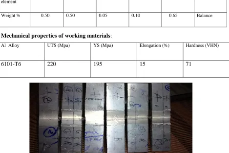
Friction stir welding set-up is developed on vertical milling machine of HMT 1U make at Indian School of
Mines, Dhanbad, India. SS 410 is selected as tool material and aluminium alloy AA 6101-T6 having 6 mm
thickness is selected as working material. AA 6101-T6 is used in making bus bar conductors.Figure 2 shows the
augmented friction stir welding set-up on milling machine. Work piece i.e. aluminium plate is fixed on milling
machine base with the help of fixtures. Tool is fixed on milling machine tool spindle head as shown in figure
.
Table 3:- Different process parameter used for welded samples
Serial No.
Sample No.
Rotational speed(rpm)
Traverse speed (mm/min)
2 1 1 500
3 3 1000 25
4 4 1400 25
5 5 500 40
6 6 710 40
7 7 1000 40
Fig. 3: Experimental setup used for the present study: Friction Stir Welding setup
Chemical composition of Aluminium Alloy 6101-T6
Chemical
element
Si Fe Cu Zn Mg Al
Weight % 0.50 0.50 0.05 0.10 0.65 Balance
Mechanical properties of working materials
:
Al Alloy UTS (Mpa) YS (Mpa) Elongation (%) Hardness (VHN)
6101-T6
220
195
15
71
welding tool has two main parts: shoulder and tapered pin as shown in Fig. The fabricated steel FSW tool has
been heat treated.
Chemical composition of FSW tool material (410
SS):-Constituents Cr Mn Si Ni C P S
Wt % 12.5 1 1 0.75 0.15 0.04 0.03
FSW tool material mechanical properties
:-
Properties Values
Density 7800 kg/m3
Modulus of Elasticity 200 GPa
Melting Range 1482-1532°C
Ultimate tensile strength 517 MPa
yield strength 310 MPa
Poisson’s ratio 0.275-0.285
Tool Design and specification :-
Tool Shoulder Pin
Diameter (mm) Base diameter
( mm)
Top diameter (mm) Length
(mm)
1 25 5 3 5
III. RESULT
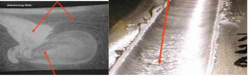
Following types of defects like worm hole, kissing bond, vertical crack, horizontal crack, scalloping, ribbon
flash, surface lack of fill, nugget collapse, surface galling and many more are found in FSW AA6101 T-6 joints
during fesem image study.
Fig. (a): Worm Hole (b). Scalloping
Worm hole [a] is the tunnel of inadequately consolidated andforged material running in the longitudinal
direction which is formed due to excessive heat input due to high rotational speed, low transverse feed.
Defect in which the Series of small voids located in the advancing side interleaving the stir zone along the weld
is known as Scalloping [b].
Fig. :(c). Ribbon Flash, (d). Surface Lack of Fill
Ribbon flash [c] is the excessive expulsion of the material on the top surface leaving a ribbon like effect along
the weld line. Excessive forge load, plunge depth will lead to ribbon flash. On the other hand insufficient forge
pressure, plunge depth will induce surface lack of fill [d] which is a continuous or intermittent top surface void
in the weld line.
Fig.(g).- Horizontal and Vertical crack
Fig(h).-Fesem image of weld crack
Fig
(i)-Fesem image of kissing bond defect (j)Fesem image of Tunnel defectIV. CONCLUSION
1). At high tool rotational speed (i.e. 1400 rpm), defect free welds are obtained. Since, at higher rotational speed
more heat is generated compared to lower rotational speed (i.e. 500 rpm , 710 rpm,and 1000rpm). So material can
2) Tunnel defect was found at the intersection of weld nugget and thermo-mechanically affected zone due to
high rotational speed and travel speed.
3). Selection of improper welding process parameters leads to insufficient heat input, excessive heat input,
abnormal stirring, and insufficient pressure underneath the shoulder which leads to one or more of the defects as
discussed above in the friction stir welding.
4) .Friction stir welding joints are prone to different types of defects which we can eliminate by choosing the
proper tool design and process parameters.
REFERENCES
[1] Ákos Meilinger, Imre Török, “The importance of friction stir welding Tool”, Production Processes and
Systems, 2013, 6 (1), pp 25-34.
[2] R.S. Mishraa,, Z.Y. Ma, “Friction stir welding and processing”, Materials Science and Engineering, 2005,
50. pp 1–78
[3] K.Rajesh guptha, K.Sathish, N.Jeevan kumar, “Analysis of Friction Stir Welding Tools with Various
Threaded Pin Profiles”, International Journal of Engineering Research and Applications, 2013, 3 (1), pp
758- 761
[4] Ramulu P. Janaki, Narayanan R. Ganesh, Kailash Satish V., Reddy Jayachandra, Internal defect and
process parameter analysis during friction stir welding of Al 6061 sheets, International Journal of
Advanced Manufacturing technology 2013; 65: 1515-1528, http://dx.doi.org/10.1007/s00170-012-4276-z.
[5] Thomas WM, Nicholas ED, Needhan JC, Murch MG, Templesmith P, Dawes CJ (1991) International
patent application PCT/GB92/02203 and GB patent application no. 9125978.9.
[6] Wang Wenbin, A stochastic model for joint spare parts inventory and planned maintenance optimisation,
European Journal of Operational Research 2012; 216:127-139,
http://dx.doi.org/10.1016/j.ejor.2011.07.031.
[7] Wojciechowski S., Chwalczuk T., Twardowski P., Krolczyk G.M. Modeling of cutter displacements
during ball end milling of inclined surfaces, Archives of Civil and Mechanical Engineering,
ttp://dx.doi.org/10.1016/j.acme.2015.06.008.
[8] Bernasovsky Peter, Failure analysis of welded components-Importance for technical practice, IIW
International congress in central and east European region Slovakia, High Tatras, 14-16 October 2009.
[9] Podrzaj P., Jerman B., Klobcar D., Welding defects at friction stir welding, Metalurgija 2015; 54 (2):
387-389.
[10] T.L. Teng, C.P. Fung, P.H. Chang, W.C. Yang, Int. J. Press. Vessels Pip. 78 (2001) 523–538.
[11] T. Schenk, I.M. Richardson, M. Kraska, S. Ohnimus, Comp. Mater. Sci. 45 (2009) 999–1005.
[12] Y.S. Sato, H. Kokawa, M. Enomoto, S. Jogan, Metall. Mater. Trans. A 30 (1999) 2429–2437.
[13] C. Genevois, A. Deschamps, A. Denquin, B. Doisneau-cottignies, Acta Mater. 53 (2005) 2447–2458.
[14] W.F. Xu, J.H. Liu, G.H. Luan, C.L. Dong, Mater. Des. 30 (2009) 1886–1893.