INTERNATIONAL JOURNAL OF INTEGRATED ENGINEERING VOL. 11 NO. 8 (2019) 55-64
© Universiti Tun Hussein Onn Malaysia Publisher’s Office
IJIE
Journal homepage: http://penerbit.uthm.edu.my/ojs/index.php/ijie
The International
Journal of
Integrated
Engineering
ISSN : 2229-838X e-ISSN : 2600-7916
*Corresponding author: [email protected]
2000 UTHM Publisher. All right reserved. penerbit.uthm.edu.my/ojs/index.php/ijie
55
Modeling and Speed Control for Sensorless DC Motor BLDC
Based on Real Time Experiment
N. M. Sultan
1, Badrul Aisham Md Zain
1*, Fatin Farhana Anuar
1, M. S. Yahya
2Idris Abdul Latif
3, M. K. Hat
4, Sami Al-alimi
11Advanced Dynamic Control Research Group (ADCARe), Faculty of Mechanical & Manufacturing Engineering, Universiti Tun Hussein Onn Malaysia, Parit Raja, Batu Pahat, Johor, 86400, MALAYSIA
2Centre for Diploma Studies, Universiti Tun Hussein Onn Malaysia, Parit Raja, Batu Pahat, Johor, 86400, MALAYSIA 3Universiti Kuala Lumpur, Gombak, Selangor, 53100, MALAYSIA
4 Politeknik Nilai, Negeri Sembilan, 71760, MALAYSIA *Corresponding author
DOI: https://doi.org/10.30880/ijie.2019.11.08.007
Received 4 February 2019; Accepted 22 October 2019; Available online 15 December 2019
1. Introduction
The DC brushless engine is a versatile motor that is highly demanded in many different fields of application such as electric vehicles, robotics, food and chemical industry. The excellent features of DC motor; high mechanical strength, durability, reliability, effectiveness, portability, speed and cheap cost of maintenance, have placed them ahead as a preferable horsepower control motor [1-2]. This unique DC motor is used mostly in three-phases [3-4] that is driven and controlled by full bridge transistor circuit. The BLDC does not require brush for communication unlike the brushed DC motor, which requires a brush for rotating the rotator. In view of this, it makes BLDC to be economical and environmentally friendly, as they did not generate any electrical or acoustic noise as observed for the mainstream DC motor. Hence, they are deployable in a harsh environment [5-6].
A mathematical model of the system needs to be built through different kinds of thermos for analysing the performance of the control of the system, a process that is not so easy and applicable [7]. Thus, it is important to analyse unknown system and produce an approximate mathematical model that can describe the system through experimental approach [8]. If modelling of the control system can be easily obtained and the control algorithm automatically generates the code, the control system design could be greatly accelerated [9-10].
Abstract: This paper presents the method of modeling the Brushless DC (BLDC) motor without knowing its specific parameters using the system identification. The input and output data were collected and simulated based on the real-time experiment. The potentiometer used to send Pulse Width Modulation (PWM) signals as input signal to (BLDC) motor and LM2907 tachometer attached with (BLDC) motor driver to measure the output speed. The input signal and measured output data were interfaced to plant by C code generation MATLAB/Simulink through Arduino Mega controller. Result presented shows, the system identification process able to obtain the estimates model of BLDC motor with best fit found is 90.2 % which is acceptable. The PID controller was developed to control the desired speed based on the given speed to demonstrate the feasibility of the given method.
This paper proposed the system identification based on real-time experiment to solve the above problems in fast and efficient way. The producer of the system identification system which needs to get the approximate mathematical model of the system, a certain input signal must be loaded, and the device output detected. In order for a good parameters identification system to be optimized, the input signal should have the capacity to holds a wide range of frequency to be able to identify the whole spectrum of plant dynamics [5]. Therefore, closed-loop control speed simulation built and the PID controller are implemented in the system proposed since that proportional–integral derivative (PID) controllers has been used widely in various of applications control system such as speed and position and represented by the question (1) [11-14]. The acronym Kp represent proportion gain coefficient, Ki means integral time coefficient, Kd is differential time coefficient. PID parameters controllers found by self-function of PID controller in MATLAB toolbox. Then, the PID controller implemented with the system’s mathematical model, obtained from the system identification and the response performance of the system was analysed. Based on the simulation results, the system identification process ease to get the mathematical model of any dynamic system using a low-price controller, e.g the Arduino Mega embedded controller [15].
0
( )
( )
( )
( )
t
e
p t d
d t
u t
k e t
k e t dt
k
dt
=
+
+
(1)
1.1 System Structure
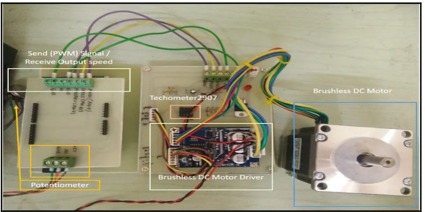
The system structure of the control system consists of the potentiometer, brushless motor with LM2907 tachometer, Arduino Mega 2560 controller as well as brushless DC motor driver and +24 power supply. The Potentiometer sends the signal as PWM to operate the BLDC motor. The installed LM2907 tachometer measures the rotational speed of the BLDC motor starting from the moment the motor starts to rotate.The Arduino Mega controller captured BLDC Motor output speed and send it to the native computer through COM serial communication port to display the captured input signal (PWM), and measured speed in a developed MATLAB/Simulink model.
Fig. 1 - System Structure
The speed generated from the brushless motor is dependent on the PWM signals; if the signal of PWM increased the output speed of the motor will increase, and if the signal of PWM decrease, the output speed will decrease in real time through MATLAB/Simulink simultaneously.
2. Method
2.1 Data Collection
N. M. Sultan et al., Int. J. of Integrated Engineering Vol. 11 No. 8 (2019) p. 55-64
57
Fig. 2 - The serial communication between Arduino, BLDC motor and MATLAB/Simulink with computer
The following are the four stages involved with any experimental process that requires system identification for obtaining the dynamics of a system’s motor [16]:
1) Experiment design and Data collection
The purpose of this step is to collect a large set of data input and output while the system under operation. 2) Determine and define the model structure
Choosing the model structure and find the best model stable. 3) Parameters estimation
Determines the fitting model used to measure the acceptance level based on percentage and recommend the best-fit model. Repeat this step this step till find the acceptance percent which should be >= 90%.
4) Model validation
Model validation and identified used to investigate whether it meets the model requirements.
The flow chart below shows the process of the system identification that used in this project.
Fig. 3 - System identification steps [13]
2.2 Experiment Setup
System identification toolbox [17] is considered an alternative way to model BLDC motor by finding the transfer function of the system. In this work, the potentiometer is varied to send step signal 0-225 to PIN 9 to generate (PWM)
Parameters estimation (model Fitting)
Accepted Model Desgin an experiment and data
collection
Select and define a model structure
Start
Good Model ?
waves to rotate the BLDC motor as shown in Fig. 4. The motor output speed, captured by LM2907 tachometer, is connected to PIN1 in the Arduino Mega controller. The speed coming from the BLDC motor is measured through tachometer transmitted over Arduino Mega microcontroller to host of the computer for the processing the data and model the system. The actual I/O data from the physical system of BLDC motor collected by the Arduino Mega and received by serial configuration port at MATLAB/Simulink in real time.
Fig. 4 - Model for generated input and output data in Simulink
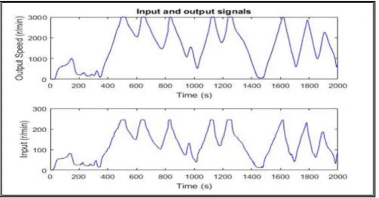
Fig. 4 shown the model generated input and output data used in MATLAB/Simulink model of Arduino controller program with a sampling time T=0.01s in the Simulink model and +24V volt supplied to BLDC motor. The speed of BLDC motor is varied from 0 to 3000 RPM which is the maximum speed of Brushless DC motor. The input signal is PWM signal and the output is BLDC motor’s speed. The motor’s speed and eventual performance will be analysed at no load condition. The input and output signals are exported to MATLAB work area, in where u1 for input variable, y1 for output variable. Fig. 5 shows system identification in MATLAB.
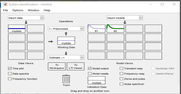
Fig. 5 - System identification
N. M. Sultan et al., Int. J. of Integrated Engineering Vol. 11 No. 8 (2019) p. 55-64
59
Fig. 6 - Input and output data extracted from real time experiment
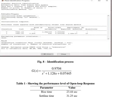
System identification analysis is shown in Fig. 7 where the best fits of the system found is 90.2% after processing the input and output signals in MATLAB’s system identification toolbox. The system’s transfer function is shown in question (2) and as open-loop system.
3. Result and Discussion
3.1 Open-loop response
Open-loop response: Table 1 shows the response parameters of the model determined from the system identification process, which represent the actual response of BLDC motor working efficiency. The system parameters where is on open loop control system without any controller applied to the system model.
Fig. 8 – Identification process
( )
20.9704
1.126
0.07445
G s
s
s
=
+
+
(2)Table 1 - Showing the performance level of Open-loop Response
Parameter Value
Rise time 23.44 sec
Settling time 31.25 sec
Overshoot 11 %
Steady state 13
Fig. 9 shows the poles and zeros obtained from open- loop control system. There is one zero and two poles. From the response shown in Fig. 9, the zero at the left side but poles in right-direction of real-axis which mean the system not stable. In order the system to be stable, both of zeros and poles at the left side of real axis.
Fig. 9 – Poles and zeros of open-loop system
N. M. Sultan et al., Int. J. of Integrated Engineering Vol. 11 No. 8 (2019) p. 55-64
61
3.2 Model Validation
The transfer function of the system obtained was validated by comparing the measured speed output of BLDC motor response with the response gotten from the model, which serves as the transfer function. In the process of validation, the PMW signal was taken as input (yellow color) to model, then comparison between simulated speed and the measured speed (black color) was made. Fig. 10 show the response of the transfer function (red color) is fitted the measured output speed of the BLDC motor.
3.3 A closed-loop System simulation
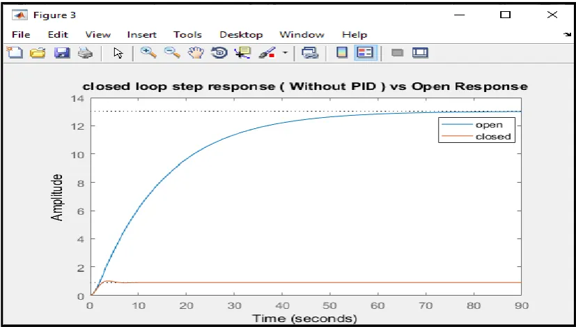
In the simulation, the speed control was represented by a closed system in evaluating its transfer function, using MATLAB Software. Fig.11 shows the closed response of the system without any controller has been applied. As it can be seen, the response has improved where the step signal reduces settling time and rise time. However, overshoot has been increased. Since the overshoot of the system increased, the system will be influenced by PID controller to reduce the overshoot and to improve the system response for better performance in a real application.
Fig. 10 - Model validation of transfer function
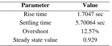
Table 2 – Performance indicator of closed-loop response
Parameter Value
Rise time 1.7047 sec
Settling time 5.70064 sec
Overshoot 12.57%
Steady state value 0.929
3.4 PID Simulation Result
The transfer function in question (2), obtained based on system identification, was employed to develop a traditional PID controller to control the speed based on the desired speed given using question (1). Fig. 12 shows the complete model that represents the PID controller in MATLAB/Simulink. The estimated error e(t) in between the desired and the generated speed of the plant is fed into the controller. However, the controller will adjust the entering signal to the model as a suitable value based on error given to the brushless DC motor, so it can achieve the desired speed with fast response and reducing the overshoot and settling time of the system.
Fig. 12 – Model PID controller for speed control
MATLAB PID tuner provides the suitable method for tuning PID controller’s parameters. The basis of PID tuner is on the MathWorks theorem to turn the PID controllers to achieve the fast-dynamic performance, stability, and robustness of the control system. If the PID gains is tuned, it can make the system to perform at its peak by reducing settling time, rise time and overshoot of the system. In this work, we have tuned the PID controller to obtain the preffered response rate of the BLDC motor produced from the system identification modeling technique. The PID parameters obtained after tuning are Kp= 50, Ki = 101 and Kd= 18.
N. M. Sultan et al., Int. J. of Integrated Engineering Vol. 11 No. 8 (2019) p. 55-64
63
3.5 PID tuning speed control Simulink
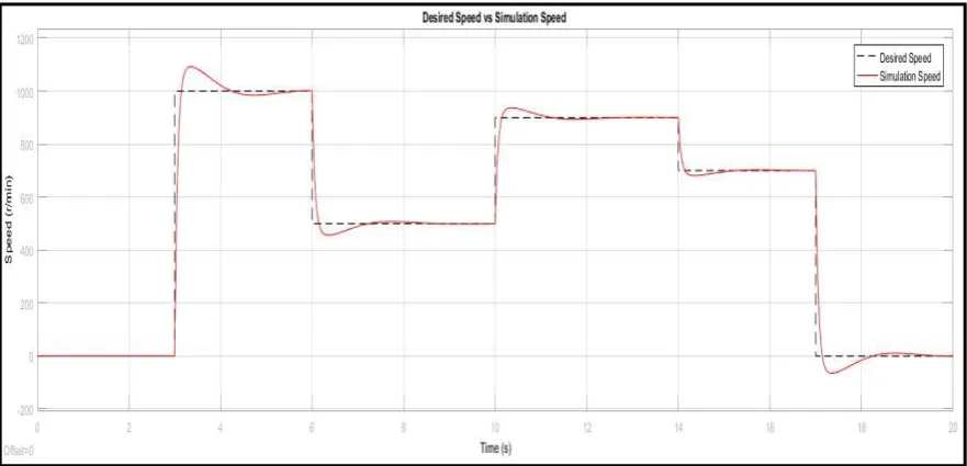
The accuracy of response of the BLDC motor model is established by simulating the model with the tuned PID parameters obtained and output plot analysis. The output of automated model for the PID control parameters and replicated close motor speed is shown in Fig. 14. Sort of desired speeds given as the input to the model with 800, 600 and 1100 RPM respectively as indicated in black colour and PID response indicated the red colour. PID response followed to the given values of desired speed. Since PID response followed the given speed even though that the speed varied continuously, tuned PID controller has succeeded in controlling the model’s speed, in accordance to the desired speed given, even if any load is applied to control system because the auto-PID controller will maintain the stability of the system as desired speed. To vary simulation speed of tuned PID control, another set of desired speeds given (1000,500,900,700 and 0 RPM) to model in closed-loop motor speed as Fig. 15. Based on the PID response of these new data, the response of the system is tracked the desired speed as it can be seen in Fig.16 and validated that the system is under the PID controller. Based on Table 3 the parameters of tuned PID controller speed controller, the system parameters improved, and which indicated tuned PID controller maintain the system stability and robustness under the changing of the speed.
Fig. 14 – Simulation of PID controller model response with speed control
Fig. 15 – Varying the PID controller based on desired speed given
4. Conclusion
objective of studying the actual response is to find the response parameter of the control system. Transfer function has been used in system identification to estimate the best fit between the input and the measured data and found 90.2% which is acceptable. Model validation has been done by comparison between the data input and measured output speed. Simulink of PID closed-loop control is established for an identification system. Finally, a sort of desired speed given to the PID closed-loop control to find the output speed response of the system which finds that the output speed is tracked the desired speed given which indicated the control system has good dynamic performance and precision as the simulated result obtained. Future work, this work will carry out in real-time control with obtained tuned PID controller system
Table 3 – Performance indicator of closed-loop response
Parameter Value
Rise time 0.0214 sec
Settling time 0.0406 sec
Overshoot 7.57 %
Steady state value 0.825
Acknowledgement
The author would like to acknowledge the financial support received from the Research Management Center (RMC) Universiti Tun Hussein Onn Malaysia (UTHM) under the Tier 1 Research Grant Scheme (Code H242).
References
[1] Lakshmi S K, Kunapareddy, & T B., (2014). Modeling and controlling of BLDC motor, S.A. Engineering College, Chennai, Tammil Nadu, India, ICICES.
[2] A. Tashakori, M. Ektesabi and N. Hosseinzadeh., (2011). Modeling of BLDC motor with ideal back-EMF for automotive applications, The World Congress on Engineering, No.2.
[3] Miller, & T. J. E. (1993). Switched Reluctance Motors and their Control. Oxford, UK, Magna Phys. Publication and Clarendon, 40-90.
[4] Khader, & S. H. (2001). Implementation of an accurate mathematical method for modeling electromagnetic processes of brushless DC Motor. MESM, Amman, Jordan, 31-38.
[5] Fachinger, & J. (2006). Behavior of HTR fuel elements in aquatic phases of repository host rock formations. Nuclear Engineering & Design, 236, 54.
[6] Atmel Corporation. Brushless DC Motor Control Using ATMega 32MI. June 2018.
[7] G. Prasad, N.S. Ramya, P.V.N. Prasad, & G.T.R. Das. (2012). Modelling and simulation analysis of the brushless DC motor by using MATLAB. International journal of innovative technology and exploring engineering (IJITEE), pp. 27-31.
[8] Wei-Jie Tang, Zhen-Tao Liu, & Qian Wang, T B. (2017). DC motor speed control based on system identification PID Auto Tuning. Proceeding of 36th Chinese Control Conference, China, July 26-28.
[9] Berenji, & Hamid, R. (1992). Fuzzy logic controllers.
[10] Coolen, & A. C. C., (1998). A beginner’s guide to the mathematics of neural networks. Concepts for Neural Network, 13-70. http://doi.org/10.1007/978-1-4471-3427-5_2.
[11] Wang, & S.-C. (2003). Artificial Neural Network. In Interdisciplinary Computing in Java Programming (pp. 81– 100). Boston, MA: Springer US. http://doi.org/10.1007/978-1-4615-0377-4_5.
[12] Solihin M., Tack L. & kean, M. (2011). Tuning of PID controller using particle swarm optimization (PSO). In: International Scientific Conference 2011. IJASEIT. DOI:10.18517/ijaseit.1.4.93.
[13] Anuar F F, Zain B A M & Al-Shaibani N (2018). Comparative study on flexible link aerator using arduino programming and dissolved oxygen meter Int. J. Integr. Eng. (IJIE) 10 1–5.
[14] Akbarimajd A (2015). Reinforcement Learning Adaptive PID Controller for an Under-actuated Robot Arm Int. J. Integr. Eng. (IJIE) 7 20–7.
[15] Annisa J, Darus I Z M, Tokhi M O & Abidin, A S Z. (2018). Controlling the non-parametric modeling of double link flexible robotic manipulator using hybrid PID tuned by P-Type ILA Int. J. Integr. Eng. (IJIE)10 219–32. [16] Yusoff A H M, Salleh S M, Abdullah M E, Zaman I, Hani M H M, Siswanto W A & Mahmud W A W. (2018)
Experimental evaluation of fish feeder machine controller system Int. J. Integr. Eng. (IJIE) 10 218–22.
![Fig. 3 - System identification steps [13]](https://thumb-us.123doks.com/thumbv2/123dok_us/8433948.1698785/3.595.103.494.71.229/fig-system-identification-steps.webp)