© Universiti Tun Hussein Onn Malaysia Publisher’s Office
IJIE
Journal homepage:http://penerbit.uthm.edu.my/ojs/index.php/ijie ISSN : 2229-838X e-ISSN : 2600-7916
The International
Journal of
Integrated
Engineering
Compressive Behavior of Jacketed Specimens and Flexural
Behavior of Concrete Beam Strengthened using Sodium
Silicate Mortar
Taufiq Ilham Maulana
1,*, Dimas Irfani1Author
11Department of Civil Engineering, Faculty of Engineering,
Universitas Muhammadiyah Yogyakarta, Special Region of Yogyakarta 55183, INDONESIA
*Corresponding Author
DOI: https://doi.org/10.30880/ijie.2019.11.09.028
Received 21 February 2019; Accepted 16 October 2019; Available online 31 December 2019
Abstract:Damage in concrete structures depends on the load types. Flexural and axial loads are the most common load types that cause damages. The damage can be repaired by injecting materials such as sodium silicate. In this study, two methods are performed to repair concrete damages namely grouting in beam and jacketing on concrete cube samples with sodium silicate mortar. The grouting method was conducted in the first crack of beam, while the jacketing method was done by covering the concrete cube with sodium silicate mortar. The sample used was 15x15x15 cm3 of concrete cube and 15x15x60 cm3 of beam. The results showed that sodium silicate mortar improved 92% compared to the initial stage of compressive strength. However, the first crack at maximum load of the repaired beam occurred earlier than the controlled specimen. In general, the repairing method can be applied to reduce damage in concrete structures.
Keywords:Damage concrete, crack, grouting and jacketing, sodium silicate mortar
1. Introduction
Concrete is a non-ductile material that is formed by mixing cement, water, fine aggregate and coarse aggregate. Concrete is very often used to support compress load due to its hard nature. However, its brittle nature after the mixture hardens makes it vulnerable to damage and cracking. Concrete damages that usually occur are shear, flexural and axial failure. Shear and flexural failures commonly occur in beam structures, while axial failure occurs in column elements. Many researchers have studied concrete failures and the repairing methods.
Yang et.al. [1] studied a beam with flexural failure which was repaired by composite external reinforcement using carbon fiber reinforced polymer grid and cementitious matrix. The first stage of this research was to numerically estimate the target capacity of the beam. The ratio of targeted capacity to experimental test was determined about 1.05.
The other researcher also investigated the similar issue using different materials, i.e. ground rubber tire powder incorporated textile in RC [2]. This rubber was retrieved from wasted materials which used about 2.5% to 7.5%. Jayaprakash et.al. [3] used carbon fiber fabric to reinforce a beam under shear load. This fiber has tensile strength of 3.8 MPa with Young’s modulus of 230,000 MPa. The study was done by numerical and experimental analyses. The finite element analysis was modelled by LUSAS. The results concluded that there is a similarity between numerical and experimental analyses. The use of fiber increases 50% from the initial shear strength.
applied the repair materials to concrete due to cyclic load which illustrates the earthquake. The result showed that this type of strengthening could improve the column performance after severely damaged. Another study on axial structural member improvement has also been developed using concrete jacket with reactive powder (RPC) and carbon fiber reinforced polymer (CFRP) wrapping [5]. This study had cylindrical specimens with reinforcing bar inside the concrete. The thickness of the material was about 25 mm from outside of the specimen. There were several parameters observed in this experiment, namely ductility, ultimate axial load, and energy absorption. The result showed that strengthening by CFRP for concentric axial load on repairment has shown to be significantly higher than the controlled specimen, and it has higher ductility compared to that strengthened with jacketing. The proposal of jacketing technique was also suggested to gain the yield load.
Several researchs have investigated the repairing concrete element by jacketing ([6], [7], [8]). Alhadid and Youssef [6] did numerical analysis based on experimental test from another research to evaluate the strength of concrete beam after jacketing with concrete layer. The study recommended the modification factors to calculate deflections and capacity of repaired specimen. Concrete jacketing for structural member has also been studied for column under compressive load [7] and for substandard reinforced concrete column [8]. The use of Steel-Reinforced Grout (SRG) was the main point of the repair for both studies. The samples made were cylindrical concrete layered with SRG. It is proved that adding SRG for repair could increase the compressive strength.
Researches on the application of Sodium silicate in concrete have been performed previously. One study has observed the utilization of Sodium silicate for mortar [9]. The results indicated that this kind of materials is better than conventional materials, not only in terms of the compressive strength, but also in terms of the resistance of water. Another researcher also sought for the tensile strength and microstructure of the Sodium silicate on geopolymer application ], confirming that Sodium silicate enhanced the tensile strength resulted from the shrinkage and micro-cracks. Sodium silicate was also proved to be better than cement itself when reacting in mortar, in this case OPC mortar [11]. In binder structure, this material also increases the extent of crosslinking and has higher alkalinity which gives a more gel structure that is good for structural materials [12],[13]. In slag concrete, Sodium silicate has a good effect on increasing compressive strength [14]. Also, the workability of cementless mortars with sodium silicate is greater than that with OPC mortars [15]. ]. In any structural members, Sodium silicate has been applied in geopolymer concrete beam structure [16], double-walled self-healing concrete structural members [17], and even for coating to receive humidity resistance in heating condition [18]. The benefits of this material have been proved especially for concrete in construction materials.
However, a mix of sodium silicate with cement has not been tested to be applied for improving structural members. In this research, Sodium silicate was demonstrated to be used for improving damaged concrete samples due to compressive test by jacketing and for repairing the first crack on beam due to flexural testing by grouting. The purpose of this study was to know the effectiveness of using Sodium silicate mortars for repairing axial and flexural structure members. The compressive strength and interaction between load and displacement became the parameters to give the complete images of the mortar effectiveness. Furthermore, this study also contributed as a reference to researches on structural repair.
2. Materials and Samples
Local materials for the concrete were used in this study. The fine aggregate was from Mount Merapi area while the coarse aggregate was from Clereng, Yogyakarta. Material properties tests were performed to understand their characteristics for mix design purposes. There were two types of samples used in this study: one was the cubical concrete specimens and the other was reinforced concrete beams. The reinforcing bars used two diameters, namely 6 mm and 8 mm. The 6 mm was used for confinement reinforcement and the 8 mm was for the longitudinal bars.
2.1 Fine and Coarse Aggregates
Distribution size of the fine aggregate was checked to know whether it could be used or not as concrete mix. The Indonesian Standard (SNI) was referred to as guidance for the test, which in this case was based on SNI 8321:2016. The result of the distribution size is illustrated on Fig. 1. The fine aggregate passing cumulative used was slightly under the lower limit than the allowed especially on small sieve size, however this material was still acceptable for mix concrete.
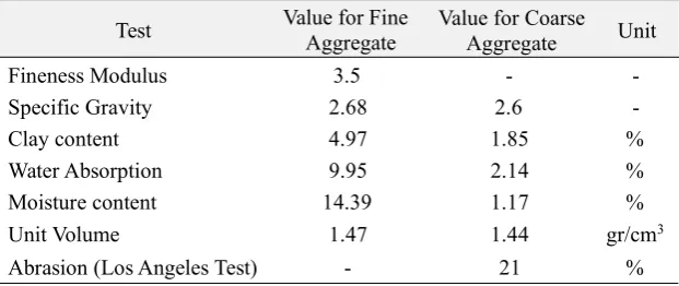
Different with the fine aggregate, the distribution size test for coarse aggregate used in this study was not performed since the material particles had been maintained to be retained at the sieve with size of 20 mm and passed the size of 40 mm. Many types of tests were done to obtain the fine and coarse aggregate properties. These tests were directly related to the determination of ratios among all the materials for concrete mixing as well as the requirements needed from SNI. Below in Table 1, the properties test results are shown.
2.2 Concrete Mix Design
Based on the design, it was suitable to use the water–cement ratio of 0.48. The proportion of water, cement, fine and coarse aggregates for the cube and beam concrete specimens can be seen in Table 2 below. For the record, these proportions are not for 1m3but for making 1 sample with the designated size.
Fig. 1 - Fine aggregate distribution size
Table 1 - Material Properties test for fine and coarse aggregate
Test Value for FineAggregate Value for CoarseAggregate Unit
Fineness Modulus 3.5 -
-Specific Gravity 2.68 2.6
-Clay content 4.97 1.85 %
Water Absorption 9.95 2.14 %
Moisture content 14.39 1.17 %
Unit Volume 1.47 1.44 gr/cm3
Abrasion (Los Angeles Test) - 21 %
Table 2 - Details of concrete compositions
Materials Value for
cube specimens
Value for
beam specimens Unit Water Cement Fine Aggregate Coarse Aggregate 0.76 1.58 2.14 6.46 3.04 6.33 8.56 15.9 Litre kg kg kg
Total 8.46 33.85 kg
2.3 Tensile Strength of Reinforcing Bars
Beam specimen cannot withstand itself without reinforcing bars. There are two possibilities of failure in the beam, namely flexural and shear failure. It is expected to fail from bending test, so that the shear strength must be stronger than its flexural. Two varieties of reinforcing bars were installed in the concrete, one had 6 mm of diameter and the other had 8 mm. These two bars were tested under the tensile test on universal testing machine (UTM). The 6 mm bar had yield stress (fy) about 250MPa to 350 MPa and the 8 mm bar had about 350MPa to 420 MPa. Fig. 2 presents the
complete result of the bar testing.
2.4 Cubical Concrete Specimens
calibration to normal compressive strength (f'c) with a multiplier of 0.83. Below in Fig. 3 and Fig. 4 are displayed the
concrete cube moulds and the implementation of curing of concrete samples.
Fig. 2 - Stress-strain interaction of reinforcing bar used
Fig. 3 - Cubical concrete mould
Fig. 4 - Cube specimens inside the water for curing
2.5 Reinforced Concrete Beams
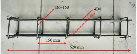
Four reinforced concrete beam samples were used with 1 control beam which was not repaired. Three other samples were distinguished based on sodium silicate to cement ratio which was for grouting applied. The beam had a rectangular section of 15 cm x 15 cm with a total span of 62 cm. Moreover, the support was pinned-rolled support with a span length of 60 cm. The beam had the reinforcement configuration as depicted in Fig. 5 with the illustrated cast in Fig. 6. After cast, the concrete was cured by covering it using a wet gunny sack for 28 days, as pictured in Fig. 7.
Fig. 6 - Concrete beam metal cast
Fig. 7 - Beam samples curing process
2.6 Sodium Silicate and Cement
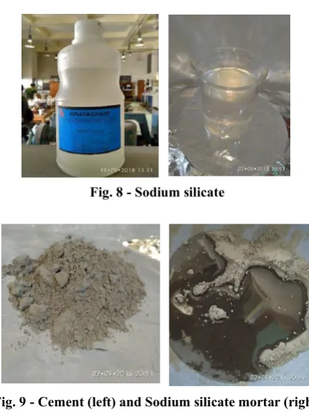
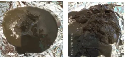
Sodium silicate, or usually called as water glass, is the name for chemical compound of Na2SiO3. This chemical was obtained from Bratachem, Indonesia. Its form is liquid so that it can directly be mixed with cement. This compound can be seen in Fig. 8. The cement used for this research was Portland Pozzolan Cement with “Semen Gresik” brand and the mixing between Sodium silicate with the cement to create Sodium silicate mortar is illustrated in Fig. 9.
Fig. 8 - Sodium silicate
Fig. 9 - Cement (left) and Sodium silicate mortar (right)
3. Experimental Tests
bending tests for the beam specimens were performed by Universal Testing Machine (UTM) in this laboratory as seen in Fig. 10. For the bending test, the UTM was modified with some additional supporting steels to conduct three-point loading as suggested in ASTM C78. The configuration of the support system with modified steel can be seen in Fig. 11.
In this experiment, there were three main parameters observed during the test, namely compressive strength for the cubical specimens and load-displacement interaction for the beam samples for both condition, initial condition at an age of 28 days and after the strengthening using Sodium silicate.
The jacketing method for the cubical concrete samples was by using an additional casting from multiplex wood, which is presented in Fig. 12. This casting had a dimension of 16 x 16 cm2so that it left small gaps around the cube to be filled with sodium silicate cement. Different with the compressive test samples, the beam was repaired by making the first crack and the load for the first crack was predicted by manual calculation before the real test. After the first crack appeared, then the beam was prepared to be injected by sodium silicate mortar along its crack, then the bending test was continued on the next 28 days for its final age. This treatment is shown in Fig. 13.
Fig. 10 - Testing set up for concrete cube sample
Fig. 11 - Testing set up for beam sample
Fig. 12 - Concrete cube jacketing treatment
Sodium Samples Sil icate-Ceme nt
Initial Test Result after Jacketing Residual Strength (100% -differenc Compressive Average Compressive Average
Strength (MPa) Strength (MPa) (%)
(MPa) (MPa)
4. Results and Discussion
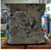
The very first test in this experiment was Slump test. The average result obtained from this test was 13.7 cm, which was still acceptable since the requirement from SNI 1972:2008 was between 7.5 to 15 cm so the workability of the mixture was good. After that, the concrete was casted and tested with axial load to know the compressive strength. The result showed that the failure at the cubical concrete specimens was the same as predicted previously, which had compression failure. This failure is illustrated in Fig. 14. The specimen had a lot of spoiling especially on its body parts.
Fig. 14 - First attempt on concrete cube sample compressive test
Following this test, the same specimen went to multiplex wood cast and filled with sodium silicate mortar so that it covered all the surrounding of the cube. This represents the attempt to do a jacketing on structural member which has failed from axial test. The jacketed specimen is presented in Fig. 15.
Fig. 15 - Jacketed cubical concrete specimen with sodium silicate
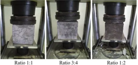
There were three proportions of sodium silicate–cement ratio that were used in this study, namely 1:1, 3:4, and 1:2. The UTM machine can only read the maximum load so only the ultimate compressive strength can be known.
The first compressive test indicated that all the three ratios had the compressive strength more than 30 MPa as designed in the beginning. After the jacketing, these three ratios were tested again due to axial load and still had good average ultimate strength at least 72% from the initial strength for ratio 1:1 and 92% for ratio 3:4. This shows that the sodium silicate mortar really helped the cubical concrete to retain all the axial forces that occurred during the test, even though the repaired concrete could not go back to its full strength. The detail of the compressive test result for both conditions is presented in Table 3 while the damage during the test is depicted in Fig. 16.
Table 3 - Compressive test result for cubical concrete specimens
TA1 26.16 21.35
TA2 1:1 39.75 32.65 24.14 23,48 28% 72
TA3 32.04 24.96
TA4 39.53 33.27
TA5 3:4 32.71 31.49 34.41 28,91 8% 92
TA6 22.25 19.05
TA7 36.41 32.74
TA8 1:2 40.38 37.93 41,13 33,34 12% 88
After the test, these three ratios were observed closely to see the types of the damages. From Fig. 17, it can be known that ratio 1:1 and 1:2 were mostly damaged on the outer part, which is the sodium silicate mortar, while the ratio 3:4 had all the damages on its body.
Fig. 16 - Failure at the compressive test for strengthened cubical specimens
Fig. 17 - Detailed failure occurred in jacketed concrete cubes
The next experiment was bending test for beam specimens. The first crack that occurred in the beam was placed in the middle of the beam as illustrated in Fig. 18. This means that the beam had been damaged from the flexural failure. After retrieving the first crack, the injection of sodium silicate mortar grouting was done especially in the part of openings, then bending re-test was performed until the ultimate strength was obtained. The final failure on the three beams is depicted in Fig. 19.
Fig. 18 - Crack happens on beam samples for the first attempt
Fig. 19 - Bending failure for three grouted beams
There were three beam specimens involved in this test, with different Sodium sillicate-cement ratios (SSCR). Beam 1 (B1), Beam 2 (B2) and Beam 3 (B3) had the SSCR of 1:1, 3:4, and 1:2 respectively. The load and displacement were observed to know the detail of P-delta curves. The first crack was also monitored, and all the first cracks were shown in Fig. 20 with different colors. After the crack, the beam was repaired then the loading was continued until all the specimens failed. The dashed lines illustrate the crack point and ultimate point of the control specimen results. These are drawn in Fig. 20 to compare all the results.
From the test outcome, it can be learned that the load to make the first crack of the repaired beam was not as high as the control beam which is possibly because the sodium silicate was not fully covered and did not have enough grip to maintain the beam concrete especially on the gap. Similar with the ultimate strength, the load to make the control beam reach the ultimate condition was still higher than the load for all the three beams.
Fig. 20 - Bending test result of beam specimens.
Table 4 Detailed result of bending tests for beam specimens. Conditi Code Pu Displacement
B 2.57 1.
Initial First crack before repairment B 2.66 0.
B 2.65 0.
B 1.89 1.
Crack after repairment B 1.92 2.
B 2.21 1.
B 5.32 7.
Ultimate condition after repaired B 4.63 12.
B3 6.21 8,69
Crack on Controlled Beam Dashed line 2.60 Not recorded
Ultimate Condition on Controlled Beam Dashed line 2
6.31 Not recorded
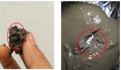
In addition to the test result, it is noticed that the sodium silicate mortar had a short setting time, so the strengthening had to be done quickly before the mortar hardened. Fig. 21 shows the mixing condition of this mortar. In only 7 minutes, the mortar had already set so that it was hard to fill the crack gap. In 10 minutes, the mixture had partly hardened and created some clogs as illustrated in Fig. 22. This quick setting time might also be the reason of the lower bending test result for repaired specimen compared to controlled beam.
Fig. 22 - Clogging that happened in sodium silicate mortar after 10 minutes.
5. Summary
To sum up, sodium silicate can be mixed with cement and becomes a good material of mortar. This mortar is able to strengthen the cubical concrete specimens about 72% to 92% to its first strength due to compressive load. However, this shows different result on beam specimen, where the crack and the ultimate load are not higher than those of control beam. This might be caused by a short setting time, so it is hard for mortar to completely fill crack gaps and hold concrete surrounding it. Hence, this material and repairing method are introduced as a reference for future researches and for practical engineers’ consideration to repair concrete with axial damages.
References
[1] Yang, X., Gao, W. Y., Dai, J. G., Lu, Z. D., & Yu, K. Q. (2018). Flexural strengthening of RC beams with CFRP grid-reinforced ECC matrix. Composite Structures, 189, 9-26.
[2] Gopinath, S., Bonadies, I., Carfagna, C., & Maheswaran, S., Ramachandra, M. A., & Iyer, N. R. (2018). Investigations on ground rubber tire powder incorporated textile reinforced concrete for flexural strengthening of RC beams. Journal of Structural Engineering, 44(6), 605-612.
[3] Jayaprakash, J., Samad, A. A. A., Koh, H. B., Anwar M. P., & Mohamad, N. (2015). Experimental and finite element studies strengthened RC rectangular beams in shear on CFF. International Journal of Integrated Engineering, 7(1), 29-38.
[4] Cho, C. G., Han, B. C., Lim, S. C., Morii, N., & Kim, J. W. (2018). Strengthening of reinforced concrete columns by high-performance fiber-reinforced cementitious composite (HPFRC) sprayed mortar with strengthening bars. Composite Structures, 202, 1078-1086.
[5] Hadi, M. N. S., Algburi, A. H. M., Sheikh, M. N., & Carrigan, A. T. (2018). Axial and flexural behaviour of circular reinforced concrete columns strengthened with reactive powder concrete jacket and fibre reinforced polymer wrapping. Construction and Building Material, 172, 717-727.
[6] Alhadid, M. M. A., & Youssef, M. A. (2017). Analysis of reinforced concrete beams strengthened using concrete jackets. Engineering Structures, 132, 172-187.
[7] Thermou, G. E., Katakalos, K., & Manos, G. (2018). Experimental investigation of substandard RC columns confined with SRG jackets under compression. Composite Structures, 184, 56-65.
[8] Thermou, G. E., & Hajirasouliha, I. (2018). Compressive behaviour of concrete columns confined with steel-reinforced grout jackets, Composites Part B: Engineering, 138, 222-231.
[9] Haq, E. U., Padmanabhan, S. K., Abdul Karim, M. R., & Licciulli, A. (2016). Setting and curing of mortars obtained by alkali activation and inorganic polymerization from sodium silicate and silica aggregate. Construction and Building Materials, 105, 291-296.
[10] Billong, N., Kinuthia, J., Oti, J., & Melo, U. C. (2018). Performance of sodium silicate free geopolymers from metakaolin (MK) and rice husk ash (RHA): Effect on tensile strength and microstructure. Construction and Building Materials, 189, 307-313.
[11] Yang, K. H., Song, J. K., Ashour, A. F., & Lee, E. T. (2008). Properties of cementless mortars activated by sodium silicate. Construction and Building Materials, 22 (9), 1981-1989.
[12] Bernal, S., Nicolas, San, R., Provis, J., & van Deventer, J. S. J. (2015). Alkali-activated slag cements produced with a blended sodium carbonate/ sodium silicate activator. Advances in Cement Research, 28(4), 1-12.
[13] Bernal, S. A., Provis, J. L., Rose, V., & Mejía De Gutierrez. R. (2011). Evolution of binder structure in sodium silicate-activated slag-metakaolin blends. Cement and Concrete Composites. 33 (1), 46-54.
[14] Taghvayi, H., Behfarnia, K., & Khalili, M. (2018). The effect of alkali concentration and sodium silicate modulus on the properties of alkali-activated slag concrete. Journal of Advanced Concrete Technology, 16(7), 293-305. [15] Yang, K. H., and Song, J. K. (2009). Workability loss and compressive strength development of cementless
[16] Ngernkham, T. P., Maegawa, A, Mishima, N., Hatanaka, S., & Chindaprasirt, P. (2015). Effects of sodium hydroxide and sodium silicate solutions on compressive and shear bond strengths of FA-GBFS geopolymer. Construction and Building Materials, 91(1),1-8.
[17] Mostavi, E., Asadi, S., Hassan, M. M, &Alansari, M. (2015). Evaluation of self-healing mechanisms in concrete with double-walled sodium silicate microcapsules. Journal of Materials in Civil Engineering, 27(2), 04015035. [18] Liu, F., Fan, Z., Liu, X, Huang, Y., & Jiang, P. (2016). effect of surface coating strengthening on humidity