on Wireless Spectrum
Research Article
1
Interference-Aware Hybrid MAC protocol for Cognitive
Radio Ad-Hoc Networks with Directional Antennas
Satish Anamalamudi
1, Minglu JIN
1and Jae Moung Kim
2,*
1 School of Information and Communication Engineering, Dalian University of Technology, Dalian, P.R.China. 2School of Information and Communication Engineering, Inha University, Incheon 402-751, Korea.
Abstract
CR and PU hidden terminals in multi-channel Cognitive MAC protocols result in increased packet drops. This is due to inefficient node synchronization with existing “Control Channel” design. To date, In-band and Out-of-band CCC based MAC protocols are proposed to avoid PU and CR hidden terminals. But, In-band CCC based CR-MAC protocols cannot efficiently resolve the hidden terminal packet drops due to imperfect node synchronization whereas out-of-band CCC based MAC is vulnerable to intruder attacks and channel saturation. To overcome this, we propose an Interference-aware hybrid CCC cognitive MAC protocol with directional RTS/CTS and data transmission. In addition, adaptive power control algorithm is proposed to avoid interference to hidden PU and CR nodes at edge coverage area. Experimental results show that proposed Hybrid cognitive MAC protocol has increased link aggregate throughput and reduced cognitive control overhead in comparison with existing CCC based CR-MAC protocols.
Keywords: Node synchronization, Multi-channel hidden terminals, Cognitive Radio, Common Control Channel.
Received on 30 June 2015, accepted on 01 July 2015, published on 16 July 2015
Copyright © 2015J. M. Kimet al., licensed to ICST. This is an open access article distributed under the terms of the Creative Commons Attribution licence (http://creativecommons.org/licenses/by/3.0/), which permits unlimited use, distribution and reproduction in any medium so long as the original work is properly cited.
doi: 10.4108/ws.1.3.e1
1. Introduction
Natural available spatial spectrum is scarce and cost effective. In order to efficiently utilize the available frequency bands, it is significant to change the current static spectrum allocation and its management policies. This is because most of the allocated static spectrum bands are not effectively utilized with respect to time, frequency and geographical location. From this, it is noteworthy that existing spectrum scarcity issue is due to current static allocation rather than physical spectrum availability. On the other hand, new wireless services are getting deployed in heavily regulated spectrum bands that result in increased demand of spectrum. To overcome the spectrum deficiency [1], Federal Communication Commission (FCC) has introduced a new concept called Dynamic Spectrum Access (DSA). With this, unused spectrum holes are efficiently utilized through Software Defined Radio (SDR). Cognitive
Radio (CR) is a special type of Software Defined Radio that can change its operating parameters (modulation, frequency and data rate) dynamically based on environmental conditions [2]. To deploy cognitive radio in real networks, it is important to enhance the existing TCP/IP protocol stack to support dynamic spectrum access, spectrum mobility and SDR functionalities. To accomplish this, protocols in every layer of TCP/IP protocol stack should be modified or new protocols should be designed for cognitive radio deployment in existing traditional ad-hoc networks [3]. In cognitive Radio, secondary users should perform spectrum exploration and exploitation to opportunistically share the spectrum bands without interrupting the Primary User (PU) communication [4]. Hence, interference with PU and neighbour CR nodes need to be addressed to avoid the packet drops at link and network layers. In addition, spectrum mobility due to dynamic PU active, node handover and channel degradation is equally important to enhance the performance of cognitive radio networks.
State-*Corresponding author. Email: [email protected]
EAI
European Alliance for InnovationEAI
European Alliance for InnovationEAI
European Alliance for InnovationEAI
European Alliance for InnovationEAI
European Alliance for InnovationEAI Endorsed Transactions on Wireless Spectrum 05-07 2014|Volume 01|Issue 2|e2
of-the-art research doesn’t explore much on MAC level interference management where minimizing packet drops due to edge PU and CR hidden terminals are significant for both primary and secondary networks [5]. To accomplish this, we propose an “Interference-aware hybrid cognitive MAC protocol” with synchronized TDMA based Slotted Co-ordination Function (SCF) for cognitive control message exchange and traditional CSMA/CA based Distributed Co-ordination Function (DCF) for directional data transmission. The rest of the paper is organized as follows. Section.2 briefly explains about the current existing works on In-band and out-of-band CCC-CR-MAC protocols with clear advantages and disadvantages. Section.3 briefly explains about the SCF and DCF function in proposed Interference-aware hybrid CCC-CR-MAC protocol. Subsequently, a new packet buffering mechanism is proposed to handle the node mobility and spectrum mobility packet drops at link level. Moreover, an adaptive power control algorithm is explained to avoid the collisions with hidden PU receivers at edge coverage area. Experimental results are explained in Section. 4, whereas conclusion and future work is explained in Section.5.
2. Related Works
Control and data transmission in existing CSMA/CA is based on unlicensed ISM spectrum bands. In the sense, 2.4 GHz or 5 GHz fixed static ISM bands are used a shared channel in traditional wireless networks for control and data
transmission. Interference due to concurrent
communications in single channel IEEE 802.11 DCF is avoided through virtual carrier sensing (RTS/CTS). To minimize poor channel utilization and enhance the link throughput, multi-channel MAC protocols were proposed in non-overlapping ISM channels. In multi-channel MAC, one non-overlapping ISM channel is assumed to be available for control message exchange. During control slot, all nodes within the network will tune to pre-defined control channel for node synchronization and channel contention to avoid packet drops due to multi-channel hidden terminals. During data transmission, nodes within the network will tune to selected data channel for data transmission. The basic operation of MAC protocol in cognitive radio networks is very similar to multi-channel MAC protocol with the exception of usage of static unlicensed channel [6]. That is, licensed opportunistic PU free spectrum bands are used for control and data transmission in cognitive MAC protocol. This results in non-availability of fixed common control channel (CCC) in CR-MAC protocols for node synchronization and cognitive control message exchange. To resolve the control channel problem in cognitive radio, state-of-the-art research proposes In-band or out-of-band CCC based CR-MAC protocols in overlay spectrum bands [7].
Ch-i
Ch-j
PU Ch-i
collision
Sensing range
T-1
T-2 T-2
T-1
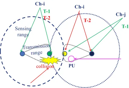
Figure 1. Multi-channel hidden terminal with sequential
CCC based CR-MAC protocol.
3 ( )
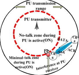
Figure 2. PU receiver interference due to CR node mobility.
( )
Figure 3. PU receiver interference due to CR spectrum
mobility.
CR nodes that are in minimal-talk zone can reduce it’s transmit power to avoid interference with PU signal. During CR node mobility from minimal-talk zone to no-talk zone sender CR signal can interfere with the hidden PU receiver at edge locations that is shown in Figure.2. At this time, when CR node use same transmit power then the will be packet drops at PU receivers in no-talk zone. To avoid this, we propose adaptive power control algorithm to reduce CR node transmit power dynamically. Whenever, minimal transmit power is subject to interference then CR nodes need to find another opportunistic PU free channel to continue its communication. Figure.3 explains about the spectrum mobility packet drop scenario at minimal-talk zone. CR nodes that are in minimal-talk zone can use same channel when PU is ON/OFF. Let us consider a scenario where PU receiver is active at the edge coverage of no-talk zone and the CR node is very near to no-talk zone. At this point, secondary data transmission in same channel of PU causes interference to PU receiver at no-talk zone. Existing power control algorithms are designed to select the transmit power based on PU transmitter location and its coverage area. But, nodes that are in minimal-talk zone can’t sense the PU transmitter signal correctly due to low SINR value. Thus, these CR nodes are liable to interference for edge PU receivers during CR communication at minimal-talk zone (see Figure.3).
of no-talk zone, we need an optimized adaptive power control at CR transmitters. During control slot, nodes run power control algorithm to find out transmit power level that avoid interference to PU receivers. Thus, design of adaptive power control algorithm is significant to avoid the interference in between primary and secondary users whereas CCC design is important to provide node synchronization and avoid multi-channel CR hidden terminal packet drops. To achieve this, we design “Interference aware hybrid CCC based Cognitive MAC protocol with directional antennas” to avoid PU receiver packet drops at edge coverage area of no-talk zone and minimize CR hidden terminal packet drops. In addition, a new packet buffering mechanism is proposed to avoid the in-flight packet drops during spectrum mobility in between sender and receiver. The main contribution of this paper is fourfold. I. Slotted-TDMA based Omni-directional SCF function for cognitive control message exchange. II. CSMA/CA based directional DCF with directional data transmission to enhance network throughput and reduce link delays. III. An adaptive power control algorithm to avoid interference with PU receivers during node mobility and spectrum mobility. IV. Packet buffering mechanism to avoid spectrum mobility packet drops.
3. Proposed Work
In Interference-aware hybrid CCC based Cognitive MAC, a single half duplex radio transceiver (either transmit or receive) is used for communicating in opportunistic PU free channel. Moreover, each transceiver in cognitive node has ‘K’ number of directional antennas where each directional antenna covers with an angle of ‘2π/K’ radians. Furthermore, node antenna beams are indexed with 1,2,..,K. These index numbers are fixed and oriented in the same direction irrespective to node mobility. In our work, each CR node is equipped with Global Position System (GPS) to trace out the latitude and longitude (location information). Subsequently, node will exchange its location information to all of its neighbours during SCF period. This location information is used by every CR transmitter to find out the close-but-not-overlap power selection with adaptive power control algorithm. In multi-channel-MAC, sender who has data from upper layers need to contend one of the available non-overlapping channel through back-off algorithm. One predefined dedicated control channel is assumed to be available in traditional multi-channel MAC during node synchronization and channel access. But, opportunistic spectrum access based cognitive radio doesn’t have fixed dedicated control channel for cognitive control message exchange. Without robust control channel, it is highly difficult to avoid interference due to CR and PU hidden terminal packet drops. To achieve this, we propose “Interference-aware hybrid-CCC based Cognitive MAC” with Omni-directional TDMA based Slotted Cognitive Function (SCF) for control transmission and directional
EAI
European Alliance for Innovationantenna based Distributed Co-ordination Function (DCF) for data transmission.
3.1 TDMA based Slotted Cognitive Function
In traditional wireless networks, a sub-layer of data-link called MAC contains Distributed Co-ordination Function (DCF) that use CSMA/CA to support shared access based asynchronous traffic for ad-hoc networks. Since opportunistic and dynamic channel access based cognitive-MAC needs strict node synchronization to exchange PU free channel list (PCL) and cognitive control information, we extend slotted cognitive Function (SCF) in existing IEEE 802.11 DCF. This function helps to shorten network access delays and avoid multi-channel CR hidden terminal through time-slotted based tight node synchronization. To accomplish this, we modify the ATIM window (Asynchronous Traffic Indication Message) in IEEE 802.11 DCF to support synchronous Omni-directional based SCF function.
Figure 4. Operation of Slotted Cognitive Function
The main operation of TDMA based SCF is to provide strict node synchronization during cognitive control message exchange through soft-TDMA-MAC [18]. In addition, SCF provides opportunistic channel access for transmitting application data. As shown in Figure.4, SCF time period is grouped into frame cycles where network beacons and clock synchronization is used for control message exchange through tight node synchronization. The frame operation of proposed TDMA based SCF is explained in Figure.4. In SCF operation, TDMA slots are divided into fixed size frames (0, 1, 2….K). Each frame has ‘Nf’ slots (T0,
T1,…Tk) with a frame duration of ‘T =NT’ seconds. The
first slot of every frame (T0) in SCF period is used to run the clock synchronization algorithm. The second slot of every frame (T1) is always reserved for transmitter (CR0) to
broadcast its network beacons and PU free Channel list (PCL). In this work, we use 902-MHz industrial, scientific and medical (ISM) spectrum band for T1 slot. This helps to avoid channel rendezvous delays during initial network connectivity [19, 20]. Moreover, it’s coverage area is almost same as the current FCC released TV spectrum bands (TVWS). Hence, the channel switching time in between 902 MHz ISM and TVWS is very less. During T1-period, neighbor cognitive nodes (CR1,CR2,…..CRk) should listen
902 MHz ISM band to receive transmitter (CR0) PCL list.
The third slot of every frame (T2) is used to tune CR transmitter into receive mode and listen its PU free channel list (PCL) from higher to lower priority. Neighbor CR nodes (CR1, CR2…, CRK) who has common channel with CR
transmitter will tune to transmit mode at T2 period and broadcast its PCL list to sender (CR0). It is noteworthy that
T2 slot is further divided into sub-slots which are equal to number of available PU channel list of CR transmitter. Subsequently, CR transmitter will listen it's PU free channel list in every sub-slot of T2 period and updates its neighbor PCL. Whenever, two neighbor nodes has same common PU free channel with CR transmitter then neighbor node with higher priority will be selected first for control message exchange. This helps to avoid interference among neighbor CR nodes that have same common channel list of CR transmitter. Whenever, CR transmitter (CR0) has data to its
next-hop from higher layers then it broadcast its Data Channel Request (DCRequest) in selected common channel at T3 period. Once, DCRequest is reached to receiver it estimates the Angle of Arrival (AoA) of CR transmitter and CR transmit power. AoA estimation (see Figure.5) helps for directional RTS/CTS and data transmission during DCF period whereas CR transmit power level helps to calculate close but not overlap (CBO) power level to avoid interference for edge PU receiver hidden terminal packet drops.
A
12
3CR-54
A
12
3
B
4 CR-11 ( )Figure 5. AoA estimation for directional DCF operation.
5
common data channel with transmitter-receiver pair will update PCL and block its corresponding antenna and communication channel for next data slot. In SCF period, DCRequest and DCResponse message helps to avoid interference among CR nodes through strict node synchronization. In addition, it provides collision free channel access for directional RTS/CTS and data transmission. Furthermore, transmit power level and receiver power level helps to avoid interference for hidden PU receivers at edge location. In succeeding frames of SCF period, the same operation is performed by other cognitive nodes (CR1, CR2,….., CRk) in to exchange its PU free
channel list and contend common data channel for directional RTS/CTS and data transmission. With SCF operation, CR nodes within the network are fully aware of opportunistic channel information that helps to avoid multi-channel hidden terminal for both PU receivers and neighbor CR nodes during DCF period. In addition, this helps to reduced cognitive and control message overhead with minimized node control power consumption.
3.2 Random access based DCF
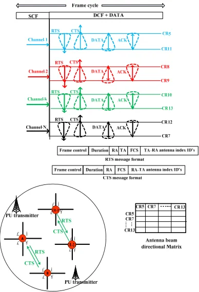
The operation of Distributed Co-ordination Function (DCF) is same as multi-channel MAC based DCF, i.e., DATA transmission succeeds with random Back-off algorithm [21]. Antenna index number of sender-receiver pair is added in RTS and CTS message formats.
A1 2 3B4 1 2
3A4 A1 2
CR-5
A1
2
3 4
CR-11
3 4
Figure 6. Random access based cognitive DCF operation.
Vector (NAV) in corresponding antenna directions during data transmission. The DCRequest and DCResponse in SCF operation helps to find collision free data channel for directional data transmission. With this, channel rendezvous delays and channel access contentions get reduced during DCF period. Whenever, the transmitter wants to communicate with destination at MAC layer, it run random back-off algorithm to contend the legitimate channel for data transmission. Since, cognitive radio networks operate on dynamic opportunistic multi-channels; it is very difficult to contend data channel without knowing neighbour PCL list and node synchronization. To solve this, channel for DCF operation is contended during SCF period with DCRequest and DCResponse messages. In DCF period, transmitter-receiver pair will tune to common data channel that is selected during SCF period. With this, multi-channel hidden terminal packet drops gets minimized and channel
rendezvous delays gets reduced. Moreover,
DCRequest/DCResponse help to select multiple directional data channels that helps to efficiently utilize the spatial spectrum and enhance the performance of CR-MAC protocol. Once directional RTS and CTS messages are broadcasted, node will initiate its data transmission and wait for acknowledgment in directional antenna (see Figure.6). Furthermore, nodes within the network will broadcast its application data in their selected legitimate channels. With directional antennas, link aggregate throughput gets enhanced with minimal channel contention delays. In addition, data transmission with directional antennas helps to minimize node and network energy consumption with interference suppression.
3.3 Packet Buffering for Spectrum handover
In general, normal and priority data packets in traditional ad-hoc networks are transmitted through unlicensed 2.4 GHz or 5 GHz ISM spectrum band. This clearly shows that there is no concept of spectrum handover and PU activity in existing static ad-hoc networks. But, dynamic spectrum access based CR ad-hoc networks introduce a selection of licensed PU free control and data channel for CR communication. With this, new packet drops with spectrum mobility exist whenever, PU activity occurs in between source and destination CR communication. In addition, spectrum mobility can occur due to current CR communication channel degradation. At MAC layer in traditional ad-hoc networks, node mobility is identified through the re-transmissions of RTS/CTS messages within Time to Live (TTL) period. When node won’t reply CTS message within TTL time, then sender thinks that destination is not within the transmission range of sender. Subsequently, it identifies another next hop neighbour to continue its communication with network. But, node location will not be changed during spectrum handover in cognitive radio networks. This shows that communication with the same destination is possible with different opportunistic spectrum band. Hence, packet buffering mechanism at link level helps to buffer the in-flight packet
EAI
European Alliance for Innovation6
drops and continue its communication in another selected PU free channel. To achieve this, we add a separate packet buffer for each and every spectrum handover node at sender link layer to store the in-flight packet drops that is shown in Figure.7.
Figure 7. Overview of spectrum handover packet
buffering.
In this paper, we use Random Early Detection (RED) buffer to store and forward the CR spectrum handover packets. At receiver, two RED buffers namely normal Input and priority buffers are used to avoid buffer overflow packet drops. This is because the receiver RED queue may be congested with other connections. In addition, the priority buffer at receiver will be activated only when the average queue length of the receiver input RED buffer is greater than maximum threshold level. The RED buffer characteristics like average queue length (Avg que_ length), minimum threshold (
min
Thresold ) and maximum threshold (Thresoldmax) are
used to check the congestion level of the RED buffer in receiver side. During link channel re-construction, the current status of the input RED buffer of receiver will be
transmitted to sender CR node. When
min
_ length
Avg que Thresold then the in-flight packets from
sender to receiver will be transmitted through Input RED buffer. At this case, priority bit and markers are disabled at
sender radio interface. When
_
min length max
Thresold Avg que Thresold then the
buffered in-flight packets from sender CR node are transmitted with higher priority. But, higher priority packets are also transmitted in input RED buffer at receiver. In last case, packets will be transmitted in priority buffer when
max
_ length
Avg que Thresold . In our work, priority buffer
is only used in final case to efficiently utilize the hardware and radio resources. With this, in-flight spectrum handover packet drops gets reduced and control overhead gets minimized at sender CR node. In addition, channel-link reconstruction time is relatively fast when compared with In-band and out-of-band CCC based CR-MAC. This is
because each and every CR node will have complete network channel information during SCF period.
3.4 Protection of hidden PU receivers
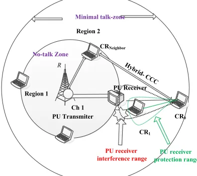
Opportunistic licensed channel access in cognitive radio introduces a new kind of packet drops due to interference with edge PU receivers at no-talk zone. Since traditional networks operate on unlicensed ISM bands, there is no concept of interference with PU receivers. FCC has released the TV white space for opportunistic secondary access based cognitive data transmission. Since TV receivers are uni-directional, it is very difficult to identify the existence of TV receivers at no-talk zone. CR nodes within the minimal-talk zone can communicate with same channel of no-talk zone without interfering no-talk zone coverage area. But, nodes within the minimal talk-zone can be the source of interference to PU receivers at the edge of no-talk zone. The scenario where CR node can interfere with PU receiver is shown in Figure.8.
Region 2
R
Ch 1 PU Transmiter
PU Receiver
CR0 CRNeighbor
Hy brid- CC
C
PU receiver protection range
PU receiver interference range
CR1
No-talk Zone
Minimal talk-zone
Region 1
Figure 8. PU receiver interference scenario at no-talk zone.
Normally, CR to PU receiver interference can occur due to CR node mobility (see Figure.2) and CR spectrum mobility (see Figure.3). To overcome this problem, it is significant control the CR transmit power through the location information of PU transmitter and its no-talk zone coverage area. To achieve, this work introduce an adaptive power control algorithm where at least one CR node is assumed to be aware of the location information of PU transmitter, its transmitting power and its no-talk coverage range. From Figure.5, CRneighbor is located in the no-talk zone of PU
transmitter. During control message exchange, CRneighbour
can update its PU transmitter characteristics through hybrid control channel in SCF period. Subsequently, CR transmitter (CR0) will calculate the close-but-not-overlap
power to its receiver. The detailed analytical explanation for CBO power estimation is explained in [22]. Whenever CR communication is not possible with minimum CBO power level, then it has find out another PU free channel to continue its communication or need to wait for next control slot to and contend and communicate in another PU free
EAI
European Alliance for Innovation7
channel. With this, packet drops due to PU receiver interference gets reduced. This helps to minimize the control overhead and enhance the performance of primary and secondary networks.
3.5 Directional DCF energy conservation
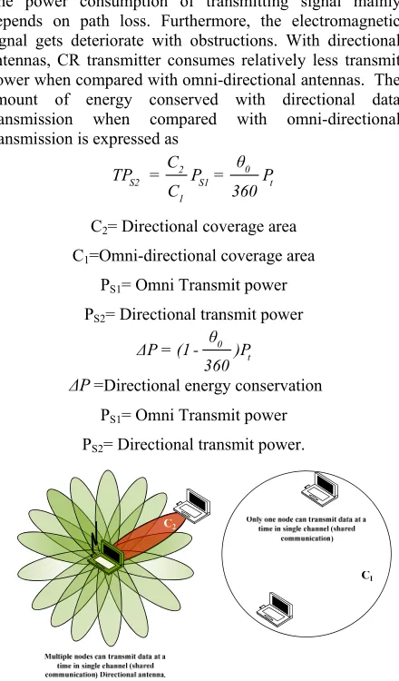
The power consumption of transmitting signal mainly depends on path loss. Furthermore, the electromagnetic signal gets deteriorate with obstructions. With directional antennas, CR transmitter consumes relatively less transmit power when compared with omni-directional antennas. The amount of energy conserved with directional data transmission when compared with omni-directional transmission is expressed as
0 2
S2 S1 t
1
θ
C
TP = P = P
C 360
C2= Directional coverage area
C1=Omni-directional coverage area
PS1= Omni Transmit power
PS2= Directional transmit power
0 t θ ΔP = (1 - )P
360
ΔP=Directional energy conservation PS1= Omni Transmit power
PS2= Directional transmit power.
Figure 9. Directional DCF data energy conservation.
Figure.9 shows the data transmission scenario with directional and omni-directional antennas. The amount of node energy conservation depends on antenna beam width. This depicts that the directional data transmission can conserve ∆P power at each CR node when compared with omni-directional data transmission. Moreover, spatial spectrum is efficiently utilized and node achievable throughput gets increased due to reduced channel waiting time.
4. Simulation Results
Cognitive radio network simulator (NS-2.31) [23-25] is used to implement analyze the performance of proposed
Interference aware hybrid-CCC based Cognitive MAC protocol with directional antennas. In this work, extension of multi-channel directional MAC protocol with legitimate user implementation in 400 MHz TVWS [26] (8-MHz channel) is used for analysing aggregate network throughput and link delays. Aggregate network throughput and link delays are calculated with data rate and compared with other existing solutions. In addition, the link throughput and delay of proposed hybrid CR-MAC with directional antennas is checked with the variation of channel numbers and PU transmitter active probability. In this work, we initially consider the available channels numbers as 5 with a data rate of 2 Mbps each. Later, channel numbers are varied from 5 to 10 to check the maximum achievable aggregate throughput. The total numbers of 1-hop CR nodes are considered as 100 whereas the total number of PU transmitters are considered as 10 in 400 MHz TV spectrum band. Number of link connections (flows) is considered as 50 with 1024 byte application data. During the start of simulation, 1-PU transmitter is active within the cognitive communication. Route changes randomly occur with node and spectrum mobility during the simulation. Channel switching occurs during the simulation period due to
dynamic PU-transmitter active in current CR
communication range. At this time, CR nodes will have increased control overhead during channel-link re-construction period. The total simulation time to run proposed hybrid CR-MAC is considered as 50 sec. The initial directional transmission of control and data packets (DCF) starts at 9th Sec with single PU transmitter active.
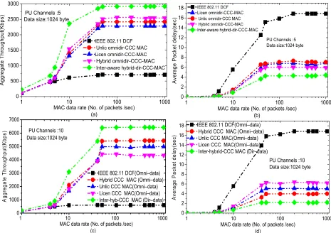
During the simulation period, remaining PU transmitters are randomly active. This helps to check the control overhead of the proposed Cognitive MAC protocols and compare with existing solutions. Figure.10 explains about the aggregate network throughput and average link delays with data rate. Subsequently, the throughput and link delays are compared with traditional IEEE 802.11 DCF and existing In-band and out-of-band CCC based Cognitive MAC protocols. Figure.10 (a) shows the aggregate throughput with data rate for 1024 byte data in 5-PU free channels. As shown in Figure.10(a), the proposed hybrid CCC based cognitive MAC with directional antennas has enhanced aggregate throughput when compared with other existing solutions. This is because of tight node synchronization and reduced hidden terminal packet drops with hybrid control channel. In addition, directional RTS/CTS and data transmission results in increased spatial reuse. Subsequently, more number of concurrent data transmissions is allowed in existing channels. Furthermore, channel waiting time gets decreased and probability of channel contentions gets minimized with directional antennas. The second highest aggregate throughput is achieved for hybrid CCC-CR-MAC with Omni-directional antennas. Since, the probability of channel availability and concurrent transmissions in Omni-directional hybrid CR-MAC is less, the achievable throughput in Omni-directional hybrid-CCC based CR MAC is relatively less when compared with directional-hybrid-CCC-CR-MAC protocol. The third highest aggregate throughput is achieved with
EAI
European Alliance for Innovationsaturated unlicensed CCC (2.4 GHz ISM)-based CR-MAC protocol. This may be because of increased collisions due to
interference with other technologies and control channel saturation overflows. The lowest aggregate throughput gets achieved for IEEE 802.11 DCF. This is because of increased channel access contention and longer channel access delays due to operation in single non-overlapping channel. Figure.10(b) shows the average packet delay with respect to data rate in 5 PU free multi-channels. The average packet delay for proposed hybrid-CCC-CR-MAC with directional antennas is less when compared with existing Omni-directional CCC based cognitive MAC protocols and IEEE 802.11 DCF. This is because of high probability of communication channel availability and reduced packet drops due to node mobility and spectrum mobility. In addition, packet buffering helps to avoid the in-flight packet drops during spectrum handover. In-band and out-of-band Omni-directional CCC based multi-channel CR-MAC has relatively lower packet delays in comparison with single non-overlapping based IEEE 802.11 DCF. Figure.10(c) explains about the aggregate throughput with respect to data rate in 10 PU-free channels. With increased number of available PU free channels, it is obvious that network load gets shared in different non-overlapping channels. This
helps to avoid longer channel access delays and channel contention packet drops. In addition, packet drops due to
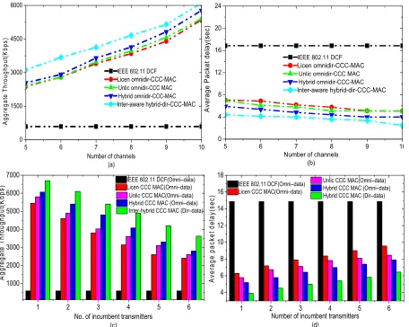
increased collision overhead get reduced for more number of available PU free channels. Thus, aggregate throughput for 10-PU free channels is high when compared with 5-PU free channels (see Figure. 10(a)). Moreover, aggregate throughput for directional antenna based hybrid CR-MAC is better than existing Omni-directional based CCC-CR-MAC protocols. Figure.10 (d) explains about the average packet delays with data rate in 10 PU-free channels. In general, the average packet delay in between source-destination pair depends on packet size and data channel availability. With 10 PU free channels, the average delay in hybrid CCC-CR with directional antenna is less when compared with In-band, out-of-band CCC-CR-MAC and traditional IEEE 802.11 DCF. Figure.11 explains about the aggregate throughput and average packet delay with respect to variation of PU free channels and PU transmitters. Figure. 11(a) explains about the aggregate throughput with increased number of available data channels. It is clear that aggregate throughput gets increased with more number of available data channels. Furthermore, enhanced spectrum efficiency for directional antennas helps to achieve more aggregate throughput in comparison with Omni-directional
1 10 100 1000
0 500 1000 1500 2000 2500 3000
IEEE 802.11 DCF Unlic omnidir-CCC MAC Licen omnidir-CCC-MAC Hybrid omnidir-CCC-MAC Inter-aware hybrid-dir-CCC-MAC A gg re gat e T hr ough put (K bps)
MAC data rate (No. of packets /sec) (a)
PU Channels :5 Data size:1024 byte
1 10 100 1000
0 2 4 6 8 10 12 14 16
18 IEEE 802.11 DCF Licen omnidir-CCC-MAC Unlic omnidir-CCC MAC Hybrid omnidir-CCC-MAC Inter-aware hybrid-dir-CCC-MAC
PU Channels :5 Data size:1024 byte
A ver a ge P acket d el ay( se c)
MAC data rate (No. of packets /sec) (b)
1 10 100 1000
0 1000 2000 3000 4000 5000 6000 7000
MAC data rate (No. of packets /sec) (c)
Data size:1024 byte PU Channels :10
IEEE 802.11 DCF(Omni–data) Hybrid CCC MAC (Omni–data) Unlic CCC MAC(Omni–data) Licen CCC MAC(Omni–data) Inter-hyb-CCC MAC (Dir–data)
A ggr ega te T hr ou ghput (K bp s)
1 10 100 1000
0 2 4 6 8 10 12 14 16 18
PU Channels :10 Data size:1024 byte IEEE 802.11 DCF(Omni–data)
Hybrid CCC MAC (Omni–data) Unlic CCC MAC(Omni–data) Licen CCC MAC(Omni–data) Inter-hybrid-CCC MAC (Dir–data)
A ver ag e P ac ket del ay (s ec )
MAC data rate (No. of packets /sec) (d)
9
Cognitive MAC protocols. Figure. 11 (b) explains about the average packet delay with respect to variation of available
PU free channels. The delay for IEEE 802.11 DCF is constant due to single non-overlapping data operation. The average packet delay gets reduced with more number of available data channels. This is due to reduced channel contention delay and reduced hidden terminal packet drops. Figure.11 (c) shows the aggregate throughput with the variation of PU activity in current CR network. At first, only 1-PU transmitter is active in 5-PU free channels. CR nodes can make use of 4 channels for data transmission. During 2-PU transmitter active, only 3 non-overlapping PU free channels are available for data transmission. This shows that frequent link re-constructions and increased control overhead with more number of active PU transmitters results in less achievable aggregate throughput. But with directional antennas, reduced directional node transmit power helps to communicate with its next-hop neighbours without interfering PU transmissions. With this, directional hybrid CCC-CR-MAC can achieve better aggregate throughput when compared with Omni-directional based In-band and out-of-band CCC-CR-MAC protocols. Moreover, directional spectrum reuse helps to
minimize interference probability with neighbour hidden terminals. Figure. 11(d) explains about the average packet
delay with respect to PU transmitter active. Average packet delay gets increased with more number of active PU transmitters in current CR communication.
5. Conclusion
Aggregate network throughput, link delays and performance of Cognitive-MAC protocol directly depends on interference due to multi-channel PU and CR hidden terminal. Moreover, control channel design plays an significant role in avoiding hidden-terminals through tight node synchronization during cognitive control message exchange. Existing literature propose In-band and out-of-band Common Control Channel (CCC) based Cognitive
MAC protocol for network connectivity, node
synchronization and cognitive control message exchange. But, the drawbacks like multi-channel hidden terminal, higher cognitive control overhead, longer channel access delays and edge PU receiver packet drops are not efficiently resolved. To achieve this, Interference aware hybrid
CCC-5 6 7 8 9 10
0 1500 3000 4500 6000
IEEE 802.11 DCF Licen omnidir-CCC-MAC Unlic omnidir-CCC MAC Hybrid omnidir-CCC-MAC Inter-aware hybrid-dir-CCC-MAC
A
g
gr
eg
at
e
T
h
ro
ug
hp
ut
(K
bp
s)
Number of channels (a)
5 6 7 8 9 10
0 4 8 12 16 20 24
IEEE 802.11 DCF Licen omnidir-CCC-MAC Unlic omnidir-CCC MAC Hybrid omnidir-CCC-MAC Inter-aware hybrid-dir-CCC-MAC
A
ver
age
P
ac
ket
d
el
ay
(s
ec)
Number of channels (b)
1 2 3 4 5 6
1000 2000 3000 4000 5000 6000 7000
Unlic CCC MAC(Omni–data) Hybrid CCC MAC (Omni–data) Inter-hybrid CCC MAC (Dir–data) IEEE 802.11 DCF(Omni–data) Licen CCC MAC(Omni–data)
A
gg
reg
at
e
T
hr
oug
hput
(K
bp
s)
No. of incumbent transmitters (c)
1 2 3 4 5 6
4 6 8 10 12 14 16 18
Unlic CCC MAC(Omni–data) Hybrid CCC MAC (Omni–data) Hybrid CCC MAC (Dir–data) IEEE 802.11 DCF(Omni–data)
Licen CCC MAC(Omni–data)
A
ver
a
ge
pac
ket
del
ay
(s
ec
)
Number of incumbent transmitters (d)
Figure 11. Aggregate throughput and average link delays calculation with number of channels and PU transmitters.
EAI
European Alliancefor Innovation EAI Endorsed Transactions
CR-MAC with directional antennas are proposed in this paper. In our work, slotted-TDMA based Omni-directional cognitive control broadcast and directional DCF based data transmission is proposed. With this, achievable aggregate throughput gets enhanced with reduced average link delays. This is because of efficient directional spatial spectrum re-use and minimized control overhead due to hidden terminal packet drops.
Acknowledgements.
This research was supported by the MSIP (Ministry of Science, ICT and Future Planning), Korea, under the ITRC (Information Technology Research Center) support program (IITP-2015-H8501-15-1019) supervised by the IITP (Institute for Information & communications Technology Promotion).
References
[1] S. H. Chun and R. J. La, “Secondary Spectrum Trading—Auction-Based Framework for Spectrum Allocation and Profit Sharing,” IEEE/ACM Trans. Netw., vol. 21, no. 1, pp. 176-189, 2013.
[2] Ian F Akyildiz, Won-Yeol Lee, Kaushik R Chowdhury. CRAHNs: Cognitive radio ad hoc networks [J]. Ad Hoc Networks, 2009, 7(5): 810-836.
[3] Tragos, E.Z.; Zeadally, S.; Fragkiadakis, A.G.; Siris, V.A., "Spectrum Assignment in Cognitive Radio Networks: A Comprehensive Survey," Communications Surveys & Tutorials, IEEE , vol.15, no.3, pp.1108,1135, Third Quarter 2013.
[4] T. Baykas, M. Kasslin, M. Cumming, H. Kang, J. Kwak, R. Paine, A. Rezni, R. Saeed and S.J. Shellhammer, “Developing a standard for TV white space coexistence: technical challenges and solution approaches,” IEEE Wireless Commun., vol. 19, no. 1, pp. 10-22, 2012. [5] S. Sengupta and K. P. Subbalakshmi, “Open research
issues in multi-hop cognitive radio networks,” IEEE Commun. Mag., vol. 51, no. 4, pp. 168-176, 2013. [6] Gavrilovska, L.; Denkovski, D.; Rakovic, V.;
Angjelichinoski, M., "Medium Access Control Protocols in Cognitive Radio Networks: Overview and General Classification," Communications Surveys & Tutorials, IEEE , vol.16, no.4, pp.2092,2124, Fourthquarter 2014. [7] B. F. Lo, “A survey of common control channel design
in cognitive radio networks”, Elsevier J. of Physical Commun., vol. 4, no. 1, pp. 26-39, 2011.
[8] L A DaSilva, I Guerreiro. Sequence-based rendezvous for dynamic spectrum access. IEEE Symposium on New Frontiers in Dynamic Spectrum Access Networks [C]. Chicago, USA, 2008: 1–7.
[9] Y R Kondareddy, P Agrawal. Synchronized MAC protocol for multihop cognitive radio networks. IEEE International Conference on Communications [C]. Beijing, China, 2008 : 3198–3202.
[10] C. Cormio and K. R. Chowdhury, “Common control channel design for cognitive radio wireless ad hoc networks using adaptive frequency hopping” Elsevier J. of Ad Hoc Netw., vol. 8, no. 4, pp. 430-438, 2010. [11] Yanchao Xu, Chengyu Wu, Chen He, Lingge Jiang. A
cluster-based energy efficient MAC protocol for
multi-hop cognitive radio sensor networks. IEEE Conference on Global Telecommunications [C]. Anaheim, CA, 2012: 537-542.
[12] B. F. Lo, I. F. Akyildiz and A. M. Al-Dhelaan, “Efficient Recovery Control Channel Design in Cognitive Radio Ad Hoc Networks,” IEEE Trans. Veh. Technol., vol. 59, no. 9, pp. 4513-4526, 2010.
[13] J. Jia, Q. Zhang and X. Shen, “HC-MAC: A Hardware-Constrained Cognitive MAC for Efficient Spectrum Management,” IEEE J. Sel. Areas in Commun., vol. 26, no. 1, pp. 106-117, 2008.
[14] A. Nasipuri, S. Ye, J. You and R. E. Hiromoto, “A MAC protocol for mobile ad hoc networks using directional antennas,” in Wireless Commun. Netw. Conf., 2000, pp. 1214-1219.
[15] A Motamedi, A Bahai. MAC protocol design for spectrum-agile wireless networks: stochastic control approach. IEEE International Symposium on New Frontiers in Dynamic Spectrum Access Networks [C]. Dublin, 2007: 448–451.
[16] H Su, X Zhang. Opportunistic MAC protocols for cognitive radio based wireless networks. Annual Conference on Information Sciences and Systems [C], Baltimore, USA, 2007: 363–368.
[17] R.Tandra, S.M. Mishra and A. Sahai , "What is a Spectrum Hole and What Does it Take to Recognize One?," in Proc. of IEEE, vol. 97, no.5, pp.824-848, 2009.
[18] P. Djukic and P. Mohapatra, "Soft-TDMAC: A Software-Based 802.11 Overlay TDMA MAC with Microsecond Synchronization," IEEE Trans. Mobile Comput., vol. 11, no.3, pp.478-491, 2012.
[19] S. Anamalamudi; M. Jin, “Low rate common control channel based AODV routing protocol for cognitive radio ad-hoc networks,” in Proc. 5th IEEE Int. Conf. Ubiquitous and Future Netw., 2013, pp.625-630. [20] Satish Anamalamudi and Minglu Jin, " Hybrid Common
Control Channel Based MAC Protocol for Cognitive Radio Ad-Hoc Networks," Int. J. of Infor. Electron. Eng. vol. 4, no. 3, pp. 216-224, 2014.
[21] C. Ye, Y. Li and A. Reznik, "Performance Analysis of Exponential Increase Exponential Decrease Back-Off Algorithm," in Proc. IEEE Int Conf. Global Telecomm., 2010, pp.1-6.
[22] S. Anamalamudi, M. Jin and J. M. Kim, “Interference-Aware Hybrid CCC-based MAC Protocol for Cognitive Radio Ad Hoc Networks," IEEE-ICC-Workshop on Advances in Software Defined and Context Aware Cognitive Networks, 2015.
[23] VINT Group. \UCB/LBNL/VINT network simulator ns (version 2)[online], Available: http://www.isi.edu/nsnam/ns/
[24] The CMU Monarch Project. \Wireless and Mobility Extension to ns[online], Available:http://www.monarch.cs.rice.edu/
[25] J. Zhong, “Development of NS-2 Based Cognitive Radio Cognitive Network Simulator”, MS Thesis, Michigan Technological University, 2009.