5127
Dr.M.Kavitha, T.Dinesh Kumar, Dr.A.Gayathri,
V.Koushick
Abstract—A simple rectangular microstrip feed antenna is proposed for 5G communication. The proposed structure has 7.9 x 14.71 x 1.6 mm dimension and the substrate used in the design is FR-4. The antenna has the operating band from 27.67 GHz to 28.31 GHz band. The reflection coefficient is above -14dB. The simulated results s11, VSWR, surface current and radiation pattern are used to validate the proposed structure is the right choice for 5G communication. Further the radiation pattern shows a stable performance in the operating band.
Index Terms—5G Communication, Rectangular Patch, Microstrip, Array
—————————— ——————————
1
INTRODUCTION
The microstrip based patch antenna is also called as printed antenna since the radiating element is printed on front side of the substrate and ground is printed on the back side. The radiating element and the ground is generally made up of the conducting element such as copper, gold and silver. The size and shape of the radiating element may vary based on its frequency of application. Microstrip patch antenna has found its application in various fields such as
RFID, GPS [1], V2V communication, Satellite
communication, Radar [2] and Remote sensing but one of the major drawbacks with respect to the microstrip patch antenna is losses due to dielectric and surface waves. Because of this loss the microstrip patch antenna is able to achieve the narrow bandwidth and lower gain. The above-mentioned drawbacks are overcome with the help of various techniques like feeding technique, meandering, metamaterials [3] and EBG. Low cost and profile of the microstrip antenna made it more useful and compatible in MMIC fabrication [4,5]. Metamaterial [6,7] is an artificial material with negative permittivity and permeability characteristics, which is incorporated with microstrip
————————————————
1
Dr.M.Kavitha, Professor, Department of ECE, Ramakrishnan College of Technology, Trichy, Tamilnadu India.
2
T.Dinesh kumar ,Assistant Professor, Department of ECE, Kongunadu College of Engineering and Technology, Trichy, Tamilnadu India.
3
DrA.Gayathri, Assitant Professor, Scholl of information technology & Engineering,VIT ,Vellore, India
4
V.Koushik, Assistant Professor, Department of ECE, Saranathan College of Engineering, Tamilnadu, India.
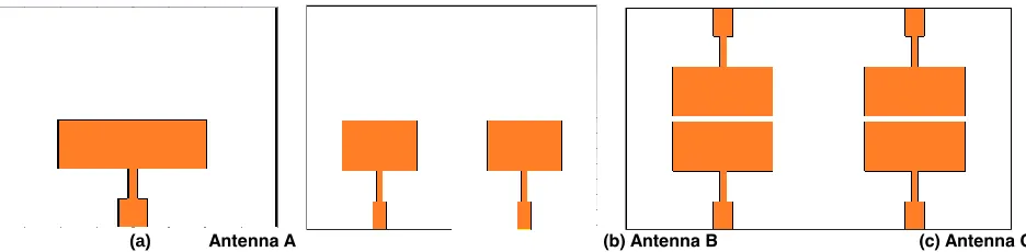
patch antenna to enhance the gain, bandwidth and other prime parameters Many researches achieve the wider bandwidth by changing the patch shapes. But the gain can be improved with the help of array configuration[8-12].The simple microstrip patch antenna at 28GHz [8] is chosen ae the seed design of the proposed antenna. In order to achieve proper impedance matching the quarter wave transformer with 87.26 Ω characteristic impedance is employed between the antenna and feed line. λ/4 is used for the length of the transmission line with width to 50 Ω. Figure 1 clearly depicts the evolution of the proposed antenna structure. The proposed antenna has three stages of evolution. Antenna A is a simple rectangular patch antenna with microstrip feed resonating at 28 GHz with the help of quarter wave transmission line. Antenna B is the 1x2 antenna array with antenna A as array element and finally the Antenna C is designed as 2x2 antenna array to achieve good gain with antenna A as array element. The Figure 1 (d) shows the parameter of the proposed antenna A and table 1 give the parameter values.[13-16]
2
PROPOSED
ANTENNA
DESIGN
A. SINGLE ELEMENT
The antenna A is the initial design for the proposed antenna at 28 GHz. It is a simple rectangular microstrip feed patch antenna with quarter wave transformer feed line. The entire structure is designed on a FR4 substrate with radiating element in one end and full ground on the other side of the substrate. The height of the substrate is 1.6 mm with 7.9mm and 14.7 as its width and length respectively. The length and width of the radiating element is 3.3 mm and 4.4 mm respectively with the thickness of 0.035 mm.
(d) Antenna Parameters
Figure 1 Evolution of proposed antenna and its parameters Table 1 Parameter Values of Antenna A (all dmensions are in mm)
W L Wp Lp W1 Wf L1 Lf H T
7.9 14.7 4.1 3.3 0.31 0.78 1.9 3.9 1.6 0.035
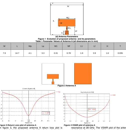
Figure 2 Antenna A
Figure 3 Return Loss plot of antenna A Figure 4 VSWR plot of antenna A
In figure 3, the proposed antenna A return loss plot is presented which clearly shows that the designed structure has an operating band from 27.55 GHz to 28.35 GHz with
resonance at 28 GHz. The VSWR plot of the antenna A is depicted in figure 4, from which we can observe that the value of the VSWR is less than 2 in the operating band.
Figure 5 Antenna A Radiation Pattern E plane and H plane
5129
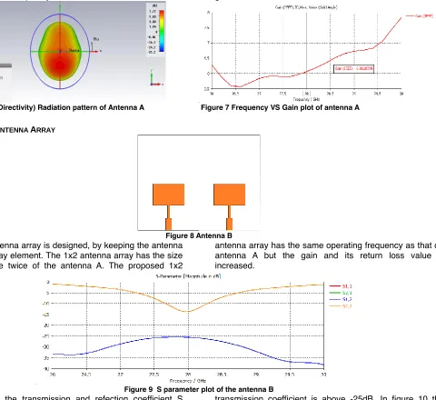
Figure 6 3D (Directivity) Radiation pattern of Antenna A Figure 7 Frequency VS Gain plot of antenna A
B 1X2ANTENNA ARRAY
Figure 8 Antenna B
The 1x2 antenna array is designed, by keeping the antenna A as the array element. The 1x2 antenna array has the size equal to the twice of the antenna A. The proposed 1x2
antenna array has the same operating frequency as that on antenna A but the gain and its return loss value is increased.
Figure 9 S parameter plot of the antenna B
In figure 9, the transmission and refection coefficient S parameters are plotted with respect to the frequency of the operation. From the figure it is observed that the simulated maximum return loss value is nearly -14.8 dB and the
transmission coefficient is above -25dB. In figure 10 the VSWR plot is presented, from that we can observe that the VSWR value is less than 2 in the operating band.
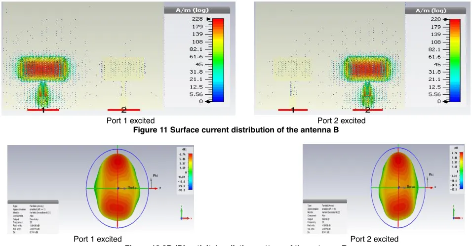
Port 1 excited Port 2 excited Figure 11 Surface current distribution of the antenna B
Port 1 excited Port 2 excited Figure 12 3D (Directivity) radiation pattern of the antenna B
In Figure 11 and 12, the surface current distribution and the 3D radiation patten of the proposed 1x2 antenna array when port 1 and port 2 is excited is presented. From the surface current distribution plot, we can observe that the maximum current is available in antenna element 1and antenna element 2 when port 1 and port 2 is excited respectively. The mutual coupling between the antenna
element 1 and antenna element 2 is very low, since the distance between the two element is choose to be half of the resonating wavelength. In Figure 13, the gain of the proposed 1x2 antenna array is plotted against the frequency. From which we can clearly observe that the gain is above 6.15 dBi in the entire operating band from 27.58 GHz to 28.35 GHz with resonating band at 28 GHz.
Figure 13 Gain plot of antenna B
C 2X2 ANTENNA ARRAY
Figure 14 Antenna C
The proposed 2x2 array is designed as shown in figure with the same dimension as that of antenna B. the only difference between antenna B and antenna C is antenna B has 2 elements and antenna C has 4 elements. The total size of the proposed antenna is 15.8 mm x 24.9 mm x 1.6 mm. By increasing the number of elements in the proposed structure from two to four impedance matching, bandwidth
5131 Figure 15 S parameter plot of the antenna C Figure 16 VSWR plot of the antenna C
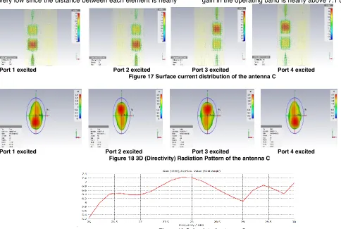
In figure 17, the surface current distribution of the proposed 2x2 antenna array when each port is excited separately is presented, from the figure we can observe that maximum current is distributed in the element corresponding to the exciting port. The mutual coupling between the element is very low since the distance between each element is nearly
equal to half of the resonating wavelength. In figure 18 the 3D radiation pattern of the proposed 2x2 antenna array is presented from which the maximum directivity is perpendicular to the antenna axis. The gain of the proposed antenna array is presented in figure 19 and the maximum gain in the operating band is nearly above 7.1 dBi
Port 1 excited Port 2 excited
Port 3 excited Port 4 excited Figure 17 Surface current distribution of the antenna C
Port 1 excited Port 2 excited
Port 3 excited Port 4 excited Figure 18 3D (Directivity) Radiation Pattern of the antenna C
Figure 19 Gain plot of antenna C
4
RESULT
AND
DISCUSSION
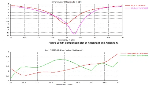
The proposed antenna has three evolution stages a simple rectangular patch antenna (Antenna A), 1x2 antenna array (Antenna B) and 2x2 antenna array (Antenna C). The Antenna A is a simple rectangular patch antenna fed with quarter wave transmission line in order to achieve the impedance matching. The proposed structure has an operating range from 27.55 GHz to 28.35 GHz with resonance at 28 GHz with -14.8 dB as maximum return loss. Then the second stage is designed with two element array which has the same operating range from 27.55 GHz to 28.35 GHz with resonance at 28 GHz with -15 dB as
Figure 20 S11 comparison plot of Antenna B and Antenna C
Figure 21 Gain comparison plot of Antenna B and Antenna C
5
CONCLUSION.
The proposed structure has three evolution stages. All the structure are designed with FR4 substrate for 28GHz 5G communication band. The antenna A is a simple microstrip feed patch antenna with the operating range from 27.55 GHz to 28.35 GHz. Antenna B is a 1x2 antenna array with same operating range as that of antenna A with slight impedance matching improvement and finally antenna C is 2x2 antenna array which has a wider bandwidth and higher gain with improve impedance matching as compared with the antenna A and B. The final proposed antenna C has a total size of 15.8 mm x 24.9 mm x 1.6 mm. Its operating range is from 27.58 GHz to 28.53 GHz with the maximum gain of 7.2 dBi in the operating band. And proposed structure has very low profile easily mounted on MMIC devices make it more suitable for the 5G communication.
REFERENCES
[1] Dr.S.Shanthi, Dr. T. Jayasankar, Prasad Jones Christydass, Dr. P. Maheswara Venkatesh (2019) "Wearable Textile Antenna For GPS Application ", International Journal of scientific and Technology Research, Vol. 8, No. 11, 3788-3791.
[2] S. Prasad Jones Christydass, N. Gunavathi .(2017) "Codirectional CSRR inspired printed antenna for locomotive short range radar”, ICICI.
[3] S. Prasad Jones Christydass, N. Gunavathi. (2017) "Design of CSRR loaded multiband slotted rectangular patch antenna", IEEE AEMC
[4] Wong, K.-L. (2002) “Compact Dual-Frequency and Dual-Polarized Microstrip Antennas, Compact and
[5] Sidhu, S. K. and Singh Sivia, J. (2015) ‘’Comparison of Different Types of Microstrip Patch Antennas’’, International Journal of Computer Applications, (Icaet), pp. 975–8887.
[6] Prasad Jones Christydass and Pranit Jeba Samuel, (2019) "Metamaterial Inspired Slotted Rectangular Patch Antenna for Multiband Operation ", Biosc. Biotech. Res. Comm, Special Issue, Vol 12, No (6), pp 57-62.
[7] Prasad Jones Christydass and Manjunathan, (2019) "Pentagonal Ring Slot Antenna with SRR for Tri-Band Operation“, Biosc. Biotech. Res. Comm, Special Issue, Vol 12, No(6), pp 26-32.
[8] A Ali Nazar, R Jayabharath, MD Udayakumar “An ANFIS
Based Advanced MPPT Control of a Wind-Solar Hybrid Power Generation System,” international review of modelling and simulations. vol..7, no. 4, pp. 638–643, Jul. 2014.
[9] Dheeraj Mungur & Shankar Duraikannan ,(2018) ‘‘Microstrip Patch Antenna at 28 GHz for 5G Applications’’, Journal of Science Technology Engineering and Management – Advanced Research and Innovation, Volume 1, Issue 1, pp 20 – 22.
[10]V Venkatesh, A Nazar Ali,, R Jaiganesh. V indiragandhi [2019]
, “Extraction and conversion of exhaust heat from automobile engine in to electrical energy Energy”, IOP Conference Series: Materials Science and Engineering, vol. 23.
5133 pp.7489-7496
[13]A.Nazar Ali and R. Jayabharath. "Performance Enhancement of Hybrid Wind/Photo Voltaic System Using Z Source Inverter with Cuk-sepic Fused Converter." Research Journal of Applied Sciences, Engineering and Technology7.19 (2014): 3964-3970.
[14]K. Premkumar and B.V. Manikandan, “Stability and Performance Analysis of ANFIS Tuned PID Based Speed Controller for Brushless DC Motor,” in CURR SIGNAL TRANSD T, vol.13, no.1, 2018, pp. 19-30. [15]Premkumar et al. (2015), GA-PSO optimized online
ANFIS based speed controller for Brushless DC motor, Journal of Intelligent & Fuzzy Systems, 28, 6, pages.2839-2850.
[16]K Premkumar et al. (2018), Novel bacterial foraging-based ANFIS for speed control of matrix converter-fed industrial BLDC motors operated under low speed and high torque, Neural Computing and Applications, 29, 12, pages.1411–1434
[17]Premkumar, Kamaraj et al. (2018), Antlion Algorithm Optimized Fuzzy PID Supervised On-line Recurrent Fuzzy Neural Network Based Controller for Brushless DC Motor, Electric Power Components and Systems, 45, 20, pages.2304-2317.
[18]Sabarish, P., Sankara Subramanian, A.T., Gayathri, A., Anton Amala Praveen, A. C.[2019] “A Novel wearable therapeutic aid with intelligent information processing systems” IOP conference series: Materials science and engineering .
[19]AT Sankara Subramanian, P Sabarish, A Nazar Ali. “A power factor correction based canonical switching cell converter for VSI fed BLDC motor by using voltage follower technique”IEEE International Conference on Electrical, Instrumentation and Communication Engineering (ICEICE), pp.1-8, 2017.