Volume-6 Issue-4
International Journal of Intellectual Advancements
and Research in Engineering Computations
Design dual converter interfaced microcontroller application
1
Mr. Suresh Palaka,
2Mr. N Ravindar,
3Ms. T Divya
1
DEAN, HIT, IInd Shift Polytechnic college, Hyderabad. 2
Assistant Professor, ECE Department, HITS, Hyderabad. 3
Assistant Professor, ECE Department, HITS, Hyderabad.
ABSTRACT
Transducer is an device that convert one form of energy into an other form of energy. In Embedded system designs, these transducers plays key role about control the applications. Analog quantities are converts into binary form and then make digitized. Similarly digital data processed to make analog output. The two methods use 8051 microcontrollers for control applications separately. Now a new design is proposed that a single microcontroller is interfaced to both ADC & DAC at an instance. It is helpful to many mechanical control applications like refrigeration and air-conditioning. As an example working model for air conditioner is explained.
INTRODUCTION
Before to know how it is interface the both ADC and DAC into microcontroller, it is good to introduce about conversion processes of both methods. In ADC, a procedure starts with input data is sampled, quantized and then convert into binary form with decoding process. In DAC, the decimal input data initially processes to binary form and then output observed as analog. The following concepts are briefly explained about both ADC and DAC.
Working principles of air conditioner
Ambient temperature affects directly working performance of persons. Hot or cold environment do certainly not sustain higher working efficiency and thermal comfort. Outdoor climate may not be convenient for working condition. However, indoor climate can be adjusted according to personal preferences. Generally, air conditioners are used for these purposes. The amount of cooling or heating indoor varies depending on outdoor and indoor temperatures. The cooling and heating can be achieved by an air conditioner. When the air conditioner is on, the compressor operates at a high
speed in order to cool, or heat the room quickly. As the room temperature is equal to the reference temperature, the compressor slows down, maintaining a constant temperature and saving energy.
ADC &DAC
A microcontroller is a chip that combines all the components of a microprocessor-based system with an integrated circuit. Microcontrollers are used as digital to analog to converter and analog to digital converter. Although analog to digital conversion (ADC) applications are very common, digital to analog conversion (DAC) applications are not so common but DAC is used in driving various electronic devices, sensor circuits and LED driving circuits. The aim of this project is to generation of PWM signal, filter design and the regulation process of DAC.
This study concerns an implementation of DAC for Microcontroller. This experiment aims to teach PWM signal generation, digital analog conversion and filter design in the direction of programming and electronic information that learns. It is expected to generate the PWM signal by a microcontroller, convert this signal to analog using
a filter, and design the required ripple filter circuit. Combining microcontroller programming with analog circuit design is expected to improve student’s expertise and motivation.
At first, it is explained how to generate PWM signal by using microcontroller. Then, technical information was given about the required filter designs and the signal values converted to digital were shown on the liquid crystal display (LCD).
Pulse Width Modulation (PWM)
PWM is a technique for obtaining the analog signal desired to be produced at the output by
controlling the widths of the pulses. The application of PWM technology is becoming increasingly widespread. PWM method is widely used in areas such as switching Mode power supplies, telecommunication, applications and power circuits. In this experiment, the PWM signal generated by the microcontroller is used as digital data. When PWM signal is generated, two components are considered: duty cycle and frequency as shown in fig 1.
Fig.1 Duty Cycle Examples
The duty cycle determines the ratio of time while the PWM signal is high to the period of the signal. Frequency is simple the frequency of the signal.
Low-pass and Ripple Filter Design
An electrical filter is a circuit that can be designed to reshape or reject all undesired frequencies of an electrical signal to transmit signals sought by the circuit designer. In this design a low pass filter and a ripple filter were used. Filter design is shown in the figure.2. The low pass filter consisting of diode, capacitor and internal resistance of the system is used to find the
Fig. 2 Filter Circuits
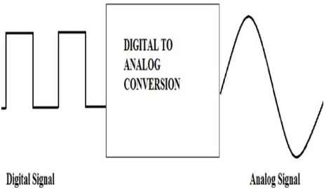
Digital to Analog Conversion
Digital information such as 1 and 0 is referred to as digital analog conversions in circuits or integrated circuits that produce currents or voltages at different values according to the change in input
values at the input and output, and this conversion is also called digital to analog conversion. The digital to analog signal conversion is shown in figure 3.
Fig.3 Digital To Analog Conversion
In this design, a microcontroller generates digital signals using pulse width modulation (PWM). The PWM signal produced to convert to analog signal has two important components; duty cycle and frequency. There is a direct proportion between the output voltage and the duty cycle. The
output voltage is controlled by changing the duty cycle in the experimental setup. The PWM signals whose duty cycle was changed were observed with an oscilloscope. The out duty cycle signal is shown in the figure 4.
First of all, use the Microcontroller program to write the microcontroller code to be used in generating the appropriate PWM signal. When writing the code, the student is expected to know how to start the PWM module in the PIC Clicker demo board, set up the correct pin connections and adjust the duty cycle and make the LCD connections to display duty cycle.
After generating the PWM signal, students design the circuit that will make the necessary adjustments that will convert this signal to digital. They set up a low-pass filter circuit using a diode and a capacitor. This filter blocks the passage of high frequencies in the signal and makes the signal smoother. But this correction is not enough to create a complete digital signal. They set up a ripple filter circuit using an inductance and a capacitor to eliminate the ripples observed on the signal. In this way, a nearly flat digital signal is obtained. After that digital to analog conversion is completed. They observe the filter output through an oscilloscope and record their observations.
PROBLEM
According to the various advancements, high end microcontrollers supports to design interfacing ADC and DAC Like refrigerator design with microcontroller. The proposed design previously not supported with low end controllers. Now it is proposed that interfacing both converters as Input and output to an unique microcontroller.
As an example 8051is used to design proposed work. This work may helpful to develop low cost control designs like refrigerator.
PROPOSED HARDWARE DESIGN
The whole system for hardware design block diagram is illustrated in Figure 5. In this paper, the control card for air conditioner is constructed for hardware design based on 8051. Microcontroller programming is considered for software implementation. Related to development and innovation in semiconductor technology, 8051 is introduced for both circuit design scheme and software programming to design and build a controlled device. The main proposed control card is fully controlled by the 8 bit microcontroller which has an 4 Kbytes of ROM for program memory.
The units of the desired hardware which belongs to LCD display with air conditioner based on 8051 microcontroller are stated as below respectively.
8051 microcontroller
LM35 temperature sensor
Liquid Crystal Display (LCD)
Relay Driver Circuit (ULN 2003A)
And related circuit components
LM35 Temperature Sensor
The LM35 series are precision integrated circuit temperature sensors, whose output voltage is linearly proportional to the Celsius temperature with a gradient of 10mV/°C as in [6].An output voltage proportional to the centigrade temperature can easily obtained using LM 35 which has a temperature range from -55(°C) to +150(°C).
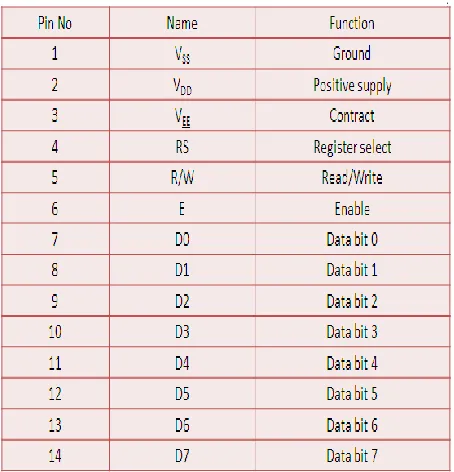
Liquid Crystal Display (LCD)
Microcontroller controlled LCD are widely used in many application, having replaced most of their LEDs because of their low power consumption and flexible graphics display. This intelligent LCD module can show 160 different characters. The entire system is supplied with a 5V power supply. Data are entered via the data line (D0-D7) as shown in the following table 1.
Relay Driver (ULN2003A)
ULN2003 is a high voltage and high current Darlington arrays IC. It contains seven open collector Darlington pairs with common emitters. Each channel rated at 500mA and can withstand peak currents of 600mA. A Darlington pair is an arrangement of two bipolar transistors. These versatile devices are useful for driving a wide range
of loads including solenoids, relays DCmotors, LED displays filament lamps, thermal print heads and high power buffers. The pin connection of ULN 2003A is displayed in fig. 6.
THE MAIN CONTROL CARD
In this system, there are two input pins and six control output pins at main controller card shown in fig. 6. Implementation block diagram for the control card is described in Fig. 6. The control card is intended for 1.5 horse power (Hp) for consumer application for air conditioning system. The first input is a LM35 temperature sensor. It senses the temperature with the variation of component in this control card is microcontroller.
FIGURE 6. PIN DIAGRAM OF ULN 2003
The main environment and connected to PIN RA0 of the PIC16F877A. The rest pins, PORTA1, PORTA2, PORTA3, and PORTA4 are applied for LEDs display. LEDs respectively on this controller will light on as soon as receiving the signals from IR remote control. The next input pin is given for IR receiver connected to another RB0 pin. The IR receiver in the circuit is TSOP1736. It receives the signals from IR transmitter and retrieves the original modulating signal from the 36 kHz carrier. The output will be active low. Output of TSOP1736 will be HIGH when no signals fall on it and the output will be LOW when 36 KHz infrared rays fall on it. This IR receiver sensor decodes the demodulated frame from sensor module to corresponding commands and address data byte.
The control command signal pin from IR is driven to set up running mode, temperature, fan speed and process. Then, the first output is used to control compressor and connected to PINRC0 to drive the circuit. The next pins pair is used for outdoor fan and swing fan connected with PINRC1 and PINRC2. The last three pins are utilized for indoor fan speed in the range of low, medium and high connected to PINRC4, PINRC5 and PINRC6. The control card consists of five relays for connection of output loads. The five relays with 12V are used, that cannot be controlled by the microcontroller directly. In this system, ULN 2003A is used to drive the desired output loads and
depends on the output bits of microcontroller. The four LEDs on microcontroller which indicates power ON/OFF and mode selection from the user preference by IR. LCD module interfaced with microcontroller is used to indicate the operation of control card for air conditioning system. In fig. 7, LCD is connected to RD0, RD1, RD2, RD3, RD4, and RD5 PINs for microcontroller, so the controlling data displays the LCD. E, RS and RW of LCD are used for control purposes. The rest output pins are used for showing status and modes of air conditioner. The system is supplied with a 5 V power supply.
CONCLUSION
REFERENCES
[1] H. S. Lee. D. Hodges, and P. R. Gray, “A self- calibrating 15 bit CMOS A/D converter”, IEEE J. Solid state circuits 19, 1984, 813- 819.
[2] M.de. Wif, k-s. Tan, R.K.Hester, ″A low-power 12-b analog-to-digital converter with on-chip precision trimming”, IEEE J. Solid-state circuits. 28, 1933, 455-461.
[3] K.S.Tan. S.Kiriaki, M.De Wit, J.W.Fattaruso, C.Y.Tayet al “Error correction techniques for high- performance differential A/D converters”, IEEE J. Solid-state circuits, 25, 1990, 1318- 1326.
[4] J.W.Fattaruso, S.Kiriaki, M.Dewit, and G.Waxwar. “Self-Calibration techniques for a second-order multi bit sigma-delta modulator”, IEEE J. Solid-state circuits, 28, 1993, 1216-1223.
[5] T.H.Shu, B.S.Song, and K.Bacrania, “A 13-b 10-M samples ADC digitally calibrated with oversampling Delta-sigma converter”, IEEE J. Solid-state circuits, 4, 1955, 433-452.
[6] B.Razavi and B.A.Wooley, “A 12-b 5-M samples Two-step CMOS A/D converter”, IEEE J. Solid-State circuits, 27, 1992, 1667- 1678.
[7] B.S.Song, S.H.Lee, and M.F.Tompsett, “ A10-b 15-MHz CMOS recycling two steps A/D converter”, IEEE J. Solid-state circuits, 25, 1990, 1328-1338.
[8] Joao Goes, Joao C. Vital, and Jose E.France “Systematic Design for optimization of High Speed Self-Calibrated Pipelined A/D converters”, IEEE Trans. Circuits system II, 45, 1998, 1513- 1526.
[9] M.M. Furuta, M. Nozawa, and T. Itakura, “A 10-bit, 40-MS/s, 1.21mW Pipelined SAR Using Single Ended 1.5-bit/ cycle Conversion Technique”, IEEE J. Solid State Circuits, 46(6), 2011, 1360-1370.
[10] H. Lee, -Y, “Zero-Crossing-based 8-bit 100 MS/s Pipelined analog-to-digital Convertor with offset Compensation”, IET Circuits, Devices & Systems, 5(5), 2011, 411- 417.