Volume-6 Issue-1
International Journal of Intellectual Advancements
and Research in Engineering Computations
Design and analysis of impeller- openwell monoblock pump efficiency improvement
D.Ravichandran
1, P.Saravanakumar
12, S.Syed saleem
2, S.Vignesh
2, D.Vijay
2,
2
Assistant Professor
1, UG Students
2Department of Mechanical Engineering, Nandha Engineering College, Erode-52,
Tamil Nadu, India.
1
[email protected]
,
2[email protected]
Abstract - This article is proposed based on the experimental analysis of open well monoblock pump. Pump is a mechanical component used for transportation of fluid which may be linear or vertical manner, with the use of two main components Impeller and casing. The efficiency of the pump is based on the discharge (lps) and total head (m). In this modern era, with the usage of analysis and modeling software, the pump efficiency is calculated based on the key parameters of the Impeller design & volute casing. This research is stipulated on the use of theoretical analysis in combination with CFD concepts to determine the optimum value of blade vane angles for maximum efficiency. The efficiency obtained from CFD (flow test) is compared with the original data's from pump xzmanufacturer through testing and efficiency improved by changing vane angle.
KEYWORDS: CFD, Total head, discharge, Impeller, Volutecasing,etc.
I. INTRODUCTION
In present, of submersible pump (or sub pump, electric submersible pump (ESP)) is a device which has a hermetically sealed motor close-coupled to the pump body. The whole assembly is submerged in the fluid to be pumped. The main advantage of this type of pump is that it prevents pump cavitation, a problem associated with a high elevation difference between pump and the fluid surface. Submersible pumps push fluid to the surface as opposed to jet pumps having to pull fluids. Submersibles are more efficient than jet pumps.
Ca. 1928 Russian oil delivery system engineer and inventor Armais Arutun off successfully installed the first submersible oil pumps. In 1929, Pleuger Pumps pioneered the design of the submersible turbine pump, the forerunner of the modern multi-stage submersible pump. In the mid-1960 the first fully submersible deep-well water pump
was developed by Poul Due Jensen who later went on to start Grundfos.
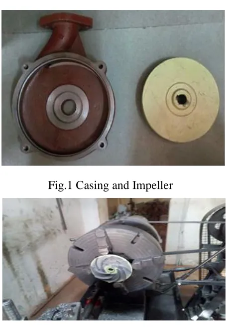
Fig.1 Casing and Impeller
Fig.02
Fig.3 Cross Section of Impeller
II.LITERATURE SURVEY
[1] Bacharoudis, 2008 In a research by, Stated that, the influence of the outlet blade angle implicit the performance of pump along with CFD simulation. By varying the outlet blade angle, performance curve becomes smoother and flatter. In this study, the performance of impeller with same outlet diameter having different outlet blade angles is evaluated and concluded that, when pumps operate at nominal capacity, the gain in the head is more than 6% than the previous head, If the outlet blade angle is increases from 20° to 50°.Hazeeb Halid et al, conducted an experimental analysis of solid desiccant wheel dehumidifier and stated that regeneration temperature increases more moisture is removed from the process air due to enhanced heating of desiccant wheel surface.
[2] Manivannan, 2010 An empirical study by about the CFD analysis of mixed flow impeller is done and the results are compared with the existing impeller having head H = 19.24 m and efficiency � = 55%. In the analysis three modified model of the impeller were created by changing the inlet and outlet vane angles and concluded that by varying the outlet angle performance is effected the most.
[3] Rajendran 2012 In another research similar to, describes that the simulation of flow in the impeller of a centrifugal pump having head H = 10m and discharge Q = 0.0125 m3/sec. The flow pattern, pressure distribution in the blade passage, blade loading plot at 50% span, stream wise variation of mass averaged total pressure was presented. He concluded that CFD predicted value of head at the design flow rate is approximately H =9.4528 m, and pressure contours show a continuous pressure rise from leading edge to the trailing edge of the impeller due the dynamic head developed by the rotating pump impeller.
[4] Urankar 2012 Additional to above statement,
equal divisions and varying vane inlet angle from hub to shroud. The model prepared is been analyzed in CFD tool CFX and its performance is analyzed at different flow rates. At, inlet the boundary conditions was 0 pa, and at outlet 500 m3/hr, 1800 rpm. Finally, concluded that increase in efficiency is due to little twist provided at the leading edge of the vane by varying the leading edge angle from hub to shroud, and small modification in the vane can give very good results.
[5] Mitul G. Patel, 2014 A review study by, mentioned that analysis of the impeller used in the mixed flow submersible pump. Fluid flow (CFX) is used for the analysis purpose and due to constant mass flow rate, same boundary condition, i.e. the mass flow rate at the inlet and outlet was applied, the hub and shroud was defined as a wall. And obtained (1) pressure and velocity distribution in meridional view of impeller and in blade to blade view of impeller and concluded that the head generated by the CFX showed good agreement with the experimental head.
III.POSTIVE DISPLACEMENT PUMP BEHAVIOR AND SAFETY
Positive displacement pumps, unlike centrifugal or roto-dynamic pumps, theoretically can produce the same flow at a given speed (RPM) no matter what the discharge pressure. Thus, positive displacement pumps are constant flow machines. However, a slight increase in internal leakage as the pressure increases prevents a truly constant flow rate. A positive displacement pump must not operate against a closed valve on the discharge side of the pump, because it has no shutoff head like centrifugal pumps. A positive displacement pump operating against a closed discharge valve continues to produce flow and the pressure in the discharge line increases until the line bursts, the pump is severely damaged, both.
IV. POSITIVE DISPLACEMENT TYPES: A positive displacement pump can be further classified according to the mechanism used to move the fluid:
-type positive displacement: internal gear, screw, shuttle block, flexible vane or sliding vane, circumferential piston, flexible impeller, helical twisted roots (e.g. the Wendelkolben pump) or liquid-ring pumps
Reciprocating-type positive displacement: piston pumps, plunger pumps or diaphragm pumps
-type positive displacement: rope pumps and chain pumps
V. PROBLEM IDENTIFICATION
The Existing design is analyzed on two parts of the pump. They are
Impeller Casing
For both the parts the existing design is analyzed and it is found that overall efficiency while using the existing design is low and with an adjustable energy consumption. The maximum overall efficiency is found to be 26.36% at 2.21 lps. The need of the company is to improve the overall efficiency of the pump by 10% without affecting the energy consumption.
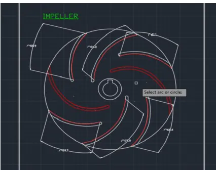
The Impeller can be redesigned in such a way that it can be able to perform much efficiently. Modification should be made on the vane angle of the impeller or surface area of the casing.
VI.SCOPE OF THE PROJECT
the open well submersible pumps.
ficiency given to the pump is studied.
casing.
VII.SYSTEM SPECIFICATION: While considering the system specification. The following things should be considered. 1. Impeller
2. Casing 3. Motor 4. Shaft
5. Bearing assembly
VIII
.
METHODOLOGY:EXISTING DESIGN
PROBLEM
ANALYZE
SOLUTION
IMPLEMENTATION
EXISTING DESIGN IX. PROPOSED DESIGN
The main objective of this project is to improve the efficiency of the given open well pump by modifying the design of the Impeller and Casing. Surface area of the Casing and vane angle of the Impeller are modified in the design and the above changes are analysed on the analysing software. Existing and modified design are made by using the solid works 2016 model and the above design is analysed though the solid works flow analysis. The existing design is having a medium range efficiency by doing this project, the efficiency of the pump gets increased and energy consumption gets decreased o minimized.
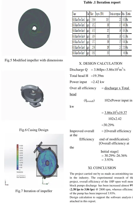
Fig.5 Modified impeller with dimensions
Fig.6 Casing Design
Fig.7 Iteration of impeller
Table .1 Iteration report
X. DESIGN CALCULATION
Discharge Q = 3.86Ips=3.86x10
2m
3/s
Total head H =19.39m
Power input =2.42 kw
Over all efficiency
= discharge x Total
head
(ῆ
overall) 102xPower input in
kw
= 3.86x10
2x19.37
102x2.42
=30.29%
Improved overall
= [Overall efficiency
at the
Efficiency end of modification]-
[Overall efficiency at
the
Initial stage]
= 30.29%-26.36%
= 3.93%
XI.
CONCLUSION
The project carried out by us made an astonishing task in the industry. The experimental research of this project, overall efficiency of the 1HP open well mono block pumps discharge has been increased almost 9%
(2.38 lps to 3.86 lps) @ 2800 rpm, whereas efficiency
of the pump has been improved 3.93%.
REFERENCES
[1] A., G. V. a. N., 1993. Impeller Pumps, Theory and design. Anon., n.d.
[2] B.J. Patil, D. V. B. S., n.d. Investigation into the causes of Pulsation of Flow of Hydraulic Pumps and Its Effects.
[3] Bacharoudis, E. C. F. A. E. M. M. D. &. D. P., 2008. Parametric study of a centrifugal pump impeller by varying the outlet blade angle. [4] Chaudhari, S. C. Y. C. O. &. A. B., n.d. A comparative study of mix flow pumps impeller cfd analysis and experimental data of submersible pump. International Journal of Research in Engineering & Technology (IJRET).
[5] Chhanya, V. G., n.d. Design and Analysis for the Improvement of Impeller using CFD analysis.
[6] Chhaya, V., n.d. Design and Cfd Analysis Of Submersible Pump Impeller".
[7] D. Prem kumar ., M. B., n.d. Implementation of Quality Function Deployment in Pump Industry.
[8] DAMBOR, A. B., n.d. Performance Improvement of mixed flow pump in Impeller. [9] karnath, S., n.d. Design, Analysis and Modellin of Impeller.