©2014 JNAS Journal-2014-3-9/935-942 ISSN 2322-5149 ©2014 JNAS
Capability of “Direct Strength Method” for welded
steel sections with non-slender components
Hossein Daneshpajouh
Marand Faculty of Engineering, University of Tabriz, Tabriz, Iran
Corresponding author:
Hossein Daneshpajouh
ABSTRACT: In this investigation, a modern process of designing named “Direct Strength Method” (DSM)
for the columns with welded steel sections formed of the sheet with non-slender components under uniform compression into two statues, with and without effect of residual stress based on AISC regulations has been expressed and evalouted. A set of theoretical and software studies have been conducted on the welded non-slender sections of box and H shaped with the conventional steel sheets with the constant thickness of 8 (mm) and yield stress of 2400 (Mpa) in order to reach the ultimate strength of the aforementioned columns. Subsequently, using DSM for final predicting such sections like these needs numerical stability analysis and it is also required to determine the behavior of elastic buckling of the member in a range of actions and reactions related to local and general buckling modes. Hence it is mandatory for the sections to be analyzed through CUFSM software based on the finite strip method (FSM) in order for simulating the mentioned behavior. So as to complete the basic information, the effect
of initial imperfections and defects on the applied sections and the behavior ofpost-buckling strength has
been surveyed through using non-linear analysis of ABAQUS software based on finite element method (FEM) with the assumption of effect of above statuses. Eventually, the accuracy and precision of DSM equations have been compared to the final amounts obtained from AISC regulations for columns with non-slender sections.
Keywords: Direct Strength Method, Welded non-Slender Sections, Post-Buckling Strength, Linear and
Non-linear Analysis, Residual Stress, AISC Regulations.
INTRODUCTION
DSM method as a set of equations was presented for cold-formed steel members in the AISI regulations for the first time in the North America (1). Subsequently, after conducting wide researchers, it was developed in Australia and New Zealand as a method for designing cold-formed steel members such that it could be used as a method for designing compressive, bending, shear, beam columns and perforated cold-formed steel members. In the recent years, it was intensively attempted to use this method as a manner to design compressive steel members based on a rational analysis throughout using elastic buckling solutions related to the corresponding member directly. Briefly, it could be said regarding the columns that the start of DSM method was a survey for determining distortional buckling of thin-walled members at university of Sydney specially Hancock who has conducted numerous researches relevant to this field and concluded that the compressive strength obtained at the distortional elastic mode of the section is proportional to the slenderness for different kinds of sections (2).
936
Development of DSM equations based on Winter`s relation as the curve of design strength has been done through various tests by Schafer and Pekoz which finally led to creation the direct strength method for designing compressive members considering the below notion (5).
In fact, the definition of DSM is related to using self-dimensions of the section with the effective design stress
ρFy instead of using the effective width of the elements with yield fracture stress in the effective width method.
(1) Ag.Pne = Pn=ρ.Py=(ρ.Ag).Fy=Ag.(ρFy)
ρ= 1/λ (1- 0.22/ λ) , λ > 0.673 (2)
Where, ρ is the effective stress factor or the limited stress coefficient.
This notion is applied on the whole of the section as a limited stress which can be named for each of various buckling modes under different pressure as the limited buckling step of the corresponding mode which its conclusion is direct strength method (DSM). Actually, DSM presents equations with the aforementioned notion for cold-formed members in the following modes through considering various actions and reactions relevant to buckling modes and
with replacing Pne in columns and Mne in beams instead of Py and My, respectively.
1- Local buckling mode
In this mode, the elements forming the section were only rotated and bent at their junction and the storage after buckling was high at the local mode and happened at the minimum wavelength.
DSM relations for compressive members at the local mode:
(3) , λl≤ 0.776 Pnl = Pne
, λl> 0.776 Pnl =(1-0.15(Pcrl/Pne)0.4)*(Pcrl/Pne)0.4*Pne l = √(Pne /Pcrl) λ
Where, Pnl is the ultimate strength of the section under local mode and Pcrlis the critical local strength of the
section from the CUFSM output and Pne is the strength of the section at the elastic state.
2- Distortional buckling mode
In this mode, the junction points of the web and flange changed and the elements have revolution movement addition to the rotation. After that, the storage after buckling at the distortional mode is average and occurred at the medium wavelength.
DSM relations for compressive members at the distortional mode:
Pnd=(1-0.25(Pcrd/Pne)0.6)*(Pcrd/Pne)0.6*Pne , λd>0.561
λd≤ 0.561 (4) Pnd = Pne d = √(Pne /Pcrd) λ
Where, Pnd is the ultimate strength of the section under distortional mode and Pcrdis the critical distortional strength
of the section from the CUFSM output and Pne is the strength of the section at the elastic state.
3- General buckling mode
Under this mode, rotation or revolution or a combination of both occurred at the whole of the section without bending the elements of the section and also the storage after buckling is less and had longer wavelength in this mode.
DSM relations for compressive members at the general mode:
Pne = (0.658λc^2 ) *Py , λc≤ 1.5 (5)
937
Py = Ag. Fy
In this study, it has been attempted to adopted analysis of CUFSMandABAQUSsoftware programs and with
the help of the effect of local and general actions– reactions and the concept of post-buckling storage related to the sections on the ultimate strength of compressive members in the above statues, can use the advantages created from DSM for analyzing non-slender built-up welded H and box shaped sections. In addition, the revised design formulas for the mentioned sections have been presented. Eventually, it has been compared and concluded based on AISC regulations.
s
2 - Investigation procedure
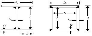
In accordance with the definition, slender sections are the ones which usually made of several slim elements. Generally, columns with the mentioned sections buckle in the local buckling mode and general buckling mode such as lateral, torsional and lateral-torsional. In spite of being lower the stress of local buckling in comparison to the general buckling stress and available actions – reactions between two modes, the ultimate nominal strength of the columns decrease. Consequently, it made the determination of elastic local buckling stress under uniform pressure have particular significance and it leads to create the storage after buckling. In this event, the opposite of this subject has occurred for non-slender sections (compressed or uncompressed). Accordingly, a set of theoretical and software studies is conducted on the welded non-slender sections in shape of box and H with the convectional steel sheets with a constant thickness of 8 millimeters and the yield stress of 240 Mpa. In addition, the geometry of the sections is defined through AISC regulations as follows:
Figure 1. The geometry of welded sections of box and H shaped
The criterion for choosing the sections is such that it should , the ratio of the width to the thickness of the components making the section has to be located at the regulation non-slenderness limitation as follows (6):
1- Elements with two depended edges under uniform pressure:
h/tw or b/tf <1.4√(E/Fy) (6)
2- Elements with one depended edge under uniform pressure:
b/tf <0.95√(Kc.E/FL)
(7)
, FL=0.7Fy Kc=4/√h/t (0.35≤Kc≤0.76)
Other characteristics of the conventional soft steel have been considered from AISC regulations as follows:
0.3 =ν E=2*106 kg/cm2 ,
G=769230.7 kg/cm2
938
Table1. Characteristics of sections
h/t b/t d (cm) bf (cm)
Sections
10.5 10.5 5
10 B 10x5
10.5 5.75 10
10 H 10x10
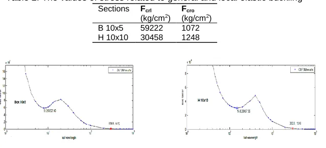
In order to model the behavior of the sample sections with definition the geometry the welded sections made of sheet and the features of corresponding materials in CUFSM software, the geometric characteristics of the sections could be obtained directly. The diagrams of load factor–wavelength of all sections are determined through conducting the analyses in the compressive loading state uniformly. The curves, obtained from elastic analysis of CUFSM for the sections mentioned on table 1, have been show in figure 2. In accordance with the mentioned issue, the values
of general and local elastic buckling stress)Fcro( have been shown on table 2 briefly.
Table 2. The values of stress related to general and local elastic buckling
Figure 2. Curves related to elastic analysis of CUFSM
The minimum point on the diagram shows the value of Fcrl related to the sections which equals Pcrl/Ag for a
section under uniform pressure. The horizontal axis of the graph (wavelength) indicates number of half-sine waves equal m=L/b and the vertical axis (stress factor) presents the domain of half wave or the amount of elastic buckling
stress of the member in the range of the wavelength relevant to the corresponding point withdouble hinged bottom.
Linear and non-linear analysis of ABAQUS
To complete the basic data obtained from elastic analysis of CUFSM and reach the ultimate load of selected sample sections, it is mandatory to survey the non-linear analysis of welded non-slender sections in the non-linear range by ABAQUS software. For this purpose the effect of initial defects and imperfections, sections as a combination of all deformations resulted from linear buckling modes with applying small coefficients as a primary geometric model of the section, has been applied in non-linear buckling analysis. In fact, geometric local imperfections and defects present the displacements gained from local buckling of slim components related to the sections in various buckling modes in terms of eigenvalue. In accordance with the conducted study works and with considering that the most common method for applying the effect of initial imperfections and defects on various sections is the same as elastic buckling analysis, the maximum domain of displacements of eigenvalue is applied in a percentage of the thickness related to section as the effect of local initial imperfections and defects in three first modes of the local elastic buckling obtained from linear analysis which are 0.001t, 0.005t, 0.01t in order.
General parameters of simulation with ABAQUS:
1. Simulation of the geometry, dimensions and geometry specifications of the columns sections has been matched to the aforementioned matters.
2. Von Misses stresses have been used for the application in the theory of plastic sections.
3. All columns have been defined as two-dimensional shell elements (Shell, S4R (. In fact, S4R element
indicates 6 degrees of freedom in each node with direct bilinear interpolation, concurrent with applying the effect of membrane strains considered as reduced integration.
4. The length of all columns is 3 meters and their supports are modeled double hinged support. Schematic model of the support conditions in a column with H shaped section has been shown in figure 3.
Fcro
(kg/cm2) Fcrl
(kg/cm2)
Sections
1072 59222
B 10x5
1248 30458
939
5. Loading of the columns is vertically at longitudinal direction of the column which has been allowed to displace at the loading direction. This loading is applied as the uniform pressure on the cross section at the free bottom in the vertical direction. Figure 3 shows the schematic model of the loading.
Figure 3. Schematic model of the support conditions and the loading of the column
6. Meshing relevant to elements of the total sections has been used in the size of 0.1 small dimension of the section regularly.
7. Figure 4 indicates an illustration of regular meshing elements related to box and H shaped sections surveyed in the analysis.
Figure 4. Meshing the elements of the sections
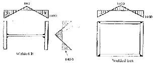
8. Amount and distribution of residual stress for the sections mentioned on table 1, considered such ideal linear form that have been show in figure 5.
Figure 5. Distribution of residual stress in sections of box and H shaped
Simulation of linear analysis with ABACUS
Elastic linear analysis of all columns for the effect of initial imperfections and defects values is done through using Buckle order in Lineir Perturbation state which the specific first mode of local buckling at Buckle step is considered as the initial imperfections and defects for all sections and it is saved for non-linear analysis of buckling by applying corresponding coefficients.
Simulation of non-linear analysis with ABACUS
940
deformation and final load of column will be gained from non-linear bucklinganalyze.
DSM equation with and without effect of residual stress
The revised equation of DSM for residual stress state with assumption has been introduced below:
Pne , λl ≤ λlim
1/λl* (α - β/λl) * Pne , λl ≥ λlim Pnl =
= (Pne/Pcrl)1/n lλ
β = 0.25 – (λlim– 0.5) 2
or (9)
Pne , λl ≤ λlim Pnl =
(Pcrl /Pne)1/n *(1-β.(Pcrl/Pne)1/n) * Pne , λl ≥ λlim
The revised equation of DSM for residual stress state with assumption has been introduced below:
Pne λl ≤ λlim
β / λl2 ) * Pne λl ≥ λlim ) Pnl =
= (Pne/Pcrl)1/n λl
β=(λlim)1/n
or (9)
Pne λl ≤ λlim
Pnl =
β *(Pcrl /Pne)2/n * Pne λl ≥ λlim
In the above equation, Pne is the minimum general strength of the column in the bending or torsional or
torsional-bending elastic modes based on the AISC regulations.
Pcrl is the elastic local buckling obtained from CUFSM analysis and Pnl is the ultimate nominal strength of the
column with local buckling mode and λl is the slenderness relevant to the local buckling of the section and λlim is the
slenderness limited to the boundary of elastic and inelastic buckling in action-reaction with the general buckling mode.
In order to determine n, the degree of post- buckling strength the sample sections, the concept of inelastic
buckling of columns is used which could be written for the motioned no-linear zone as follows:
fpb = π2 Et /λn
fpb= fu–fp (fu –fp) = π2 Et /λn (10)
λn =π2 Et /(fu – fp) n =Log(π2 Et /(fu – fp)) /Log λ
The ratio of Fu/Fne obtained from the analysis is the same as the limited slenderness factor which equals:
lim = Fu / Fne λ
Where, fpb is the amount of stored strength of local post- buckling, fu is the ultimate strength of the section related
941
The P-Δ curves related to non-linear analysis of the buckling with and without residual stress for sample sections have been drawn in figures 6 and 7.
Figure 6. P-Δ curves relevant to the non-linear analysis of the buckling with residual stress
Figure 7. P-Δ curves relevant to the non-linear analysis of the buckling without residual stress
The summary of the results at the state of with and without residual stress has been presented on tables 3 and 4.
Table 3. the results summarized from non-linear analysis with residual stress
Table 4. the results summarized from non-linear analysis without residual stress
DISCUSSION AND CONCLUSION
According to above graphs and tables , we can express that fristly , in this kind of sections, non post-buckling
strength didn’t make and absolutely be Fp = Fu . in accurate way , (1/n ) proportion lead to being zero and amount of
slenderness related to local bucking section being equal to 1. Secondly , according to 5 equations and results of table 1 , furthermore in residual stress and washout’s statue , slenderness limited to the boundary of elastic and
inelastic buckling going to larger than 1.It means that lλ < limλ
Verisimilitude of the results obtained from DSM relations and AISC regulations
According to AISC regulations, non-slender sections (compressed and uncompressed) , defiantly, has general buckling mode that caused to determination of ultimate strength of them and local buckling never made in.
Up to above words and context of DSM that based on determine of local buckling elastic stress and considering local and general mode action-reactions, Finlay, in equations relate to DSM fore welded non-slender sections always
Pnl = Pne and the results accuracy are In accordance with Euler diagrams of AISC.
Allowable strength design method (ASD) has been used so as to compare and estimate the percentage of error between the ultimate strength obtained from the proposed DSM relations and AISC regulations which the allowable strength design of criterion sections under the uniform pressure in the state of residual stress has been determined through definition of safety factor and it has been indicated on table 6 briefly.
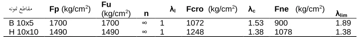
λlim Fne (kg/cm2) λc
Fcro (kg/cm2) λl
n Fu
(kg/cm2) Fp (kg/cm2)
هنونم عطاقم 2.21 900 1.53 1072 1 ∞ 1990 1990 B 10x5 1.71 1078 1.38 1248 1 ∞ 1850 1850 H 10x10 λlim Fne (kg/cm2) λc
Fcro (kg/cm2) λl
n Fu
(kg/cm2) Fp (kg/cm2)
942
According to table (6), the comparison -between the results obtained from AISC and the proposed DSM relations- shows that the percentage of the error was averagely 5 percent which expresses a proper agreement. Furthermore, in residual stress state and with the assumption of Q=1, the suggested curve of DSM presents bigger and conservative amounts compared to the Euler curve AISC whereas for Q<1, the proposed DSM values in compare to the AISC regulation values express in 2 below forms :
1- For 0.695 and 0.81 up to 1 slenderness, proposed DSM values are so close to AISC values.
2- For bigger than 1 slenderness, proposed DSM values are little bigger and
Conservative than AISC values.
REFERENCES
AISC. 2006. “Steel Frame Design Manual AISC." American Institute of Steel, 360-05 / IBC.
AISI “North American Specification for the Design of Cold-Formed Steel Structures" American Iron and Steel Institute,
Washington, D.C, AISI-S100.
Hancock GJ, Kwon YB and Bernard ES. “Strength design curves for thin-walled sections undergoing distortional buckling" Journal
of Constructional Steel Research; 31(2–3):169–86.
Hancock GJ, Murray TH and Ellifritt D. “Cold-Formed Steel Structures to the AISI," Specification, Copyright © 2001 by Marcel Dekker, Inc.
Schafer BW and Pekoz T. “Direct strength prediction of cold-formed steel members using numerical elastic buckling solutions .“
In: Proceedings of the fourteenth international conference on cold-formed steel.