CI024 | Published : 10- April -2018 | March-April - 2017 [(4) 5: 343-351]
2nd International Conference on Current Research Trends in Engineering and Technology
© 2018 IJSRSET | Volume 4 | Issue 5 | Print ISSN: 2395-1990 | Online ISSN : 2394-4099 Themed Section: Engineering and Technology
343
Human Computer Interaction System Using Retina
Neha Pathak, Shivani Thakur, Pooja Solanki, Nidhi Shah
1-3 BE- Student, Information Technology, Sigma Institute of Engineering, Vadodara, Gujarat, India 4BE- Assistant Professor, Information Technology, Sigma Institute of Engineering, Vadodara, Gujarat, India
ABSTRACT
There are number of traditional techniques such as Head and Hand Movement Tracking Systems which are use for mouse control some of them hardware part is require, not accurate but here we use real-time retina movement for cursor control by making use of image processing. The system real time track the eye retina and based on retina movement assign the new location to cursor. For that first I will detect the face and then real time track the movement of retina. For assigning the location to cursor using JAVA robot class. It helps the special people to share their knowledge with the world.
Keywords: Retina, Movement, Cursor, ROI (Region Of Interest), Iris Detection
I.
INTRODUCTIONPeople with physical disabilities face a lot of problems in communication with their fellow human beings. The design of an eye-controlled mouse system with an emphasis on the Human-Computer-Interaction (HCI) based on Open CV has been presented. Computers can be used by persons with disabilities for communication, environmental control, source of information and entertainment.
In the proposed system, the design of the software is in such a way that, when the user faces the camera, the pixel position will be fixed by the software. The human face recognition is given importance in order to provide facilities like pixel point determination, authentication, etc., Since the software determines the pixel point, the user need not worry about the loss of pixel point when user shakes his/her head. Because when the head is shaken fast, the pixel point gets lost, when the user again faces the camera without any
movement, then the pixel point is determined again by the software. This shows that the stability of the pixel position is high compared to existing system. The cursor will not vibrate more as the stability of pixel point very high compared to the existing system.
These are the following algorithms are included for
1. Image Recognition 2. Image Detection 3. Tracking
1. Image Recognition:-
as fingerprint or eye iris recognition systems. Some facial recognition algorithms identify faces by extracting landmarks, or features, from an image of the subject's face. For example, an algorithm may analyze the relative position, size, and/or shape of the eyes, nose, cheekbones, and jaw. These features are then used to search for other images with matching features. Other algorithms normalize a gallery of face images and then compress the data, only saving the data in the image that is useful for face detection. A probe image is then compared with the data. One of the earliest, successful systems is based on template matching techniques applied to a set of salient facial features, providing a sort of compressed face representation.
Recognition algorithms can be divided into two main approaches, geometric, which looks at distinguishing features or photometric, which is a statistical approach that distill an image into values and comparing the values with templates to eliminate variances.
2. Image Detection:
Image detection is a computer technology that determines the locations and sizes of images in arbitrary (digital) images. It detects image features and ignores anything else, such as buildings, trees and bodies. Image detection can be regarded as a specific case of object-class detection; In object-class detection, the task is to find the locations and sizes of all objects in an image that belong to a given class. Examples include upper torsos, pedestrians, and cars. Early image detection algorithms focused on the detection of frontal human faces, whereas newer algorithms attempt to solve the more general and difficult problem of multi-view image detection. That is, the detection of faces that are either rotated along the axis from the face to the observer (in-plane rotation), or rotated along the vertical or left-right axis (out-of plane rotation), or both. Many algorithms implement the image-detection task as a binary pattern-classification task. That is, the content of a given part
of an image is transformed into features, after which a classifier trained on example faces decides whether that particular region of the image is a face, or not. Often, a window-sliding technique is employed. That is, the classifier is used to classify the (usually square or rectangular) portions of an image, at all locations and scales, as either faces or no faces
(background pattern).
3. Tracking:
Image is tracked by two de correlated detectors:
Color-Based Face Tracker and Viola-Jones Face Detector.
Both algorithms made a good showing by their robustness and speed. They are not exacting to video quality and resolution. Our initial attempt at providing mouse movement was to track the recognition of the signs and each time new location for the sign was detected update the position of the mouse on the kiosk display. Unfortunately this resulted in unacceptably jerky movement of the mouse.
This was caused by two factors:
1. During motion the sign was not always detected because of blurring in the image. This resulted in the sign being occasionally recognized and the mouse therefore being moved in jumps rather than smoothly. 2. The recognizer finds the bounding box for the gesture and takes the center point of the bounding box as the position of the sign. As the hand moves the shape of the bounding box changes and this gives rise to erratic position estimates that are unpleasing to the user. We overcame the above problems by separating the motion of the kiosk mouse pointer from the recognition of the sign.
Optical Flow in a Region
The optical flow in the region that contains the hand sign is computed on each frame. This provides a very smooth estimate of movement of the sign. The above algorithm provides a very smooth and usable mouse movement on the kiosk. Upon entry to the “Gesture Tracking” state a region is computed that is slightly larger than the bounding box of the hand sign which shows the bounding box and an outer box used for calculating the optical flow. The optical flow is computed for the entire optical flow region and the average flow within the region is passed into the Kalman filter. Whenever a sign is recognized, the position in the gesture box is updated but recognition of a sign never moves the mouse pointer–only optical flow results in mouse movement.
II.
SYSTEM ANALYSISA. Wireless Mouse Control System is technique Bluetooth technology is used for controlling mouse over a 10m to 15m range. But this technology is also based hand controlling.
Fig 1: Wireless Mouse
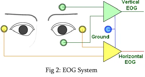
B. Electro-oculography (EOG):
It is a new technology of placing electrodes on user‟s forehead around the eyes to record eye movements. EOG is a very small electrical potential that can be detected using electrodes. The majority of the people using this setup may have severe cerebral palsy or been born with a congenital brain disorder or suffered traumatic brain injury, for example from automobile
or drowning accidents. This technique is adapted because it is inexpensive and accurate The anatomy of the eye is shown in the Fig. 1. The light entering the pupil, is focused, inverted by the cornea and lens and projected onto the back of the eye (fovea). The fovea defines the center of the retina with the region of highest visual acuity. The retina houses seven layers of alternating cells and processes which convert a light signal into a neural signal (transduction). The actual photoreceptors are the rods and cones, but the cells that transmit to the brain are the ganglion cells. Cones provide the focus on fine detail and distinguish color. They require relatively high levels of illumination to operate. Rods, on the other hand, are much more sensitive to light, providing superior capability to detect movement in low levels of illumination. The axons of the ganglion cells make up the optic nerve, the single route by which
information leaves the eye.
Fig 2: EOG System
device, in which an IR camera is mounted on a computer screen, and secondly a head-mounted device, in which an IR camera is placed on user‟s head. This technique is accurate but expensive.
Fig 3: Head Movement Tracking System
D. Hand gesture is technique used tracking the hand movement. Based on the different movement assign the mouse location or movement. In this technique different color detection techniques is used. Here hand gesture is plays an important role.
Fig 4: Hand gesture
III.
PROPOSED SYSTEM:
A. Face Detection and Tracking:
Computer vision face tracking is an active and developing field, yet the face trackers that have been developed are not sufficient for our needs. Elaborate methods such as tracking contours with snakes, using Eigen space matching techniques, maintaining large sets of statistical hypotheses, or convolving images with feature detectors are far too computationally expensive. We want a tracker that will track a given face in the presence of noise, other faces, and hand movements. Moreover, it must run fast and efficiently so that objects may be tracked in real time (30 frames per second) while consuming as few system resources as possible. In other words, this tracker should be able to serve as part of a user interface that is in turn part of the Computational tasks that a computer might routinely be expected to carry out. This tracker also needs to run on Inexpensive consumer cameras and not require calibrated lenses.
Robust statistics are those that tend to ignore outliers in the data (points far away from the region of interest). Thus, robust algorithms help compensate for noise and distractors in the vision data. We therefore chose to use a robust nonparametric technique for climbing density gradients to find the mode of probability distributions called the mean shift algorithm. (The mean shift algorithm was never intended to be used as a tracking algorithm, but it is quite effective in this role.) The mean shift algorithm operates on probability distributions. To track colored objects in video frame sequences, the color image data has to be represented as a probability distribution; we use color histograms to accomplish this. Color distributions derived from video image sequences change over time, so the mean shift algorithm has to be modified to adapt dynamically to the probability distribution it is tracking. The new algorithm that meets all these requirements is called CAMSHIFT.
For face tracking, CAMSHIFT tracks the X, Y, and Area of the flesh color probability distribution representing a face. Area is proportional to Z, the distance from the camera. Head roll is also tracked as a further degree of freedom. We then use the X, Y, Z, and Roll derived from CAMSHIFT face tracking as a perceptual user interface for controlling commercial computer games and for exploring 3D graphic virtual worlds.
B.Training a Cascade of Classifiers:
The cascade design process is driven from a set of detection and performance goals. For the face detection task, past systems have achieved good detection rates (between 85 and 95 percent) and extremely low false positive rates (on the order of 10−5 or 10−6). The number of cascade stages and the size of each stage must be sufficient to achieve similar detection performance while minimizing computation. Given a trained cascade of classifiers, the false positive rate of the cascade is Where F is the false positive rate of the cascaded classifier, K is the number of classifiers,
and fi is the false positive rate of the ith classifier on the examples that get through to it. The detection rate is Where D is the detection rate of the cascaded classifier, K is the number of classifiers, and di is the detection rate of the ith classifier on the examples that get through to it. The number of features evaluated when scanning real images is necessarily a probabilistic process. Any given sub-window will progress down through the cascade, one classifier at a time, until it is decided that the window is negative or, in rare circumstances, the window succeeds in each test and is labeled positive. The expected behavior of this process is determined by the distribution of image windows in a typical test set. The key measure of each classifier is its “positive rate”, the proportion of windows which are labelled as potentially containing a face. The expected number of features which are evaluated is:
The training algorithm for building a cascaded detector:
User selects values for f , the maximum acceptable false positive rate per layer and d,
the minimum acceptable detection rate per layer. User selects target overall false positive rate, F target.
P = set of positive examples N = set of negative examples F0 = 1.0; D0 = 1.0
i = 0
while Fi > F target
i ←i + 1
ni = 0; Fi = Fi−1 while Fi > f × Fi−1 ni ← ni + 1
× Di−1 (this also affects Fi ) N ←∅
If Fi > Ftarget then evaluate the current cascaded detector on the set of non-face images and put any false detections into the set N.
C. Eye Detection :
The system captures RGB video sequence and transforms the green component of each image frame i(x,y) into the integral image representation I(x,y) as follows:
S(x,y)=S(x,y-1) +i(x,y)………..(1) I(x,y)=I(x-1,y)+S(x,y)………(2)
where S(x,y) is the cumulative row sum, S(x,-1)=0, I(-1,y)=0. The integral image is then scanned (pixel by pixel) by a sixsegment rectangle, computing the sums of pixel values in each segment. For instance, the sum of pixels within rectangle 5 is defined as:
Sum(5)=I(x2,y2)+I(x1,y1)-I(x2,y1)- I(x1,y2)
The SSR filter then compares the computed sums of the segments as follows:
Sum(1) < Sum(2) and Sum(1) < Sum(4)…………..(3) Sum(3) <Sum(2) and Sum(3)<Sum(6) ……….(4)
If the above criteria (3)(4) are satisfied, the SSR is considered to be a candidate for Between-The-Eyes (BTE) pattern and two local minimum (i.e. dark) points each are extracted from the regions 1,4 and 3,6 of the SSR for left and right eye candidates. As the eye candidates are selected, the
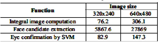
Table 1: No of faces Computation
BTE pattern is normalized by scaling, rotation and histogram equalization and then fed to Support Vector Machine (SVM) for confirmation. Thus for one face candidate, at most 4 patterns are tested. The search is then repeated for 6 other SSR filter sizes (120x72, 80x48, 60x36, 40x24, 30x18 and 20x12) in order to extract eyes of smaller faces if any. For the next frame, the BTE location is predicted as xp=2x1-x2, where xp is the predicted position, x1 and x2 are its positions in the most and the second most previous frames, respectively. Any incorrect prediction starts the full search. We implemented the algorithm in software and used specific instructions to count the number of computations performed. As results (Table 1) show, the face candidate extraction accounts for most of computational load. Because the face/eyes detection is general (no restriction on the number of faces, face size, motion, and rotation), it implies the following:
1. Full SSR filter scan over the whole image frame. 2. Repeats the scan six times (for all filter sizes).
Although this full search is necessary to find multiple faces in an image in general case, it might be redundant in particular applications. Taking into account features of target application is the only way to reduce complexity of the task.
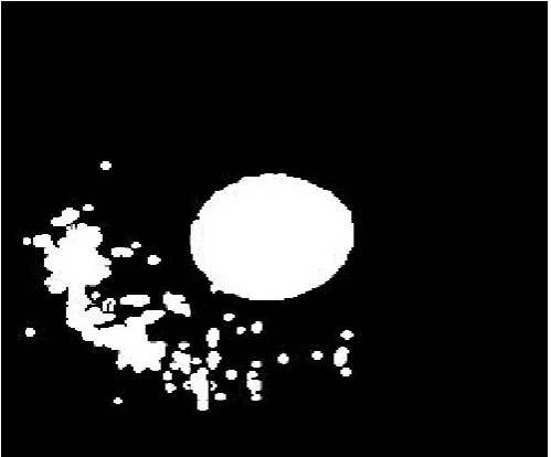
D. Retina Detection :
also developed an approach which detects the center of a region.
Fig 5: Retina
The algorithm for determining the center of a full zones looking like those from Fig. is based on the operation of subtraction of two images. In the image containing the zone whose center we want to find all pixels have binary values. Thus, in the interior of the zone we have pixels with value 1, and in the remainder area, (in the exterior of the zone) we have pixels with value 0. If in the initial image one pixel of value 1 haveall the four neighborhood pixels also of value 1, then in the new image on the position of that current pixels we put a value 1. Else, if the current pixel or some neighborhood pixel is 0, then the resulting pixel from the new image is 0. So, mathematically let us presume that p(i,j) is the current pixel from the initial image. If the value of pixel p(i,j) is 1, then we examine all the four neighborhood pixels:
p(i-1,j), p(i,j-1), p(i+1,j) si p(i,j+1).
Fig 6: Retina Detection
If the values of all of this four pixels are 1, then at the position determined by coordinates i,j on the new image we put a value of 1. So, the pixel p‟(i,j) from the new image would have the value 1. In the beginning we consider the new image as an empty image (or an image with all values 0). If one of the above conditions is not satisfied, then the pixel p‟(i,j) would have a value of 0.
center. So, the x coordinate and y-coordinate representing the center of the zone was calculated and so was the radius.
E. Mouse Movement :
Class Robot java.lang.Object java.awt.Robot
public class Robotextends Object
This class is used to generate native system input events for the purposes of test
automation, self-running demos, and constructor Robot
Robot:
public Robot()throws AWTException
Constructs a Robot object in the coordinate system of the primary screen.
Throws:
AWTException - if the platform configuration does not allow low-level input control.
This exception is always thrown
when GraphicsEnvironment.isHeadless() returns true SecurityException - if createRobot permission is not granted
GraphicsEnvironment.isHeadless(),
SecurityManager.checkPermission(java.security.Permi ssion), AWTPermission
Robot
public Robot(GraphicsDevice screen) throws AWTException
Creates a Robot for the given screen device. Coordinates passed to Robot method calls like mouseMove and createScreenCapture will be interpreted as being in the same coordinate system as the specified screen. Note that depending on the platform configuration, multiple screens may either: share the same coordinate system to form a combined virtual screenuse different coordinate systems to act as independent screens This constructor is meant for the latter case. If screen devices are reconfigured such that
the coordinate system is affected, the behavior of existing Robot objects is undefined.
Parameters:
screen - A screen GraphicsDevice indicating the coordinate system the Robot will
operate in. Throws:
AWTException - if the platform configuration does not allow low-level input control.
This exception is always thrown
when GraphicsEnvironment.isHeadless() returns true. IllegalArgumentException - if screen is not a screen GraphicsDevice.
SecurityException - if createRobot permission is not granted
Sample Code:
Robot robot1 = new Robot(); robot1.mouseMove(400,180); // Turn on the utility
robot1.delay(100);
robot1.mousePress(InputEvent.BUTTON1_MASK); robot1.delay(100);
robot1.mouseRelease(InputEvent.BUTTON1_MASK); //Wait for 2 minutes
robot1.delay(200);
// Move the mouse to disconnect button robot1.mouseMove(400,180);
// Turn off the utility
robot1.mousePress(InputEvent.BUTTON1_MASK); robot.delay(100);
robot.mouseRelease(InputEvent.BUTTON1_MASK);
construct Robot objects." Sun goes on to provide some examples of cases where an AWTException might be thrown.
IV.
CONCLUSION
Eye tracking mouse is very convenient tool that we believe that can be the "future mouse" and how people may change their computer habits using this tool. In this project we present a basic performance of how to move the mouse cursor using eyes look in order to improve this tool the eye tracking mouse cursor should be change by the speed to the corresponding movement of the eye so the speed of the eye movement should estimate it can be done by difference image from the last and the current frame and by using optical flow we can estimate the speed. The iris movement should be more precise so the cursor moment will recognize even small shifting of the iris and also estimate the speed of that changing.
V.
REFERENCES[1]. Vivek Veeriah J. and Swaminathan P. L “Robust Hand Gesture Recognition Algorithm for Simple Mouse Control”, International Journal of Computer and Communication Engineering, Vol. 2, No. 2, March 2013
[2]. Anbarasu V, Dr.T.Ravi “Head Controlled Mouse Pointer Movement for the Physically Disabled”, ICCCE 2012, 12 & 13 April, 2012
[3]. AlakDas, Dibyendu Ghoshal “Human Eye Detection of Color Images Based on Morphological Segmentation using Modified Harris Comer Detector”, International Conference on Emerging Trends in Electrical Engineering and Energy Management (ICETEEEM-2012).
[4]. Ivan Culjak, David Abram, Tomislav Pribanic, Hrvoje Dzapo, Mario Cifrek “A brief introduction to OpenCV” Faculty of electrical engineering and computing, University of Zagreb, Zagreb, Croatia, IEEE May 21-25,2012.
[5]. Xianghua Fan, Fuyou Zhang, Haixia Wang, Xiao Lu, “The System of Face Detection Based on OpenCV” Key Laboratory for Robot & Intelligent Technology of Shandong Province, Shandong University of Science and Technology, Qingdao 266590, IEEE-2012.
[6]. Shinji Yamamoto and Vasily G.Moshnyaga “Algorithm Optimizations for Low-Complexity Eye Tracking”, Proceedings of the 2009 IEEE International Conference on Systems, Man, and Cybernetics San Antonio, TX, USA - October 2009
[7]. Shinji Yamamoto and Vasily G.Moshnyaga “An Algorithm for Extraction of Iris Information”, Proceedings of the 2009 IEEE International Conference on Systems, Man, and Cybernetics San Antonio, TX, USA - October 2009.
[8]. Arslan Qamar Malik, and Jehanzeb Ahmad “Retina Based Mouse Control (RBMC)”, World Academy of Science, Engineering and Technology 2007
[9]. Gary R. Bradski “Computer Vision Face Tracking For Use in a Perceptual User Interface”, Microcomputer Research Lab, Santa Clara, CA, Intel Corporation