Design and Implementation of Variable Speed
control For Motor Based on Temperature
Pressure sensing units using PIC Controller
M. Nirmala#1, K.Baskaran*2, N.Sasikala#3 1
Assistant Professor(SRG),EEE Dept., Kumaraguru College of Technology, Coimbatore. 2
Associate Professor,CSE Dept., Government college of Technology, Coimbatore. 3
PG Scholar, EEE Dept., Kumaraguru College of Technology, Coimbatore.
Abstract-This project aims to propose and implementation of DC motor speed control based on the Temperature and Pressure sensing deviation. This project is mainly concerned on DC motor speed control system by using PIC 16F877A microcontroller. Motor speed can be control with variable resistor. Variable frequency drive uses power electronics vary the frequency of input power to motor, thereby controlling motor speed. The complete system consists of an ac voltage input that is put through a diode bridge rectifier to produce a dc output which across a shunt capacitor In good-quality speed control is one of the reasons for the strapping aggressive position of DC motors in the modem industrial applications. So, this programming device can be used any motor to control their speed. Temperature sensing device display the temperature of any place. At the heart of the circuit is the LM35, MPXV5050V and PIC 16F877A microcontroller which controls all its functions. LM35 is a precision temperature sensor with its output comparative to the temperature (in ºC). A temperature sensor LM35 is used for sensing the temperature of the environment and the system displays the temperature on an LCD. The simulation of the system has been done on Proteus Professional Software. In this project, PIC 16F877A microcontroller can control motor speed at desired speed with temperature sensing unit and pressure sensing unit which is used to display the temperature and pressure of its take place.
Keywords – Power supply unit; DC motor; temperature sensing unit; pressure sensing unit; PIC microcontroller; LCD display.
I. INTRODUCTION
197
sensor. It is displayed on LCD with the set value.
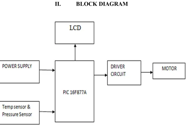
[image:3.612.166.464.92.297.2]II. BLOCK DIAGRAM
Fig. 1 Overall block diagram Unit
A. Working Principle
The speed of DC motor is straightforwardly proportional to the supply voltage. Pulse duration is straight forwardly proportional to the consequence of input voltage. When the value of voltage is near to the ground, pulse will engender constricted and the value of voltage is high, pulse width will engender wide. A modern adjustable speed AC machine system is prepared with an adjustable frequency drive that is a power electronic device for speed control of an electric machine. PWM controls fine-tune the duty ratio of the DC motor. When the temperature and pressure decreases of motor speed also decrease, when the temperature and pressure increases, the speed also increases. The average DC value of the signal can be varied by varying the duty cycle. The Varying speed will be displayed in the LCD. Same as the pressure and temperature values also displayed in the LCD.
B. Standard used for motor speed control using PWM
The speed of the DC motor can be personalized by varying the DC voltage across the two terminals of the motor. However if we acquire a DC motor and switch on the DC supply diagonally it, the motor takes a few time to speed up. This is for the reason that the motor has an inductive coil so it does not act in response straight away to the applied voltage. If the user switches the power off earlier than the motor reaches full speed, the motor starts to slow down. If the user switch the power on and off hurriedly enough the motor and hence the motor run at some speed between the zero and full speed. This is what achieved through the PWM signal. The motor speed can be modified with the dissimilarity in the duty cycle of the PWM signal.
C. Process of motor speed control using a power MOSFET
To control the speed of the DC motor by resources of the PWM signal, the user need to use a switch which can be switched on and off at PWM frequency and therefore control the supply voltage transversely the motor. This switch can be completed by using a high switching speed power MOSFET. The exploit of switch is to connect and disconnect the power transversely the motor at PWM frequency. A full duty cycle PWM pulse gives positive crest voltage while a zero duty cycle PWM pulse gives negative peak voltage.
III. PIC MICROCONTROLLER
originally urbanized by universal Instrument's Microelectronics separation. The name PIC initially referred to "Peripheral Interface Controller". PICs are accepted with developers and hobbyists alike due to their low cost, wide availability, huge user base, extensive assortment of application notes, availability of low cost or at no cost development tools, and sequential programming (and re-programming with flash memory) competence.
IV. TEMPERATURE SENSOR
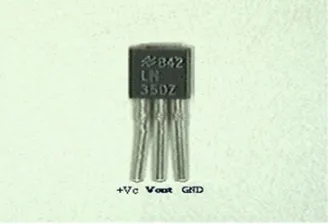
[image:4.612.226.390.247.359.2]The LM35 sequence are exactitude integrated-circuit temperature sensors, with an output voltage linearly proportional to the Centigrade temperature. Thus the LM35 has an enhancement over linear temperature sensors calibrated in ° Kelvin, as the user is not obligatory to subtract a large constant voltage from the output to obtain well-situated Centigrade scaling. The LM35 does not require any peripheral calibration or trimming to provide typical accuracies of ±¼°C at room temperature and ±¾°C over a full −55°C to +150°C temperature range. Low cost is guaranteed by trimming and calibration at the wafer plane. The low output impedance, linear yield, and precise inherent calibration of the LM35 make interfacing to readout or control circuitry especially easy. The device is used with single power provisions, or in the company of possitive and negative supplies. As the LM35 draws only 60 μA starting the supply, it has very low self-heating of less than 0.1°C in still air.
Fig. 2 LM-35 Temperature Sensor
V. PRESSURE SENSOR
The MPXV5050V series sensor integrates on-chip, bipolar op amp circuitry and skinny film resistor networks to make available a high output signal and temperature reimbursement. The MPXV5050V series piezoresistive transducer is a state-of-the-art, monolithic, signal accustomed, silicon pressure sensor. This sensor combines advanced micromachining techniques, emaciated film metallization, and bipolar semiconductor processing to make available an accurate, high level analog output signal that is proportional to applied pressure.
VI. POWER SUPPLY
The ac voltage, typically 220V RMS, is connected to a transformer, which steps that ac voltage down to the level of the desired dc output. A diode rectifier then provides a full-wave rectified voltage that is initially filtered by a simple capacitor filter to produce a dc voltage. This resulting dc voltage usually has some ripple or ac voltage variation. A regulator circuit removes the ripples and also remains the same dc value even if the input dc voltage varies, or the load connected to the output dc voltage changes. This voltage regulation is usually obtained using one of the popular the popular voltage regulator IC units.
Fig. 3 Power Supply Block Diagram
VII. DC MOTOR
[image:4.612.109.529.582.623.2]199
current operation through it generates an electromagnetic field associated with the center of the coil. As a result of switching the current on or off in a coil its magnetic field can be switched on or off or by switching the direction of the current in the coil the direction of the generated magnetic field can be switched 180°.
VIII. EXPERIMENTAL RESULTS
Proteus is the greatest simulation software for an assortment of designs with microcontroller. It is mainly well-liked because of availability of approximately all microcontrollers in it. So it is a versatile tool to test programs and embedded designs for electronics hobbyist. The user can simulate their programming of microcontroller in Proteus Simulation Software. After Simulation the circuit in Proteus Software can in a straight line make PCB design with it, so it could be all in one package for students and hobbyists. The speed of DC motor is in a straight line proportional to the supply voltage. Pulse duration is directly proportional to the value of input voltage. When the value of voltage is deliberate, pulse will generate narrow and the value of voltage is high, pulse will generate wide. A PWM control adjusts the duty ratio of the DC motor. DC voltage is converted to a square-wave signal. When the voltage of the motor decreases, then the speed must be decrease. When the voltage of the motor increase, the speed must increase. The average DC value of the signal can be wide-ranging by varying the duty cycle. LM35 is a precision temperature sensor and pressure sensors with these sensor outputs are proportional to the temperature (in ºC). Processed to display the corresponding temperature and pressure value on the LCD. The output voltage varies by means of 10 mV in response to every ºC rise/fall in temperature.
Fig.4. Simulation result
microcontroller used in this system has inherent PWM module which is used to control speed of the motor by varying the duty cycle. According to the readings commencing the temperature and pressure sensors duty cycle is varied without human intervention thus controlling motor speed can be achieved.
Fig.5 Practical result of temperature and pressure sensing unit
IX. CONCLUSION
Modern developments in science and technology make available a wide range scope of applications of high performance DC motor drives in neighborhood such as rolling mill, chemical progression, electric trains, robotic manipulators and the home electric appliances require speed controllers to carry out responsibilities. DC motors have speed control capabilities, which earnings that speed, torque and even direction of rotation can be changed at anytime to congregate new circumstance.The target of this project is to intend a DC motor speed control system by using microcontroller PIC16F877A. The controller will preserve the speed by the side of most wanted speed when there is a discrepancy of load. By varying the PWM signal from microcontroller to the motor driver, motor speed can be controlled back to preferred value easily. The authentic temperature, pressure and set value of temperature, pressure were getting displayed on the LCD screen. The speed of motor depends on the temperature and pressure hence there is no need for regulating the speed physically. Output was verified by setting the temperature at dissimilar places and it was found at room temperature and weather temperature.
REFERENCES
[1] Dong Jiang, Member, IEEE, Fei Wang, Fellow, IEEE, and Jing Xue, Student Member, IEEE ” PWM Impact on CM Noise and AC CM Choke for Variable-Speed Motor Drives” IEEE TRANSACTIONS ON INDUSTRY APPLICATIONS, VOL. 49, NO. 2, MARCH/APRIL 2013
[2] Da Zhang, Student Member, IEEE, Hui Li, Senior Member, IEEE, and Emmanuel G. Collins, Senior Member, IEEE “Digital Anti-Windup PI Controllers for Variable-Speed Motor Drives Using FPGA and Stochastic Theory” IEEE TRANSACTIONS ON POWER ELECTRONICS, VOL. 21, NO. 5, SEPTEMBER 2006
[3] K. Iizuka, H. Uzuhashi, M. Kano, T. Endo, and K. Mohri, “Microcomputer control for sensor less brushless motor,” IEEE Trans. Ind.Applicat., vol. IA-21, pp. 595–601, May/June 1985.
[4] Fernando J. T. E. Ferreira, Senior Member, IEEE, João A. C. Fong, and Anibal T. de Almeida, Senior Member, IEEE “Ecoanalysis of Variable-Speed Drives for Flow Regulation in Pumping Systems” IEEE TRANSACTIONS ON INDUSTRIAL ELECTRONICS, VOL. 58, NO. 6, JUNE 2011
[5] Jaehyuck Kim, Student Member, IEEE, Keunsoo Ha, Member, IEEE, and R. Krishnan, Fellow, IEEE” Single-Controllable-Switch-Based Switched Reluctance Motor Drive for Low Cost, Variable-Speed Applications” IEEE TRANSACTIONS ON POWER ELECTRONICS, VOL. 27, NO. 1, JANUARY 2012
[6] Norman S. Nise. “Control Systems Engineering”. 2nd
Edition. Redwood City, California: The Benjamin/Cummings Publishing Company, Inc. 1995. [7] Ms. Ei Ei Thaw *, Mr. Zaw Min Min Htun**”Design and Implementation of Motor Speed control and Temperature sensing unit using PIC Controller”
International Journal of Scientific Research Engineering & Technology (IJSRET), ISSN 2278 – 0882 Volume 3 Issue 2, May 2014.
[8] B.K. Lee and M. Ehsani, “Advanced Simulation Model for Brushless DC Motor Drives, “Electric Power Components and Systems 31,841–868, 2003 [9] J Bozo Terzic and Martin Jadric, “Design and Implementation of the Extended Kalman Filter for the Speed and Rotor Position Estimation of Brushless