International Journal of Emerging Technology and Advanced Engineering
Website: www.ijetae.com (ISSN 2250-2459, ISO 9001:2008 Certified Journal, Volume 7, Issue 10, October 2017)
60
Modelling and Simulation of Asynchronous Generator Wind
Turbine for Different Wind Speed
Deepak Bohra
1, M. K. Bhaskar
2, Dharmendra Jain
3, Manish parihar
41,4PG Scholar, 2Professor, 3PhD Scholar, Dept. of EE, M.B.M. Engineering College, JNV University, Jodhpur, Rajasthan, India Abstract— This paper present the modelling and simulation
of the Asynchronous generator wind turbine. The asynchronous generator wind turbine model consists of wind turbine profiles which attribute to the mechanical power and torque characteristics of wind turbine. The Asynchronous generator wind turbine model (AGWT-Model) has been representing the wind turbine simulation results using a MATLAB/SIMULIK. The AGWT-Model can work as induction generator. The wind turbine simulation model can display mechanical power, torque, current, voltage and power characteristics and their values changes according to the wind velocity. The torque from the wind turbine simulator can be used to drive the asynchronous generator to generate the power fed into the load. The AGWT-Model was further tested upon step changes in the wind velocity as well as the blade pitch angle, confirming the need of power control.
Keywords— Wind energy, AGWT-Model, wind turbine
simulator, pitch angle, induction generator, Wind velocity, Turbine power, Power coefficient, Tip speed ratio, Generator, Grid.
I. INTRODUCTION
Wind energy is one of the fastest growing renewable energies in the world. Wind as a source of power is very attractive because it is plentiful, inexhaustible, renewable and non-polluting. In recent years, due to decreases in fossil fuels, the energy shortage and environment pollution has affected the lives of the humans and social development. Conventional energy such as coal, oil and gas will be used out in a few years and will cause serious environmental problems. So the renewable energy, especially wind energy and solar energy have become more considerable all over the world [1]. A wind turbine is a rotary device that extracts energy from the wind and converts into rotary mechanical energy. Conventional wind energy is divided into three components. The first is the rotor which consists of two or three fiber glass blades joined to a hub that contains hydraulic motors that change each blade according to prevailing wind conditions so that the turbine can operate efficiently at varying wind speeds. The nacelle sits atop the tower and holds all the turbine machinery. Because it must be able to rotate to follow the wind direction, it is connected to the tower via bearings.
The nacelle is the housing that protects the main frame and the components attached to it. The structural tower supports the rotor and the nacelle. The kinetic energy in the wind is converted into mechanical energy by the turbine shaft and gearbox arrangement because of the different operating speed ranges of the wind turbine rotor and generator. The generator converts this mechanical energy into electrical energy. The mechanical power obtained can be used to perform important tasks such as grinding of grain or pumping of water. The electricity generated can be used in daily life activities such as power homes, schools, hospital, industries, businesses etc [4].
Nowadays, modelling is the basic tool for analysis, such as optimization, project, design and control [1, 2, 9, and 10]. The main wind turbine generators can be grouped into 2 classes: variable speed wind turbine and fixed speed wind turbine. The main difference is the electrical system where variable–speed wind turbine is more complicated than fixed-speed wind turbine. The fixed-speed wind turbine has
the advantage of being simple, robust and reliableand well
proven. And the cost of its electrical parts is low. The aim of this work this paper presents equivalent model of the wind generator system with fixed speed wind turbine connected to grid [5].
II. TURBINE MODEL
International Journal of Emerging Technology and Advanced Engineering
Website: www.ijetae.com (ISSN 2250-2459, ISO 9001:2008 Certified Journal, Volume 7, Issue 10, October 2017)
61
Wind turbines operate in two modes namely constant or variable speed. For a constant speed turbine, the rotor turns at constant angular speed regardless of wind variations. One advantage of this mode is that it eliminates expensive power electronics such as inverters and converters. Its disadvantage however, is that it constrains rotor speed so that the turbine cannot operate at its peak efficiency in all wind speeds. For this reason a constant wind speed turbine produces less energy at low wind speeds than does a variable wind speed turbine which is designed to operate at a rotor speed proportional to the wind speed below its rated wind speed. The output power or torque of a wind turbine is determined by several factors. Among them are (i) turbine speed, (ii) rotor blade tilt, (iii) rotor blade pitch angle (iv) size and shape of turbine, (v) area of turbine, (vi) rotor geometry whether it is a HAWT or a VAWT, (vii) and wind speed. A relationship between the output power and the various variables constitute the mathematical model of the wind turbine. A mathematical model of wind turbine is essential in the understanding of the behaviour of the wind turbine over its region of operation and also modelling enables control of wind turbines [4].
III. MATHEMATICAL FORMULATION OF TURBINE MODEL
According to Newton’s second law of motion, an object having mass m, velocity v, acceleration a, is displaced from rest to distance s, under force F:
E = W = Fs
F = ma ………. (1)
Thus, the kinetic energy KE becomes
KE = m a s ………. (2)
Assuming the initial velocity of the object is zero, we
have that a = v2/2s. Hence from equation (2) we have that
………. (3)
This kinetic energy formulation is based on the fact that the mass of the solid is a constant. However, if we consider wind (air in motion) as a fluid, both density and velocity can change and hence no constant mass. For this reason formulate the kinetic energy law with a factor of 2/3 instead of 1/2.
The power P in the wind is given by the rate of change of kinetic energy, i.e.
…
……. (4)But mass flow rate dm/dt is given by dm/dt = ρAv where A is the area through which the wind in this case is flowing and ρ is the density of air. With this expression, equation (4) becomes
………. (5)
The actual mechanical power Pw extracted by the rotor
blades in watts is the difference between the upstream and the downstream wind powers, i.e.
Pw = ρ A v(v2u – v2d) ………. (6)
Where vu is the upstream wind velocity at the entrance of the rotor blades in m/s and vd is the downstream wind velocity at the exit of the rotor blades in m/s. We shall see later that these two velocities give rise to the blade tip speed ratio. Now from the mass flow rate, we may write
ρ A v = ………. (7)
v, being the average of the velocities at the entry and exit of rotor blades of turbine. With this expression, equation (6) becomes
Pw = 1/2ρA (v2u – v2d) (vu+vd)/2
This may be simplified as follows:
Pw = [ρ A { (v2u− v2d) + (v2u− v2d)}]
= [ρ A { }]
= ]
Or ………. (8)
Where Cp =
International Journal of Emerging Technology and Advanced Engineering
Website: www.ijetae.com (ISSN 2250-2459, ISO 9001:2008 Certified Journal, Volume 7, Issue 10, October 2017)
62
The expression for Cpin equation (9) is the fraction of upstream wind power captured by the rotor blades, is often called the Betz limit after the German physicist Albert Betz
who worked it out in 1919. Cp is also known as the power
coefficient of the rotor or rotor efficiency. The power coefficient is not a static value. It varies with tip speed ratio of the wind turbine.
The ratio of the blade tip speed of rotor to the speed of the wind is called tip speed ratio, λ, given by
λ = ……….. (10)
Or λ = ………. (11)
The blade tip speed in meters per second can be calculated from the rotational speed of the turbine and the length of the blades used in the turbine, i.e.
Blade tip speed = …. (12)
Where R is the radius of the turbine and ω is measured
in radian per second.
Substitution of equation (11) into equation (9), we get
Cp= (1 + λ) (1 − λ2)/2 ………. (13) Differentiate Cp with respect to λ and equate to zero to
find value of λ that makes Cp a maximum, i.e.
Resulting λ = −1 or λ = 1/3. Now λ = 1/3 makes the
value of Cp a maximum. This maximum value is 16/27.
Thus the Betz limit says that no wind turbine can convert more than 16/27 (59.3%) of the kinetic energy of the wind into mechanical energy turning a rotor, i.e. Cpmax = 0.59. The power coefficient for an ideal with turbine is 0.59; it has been found that its more practical value is about 0.45. Further the generator also has some losses and the overall power coefficient is about 0.35. The real world is well below the Betz limit with values of 0.35 − 0.45 common even in best designed wind turbines.
Higher the value of λ gives the better efficiency of the generator.
There are disadvantages however. High λ causes erosion
of leading edges of the blades due to impact of dust or sand particles found in the air.
This would require use of special erosion resistant coating material that may increase the cost of energy.
Higher λ also leads to noise generation, vibration; reduced
rotor efficiency due to drag and tip losses and excessive rotor speeds can lead to turbine failure.
Other factors that impede complete energy conversion in a complete turbine system are things such as gearbox, bearings, number and shape of blades etc. Only 10− 30% of the power of the wind is ever actually converted into usable electricity.
ρ is a function of both air pressure and temperature.
When air pressure increases ρ increases. When air
temperature decreases ρ increases. This is in accordance
with the equation of state
P = ρ R T ………. (14)
Where, R is the gas constant. Both temperature and pressure decrease with increasing elevation. Hence site location is important as elevation has major effect on power generated as a result of air density variation. At atmospheric pressure, Patm = 14.7psi, temperature is T =
60ºF and density is ρ = 1.225kg/m3. Temperature and
pressure both vary with elevation. This affects the air density. Propose the following relation
ρ = ρ0 Hm ………. (15)
Where Hmis site elevation in meters. At high elevations
the air density corrections can be important [4].
IV. POWER COEFFICIENT ANALYSIS
The parameters which are shown in above equation are required in power production in case of wind turbine. The
power coefficient Cpis a non-linear function. It is the most
important parameter in the case of power regulation. It value is unique to each turbine type and is a function of wind speed that the turbine is operating in. Each turbine manufacturer provides look up tables for Cp for operation purposes. Other than look up tables from turbine manufactures, models for power coefficient have been
developed. For example models Cpas a function of the tip
speed ratio and the blade pitch angle θ in degrees as
International Journal of Emerging Technology and Advanced Engineering
Website: www.ijetae.com (ISSN 2250-2459, ISO 9001:2008 Certified Journal, Volume 7, Issue 10, October 2017)
63
Where the values of the coefficients C1−C6 and x depend
on turbine type. θ is defined as the angle between the plane of rotation and the blade cross section chord.
For a particular turbine type C1 = 0.5, C2 = 116, C3 = 0.4, C4 = 0, C5 = 5, C6 = 21 and β is defined by
1/β = ………. (17)
The following relation for Cp
Cp= …. (18)
Where θ is the pitch angle of the blade in degrees, λ is the tip speed ratio of the turbine defined by λ = v(mph)/ωb(rads−1) where ωb is the turbine angular speed [4].
V. MODELING AND CONTROL OF THE POWER OUTPUT
The power output of a turbine is determined by the area of the rotor blades, wind speed and the power coefficient. The output power of the turbine can be varied by changing the area and flow conditions at the rotor system and this forms the basis of the control system. Cpis achieved at a particular λ which is specific to the design of the turbine.
Hence the model turbine consists of equations (5), power in the wind, equation (8), power captured by the turbine, equation (10), tip speed ratio of the turbine and the power coefficient equation (16). Control output of wind energy lies in a number of parameters. The rotor area and flow conditions at the rotor system (v, ρ, Cp), the rotor torque and pitch angle control. Fixed speed stall-regulated turbines have no options for control input. However, variable speed wind turbines use generator torque to control and optimize power output. They also use pitch control to control the
output power above their rated wind speed [4].
VI. MODELING AND SIMULATION
The wind turbine is characterized by the non-dimensional curves of the power coefficient as a function of both tip speed ratio and the blade pitch angle. The tip speed ratio is the ratio of linear speed at the tip of blades to the speed of the wind [6].
[image:4.612.98.514.424.562.2]The input quantities of wind turbine are as follows: - Pitch angle (deg) = 0, Wind speed (m/s) = 10 m/s, Asynchronous Generator (Squirrel-cage rotor type) Nominal power = 4000 VA, Voltage (line to line) = 400 V, Frequency = 50 Hz.
Fig. 1 : Fixed speed wind turbine with induction generator [8]
[image:4.612.382.503.605.679.2]International Journal of Emerging Technology and Advanced Engineering
Website: www.ijetae.com (ISSN 2250-2459, ISO 9001:2008 Certified Journal, Volume 7, Issue 10, October 2017)
64
The model shown in Fig. 2 takes wind speed and pitch angle as input parameter and gives the mechanical torque to the generator. This asynchronous generator gives the torque, rotor speed, current, voltage, active power and reactive power.
[image:5.612.56.548.201.393.2]The simulation output for fixed pitch angle and different wind speed are shown in Fig. 4 to 6. When Pitch angle is 0 degree and wind speed is 1 meter per second (m/s) then simulation output is shown in Fig 4.
Fig. 4 : AGWT-Model Output ( pitch angle = 0 degree and Wind Speed = 1 m/s )
When Pitch angle is 0 degree and wind speed is 5 meter per second (m/s) then simulation output is shown in Fig 5.
[image:5.612.62.553.420.637.2]International Journal of Emerging Technology and Advanced Engineering
Website: www.ijetae.com (ISSN 2250-2459, ISO 9001:2008 Certified Journal, Volume 7, Issue 10, October 2017)
65
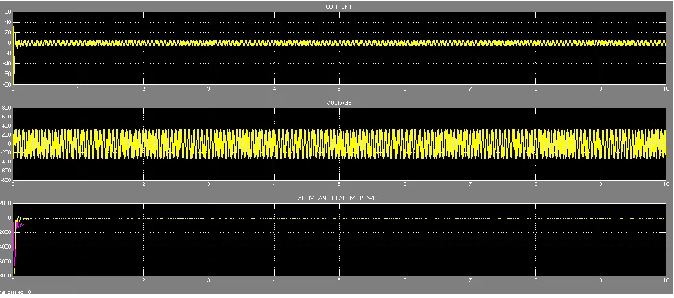
[image:6.612.67.543.156.356.2]When Pitch angle is 0 degree and wind speed is 10 meter per second (m/s) then simulation output is shown in Fig 6.
Fig. 6 : AGWT-Model Output ( pitch angle = 0 degree and Wind Speed = 10 m/s )
VII. SIMULATION RESULTS FOR ASYNCHRONOUS
GENERATOR WIND TURBINE
[image:6.612.39.302.500.721.2]Study is done by keeping following parameters as Fixed parameters = pitch angle in degree, Variable parameter = Wind speed in meter per second (m/s). The value of power for asynchronous generator wind turbine model is shown in below tables.
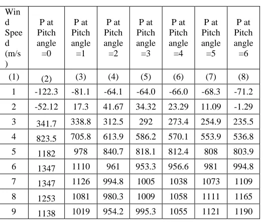
TABLE-I
SIMULATION RESULTS OF GENERATED POWER (P) IN WATTS FOR AGWT-MODEL
Win d Spee d (m/s )
P at Pitch angle =0
P at Pitch angle =1
P at Pitch angle =2
P at Pitch angle =3
P at Pitch angle =4
P at Pitch angle =5
P at Pitch angle =6
(1) (2) (3) (4) (5) (6) (7) (8)
1 -122.3 -81.1 -64.1 -64.0 -66.0 -68.3 -71.2
2 -52.12 17.3 41.67 34.32 23.29 11.09 -1.29
3 341.7 338.8 312.5 292 273.4 254.9 235.5
4 823.5 705.8 613.9 586.2 570.1 553.9 536.8
5 1182 978 840.7 818.1 812.4 808 803.9
6 1347 1110 961 953.3 956.6 981 994.8
7 1347 1126 994.8 1005 1038 1073 1109
8 1253 1081 980.3 1009 1058 1111 1165
9 1138 1019 954.2 995.3 1055 1121 1190
10 1049 978.7 942.9 989.7 1054 1127 1204
11 1009 972.9 957.8 1006 1070 1143 1224
12 1020 1006 1004 1049 1109 1180 1260
13 1077 1075 1080 1121 1175 1240 1316
14 1171 1175 1184 1218 1265 1324 1394
15 1294 1299 1309 1338 1378 1429 1493
16 1439 1446 1455 1478 1512 1556 1613
17 1603 1608 1616 1635 1663 1701 1751
18 1780 1785 1792 1807 1830 1862 1906
19 1971 1974 1980 1992 2010 2038 2076
20 2172 2175 2179 2188 2204 2226 2259
21 2382 2385 2388 2395 2407 2427 2455
22 2601 2603 2605 2611 2621 2637 2661
23 2828 2829 2831 2835 2843 2857 2878
24 3062 3062 3064 3068 3074 3086 3103
25 3302 3303 3304 3306 3311 3322 3336
International Journal of Emerging Technology and Advanced Engineering
Website: www.ijetae.com (ISSN 2250-2459, ISO 9001:2008 Certified Journal, Volume 7, Issue 10, October 2017)
66
To achieve the results as shown in the colomn-2 by measuring the generated power by keeping pitch angle zero-degree as a fixed parameter and vary the wind speed from 1 m/s to 25 m/s, in steps 1 m/s as an increment. The maximum power 3302 Watts is achieved at fixed pitch angle zero-degree, wind speed is 25 m/s. Similarly to achieve the results as shown in the colomn-3 by measuring the generated power by keeping pitch angle one-degree as a fixed parameter and vary the wind speed from 1 m/s to 25 m/s, in steps 1 m/s as an increment. The maximum power 3303 Watts is achieved at fixed pitch angle one-degree, wind speed is 25 m/s. Now to achieve the results as shown in the colomn-3 to 8 by varying pitch angle and wind speed.
VIII. CONCLUSION
This paper has presented the simulation of
Asynchronous generator wind turbine model (AGWT-Model) by using a MATLAB/Simulink. Variable values of power are obtained for fixed pitch angle and different wind speed. This paper gives the brief description of the output characteristics of wind turbine as well as asynchronous generator. Also describes the effect of changes the value of wind speeds and pitch angle on output characteristics. This AGWT-Model is designed to give maximum power at different values of pitch angle and wind speed.
REFERENCES
[1] Phlearn Jansuya and Yuttana Kumsuwan, “Design of MATLAB/Simulink Modeling of Fixed-Pitch Angle Wind Turbine Simulator”, Sciversa ScienceDirect, Energy Procedia , August, 2013.
[2] Jasmin Martinez, “Modeling and Control of Wind Turbines”, Department of Chemical Engineering and Chemical Technology, Imperial College, London, September 21, 2007.
[3] A. Honrubia-Escribano, F. Jiménez-Buendía, A. Molina- García, J.A. Fuentes-Moreno, E. Muljadi, and E. Gómez- Lázaro, “Analysis of Wind Turbine Simulation Models: Assessment of Simplified versus Complete Methodologies”, ISEF 2015 – XVII International Symposium on Electromagnetic Fields in Mechatronics, Electrical and Electronic Engineering Valencia, Spain, September 2015.
[4] A. W. Manyonge, R. M. Ochieng, F. N. Onyango, and J. M. Shichikha,“Mathematical Modelling of Wind Turbine in a Wind Energy Conversion System: Power Coefficient Analysis”, Applied Mathematical Sciences,Vol.6,June 2012.
[5] D.johra Saheb-Koussa, Mourad Haddadi , Maiouf Belhamel, Mustapha koussa &Said noureddine, “Modeling and simulation of windgenerator with fixed speed wind turbine under Matlab-Simulink”, Sciversa ScienceDirect, Energy Procedia 18, November 2012.
[6] Harish Kumar Khayani, Pankaj Vaishnav, Piyush Rai, Praful Bohra, “Modeling and Simulation of Wind Turbine under the Condition Prevailing in and around Jodhpur District”, National Conference on Innovations and Recent Trends in Engineering and Technology, September 2014.
[7] Kuldipsinh. I. Rathod, Mahipalsinh.B.Jhala & A.D.Patel, “Modeling and Simulation of Wind Turbine Connected to Pmsg for Wind Mill Application”, International Global Journal for Research Analysis, Volume : 3 | Issue: 3 | March 2014. [8] Mujaddin Morshed Chowdhury, “Modelling and Control of Direct
Drive Variable Speed Wind Turbine with Interior Permanent Magnet Synchronous Generator”, PhD Thesis, University of Tasmania, June 2014.
[9] Makbul Anwari, “Modeling and Simulation of Grid- Connected PV/Wind Power System”, Jordan International Energy Conference, Amman 2011.
[10] Dharmendra Jain, M.K. Bhaskar, Shyam K. Joshi, Deepak Bohra, “ Analysis of Load Frequency Control Problem for Interconnected Power System Using PID Controller”, IJETAE, issn 2250-2459, iso 9001: 2008Certified Journal, Volume 4, Issue 11, November 2014. [11] Dharmendra Jain, M.K. Bhaskar, Manoj Kumar, “Comparative
![Fig. 1 : Fixed speed wind turbine with induction generator [8]](https://thumb-us.123doks.com/thumbv2/123dok_us/8682238.874988/4.612.382.503.605.679/fig-fixed-speed-wind-turbine-induction-generator.webp)