Modeling and Study of a Standalone PMSG Wind
Generation System Using MATLAB/SIMULINK
Mohammed Aslam Husain
*, Abu Tariq
Department of Electrical Engineering, Aligarh Muslim University (AMU), Aligarh, India *Corresponding Author: [email protected]
Copyright © 2014Horizon Research Publishing All rights reserved
Abstract
The paper presents the modeling and performance analysis of a standalone wind system in MATLAB/SIMULINK environment. Stand-alone systems using renewable energy sources, such as wind energy with storage battery banks are commonly used to supply remote houses. The model of wind turbine is developed using basic circuit equations governing the operation of the wind turbine. Permanent Magnet Synchronous Generator (PMSG), which is based on variable-speed operation, has been used in this paper. Since the speed of wind turbine is variable, the generator is controlled by power electronic devices. A rectifier is used to rectify the output voltage of PMSG and DC/DC buck converter is used to decrease this rectified voltage to that of battery and connected DC load. The buck converter is controlled to extract the maximum power output of wind system. Firstly the mathematical modeling of a wind turbine is done and its different characteristics have been obtained for different parameters. Secondly a standalone model of wind system is modeled and analyzed. This paper is useful to model, simulate and study the effect of change in wind speed of a standalone wind system.Keywords
Turbine, PMSG, Wind Speed, MATLAB Simulation1. Introduction
Standalone Wind generation system offers a feasible solution to distributed power generation for isolated localities where utility grids are not available. It is also free from pollution what makes it more attractive. For isolated localities, one practical approach to self-sufficient power generation involves using a wind turbine with battery storage to create a stand-alone system [1, 2].
The common types of AC generator that are possible candidates in modern wind turbine systems are as follows: Squirrel-Cage rotor Induction Generator; Wound-Rotor Induction Generator; Doubly-Fed Induction Generator; Synchronous Generator (With external field excitation); and
Permanent Magnet Synchronous Generator [3]. However, in this paper the variable-speed directly-driven multi-pole permanent magnet synchronous generator (PMSG) wind architecture is chosen for this purpose, it offers better performance due to higher efficiency and less maintenance because it does not have rotor current. PMSG can be used without a gearbox, which implies a reduction of the weight of the nacelle and reduction of costs [1].
The main task of this paper is to develop a simulation model of a standalone PMSG Wind generation System using MATLAB/SIMULINK system. Characteristics of modeled wind turbine and standalone wind system have been shown for different conditions. This paper includes in details the equations that form the wind turbine. The aim of this paper is to provide the reader with all necessary information to develop wind turbine models and circuits that can be used in the simulation for a standalone wind generation system.
2. Modeling of Wind Turbine
Present The power captured from the wind turbine is given bythe equation (1) [1,2,9].
Pw=1/2 Cp ρAVw3 (1)
Where Cpis the power coefficient, ρ is the air density,
which is equal to 1.225 kg/m3, V
wis the wind speed in m/s
and A is the area swept by the rotor in m2.
The volume of aerodynamic torque Tw in N-m is given by
the ratio between the power from the wind and the turbine rotor speed ww in rad/s, as follows
Tw = Pw/ ww (2)
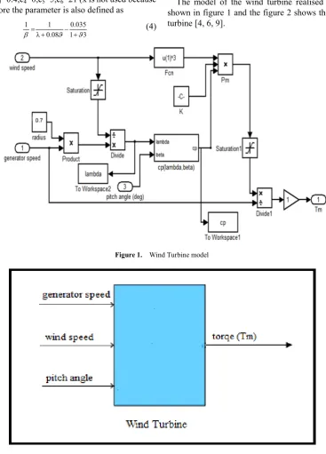
Figure 1. Wind Turbine model
Figure 2. Mask of Wind Turbine
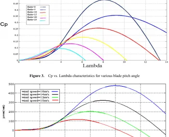
Figure 3. Cp vs. Lambda characteristics for various blade pitch angle
Figure 4. Power vs. speed curves for different wind speeds
Figure 5. Torque vs. speed curves for different wind speeds
[image:3.595.150.465.416.586.2]excitation system can be eliminated, decreasing again weight, losses, costs and maintenance requirements. The efficiency of a PMSG wind turbine is thus assessed to be higher than for other concepts. However, the disadvantages of the permanent magnet excitation are the still high costs for permanent magnet materials and a fixed excitation, which cannot be varied according to the working condition requirement. As multi-pole permanent magnet generators are low speed applications and generally connected to the grid using a frequency converter system, the generator has no damper winding in the rotor core. Moreover, due to the permanent excitation a PMSG has no field windings, in which transient currents could be induced or damped respectively.
Hence, in case of load changes the field windings would not contribute to damping either. As neither a damper nor field winding exists in a PMSG, no transient or sub-transient reactance can be defined for the PMSG.
i.e.
Xd=Xd' =Xd''
Xq=Xq' =Xq''
where
XdandXq -synchronous reactance
Xd' and Xq' -transient reactance
Xd'' and Xq'' -sub-transient reactance
Nevertheless, as the multi-pole PMSG is used at low speed application with slow dynamics, a damper winding is not as much important. However, damping of the system must then be applied by the use of converter control[7,8, 9].
4. Building the Mathematical Model and
Circuit of Wind System with Buck
Converter Connected To a Battery
and a Load
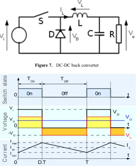
DC-DC converter is used to buck the rectified voltage. In the converter circuit the gate receives the pulse from PWM generator. Figure 7 depicts a step-down or a PWM buck converter. It consists of dc input voltage source Vi, boost
inductor L, controlled switch S, diode D, filter capacitor C, and load resistance R [5].
Figure 8. Evolution of the voltages and currents with time in an ideal buck converter operating in continuous mode
A buck converter operates in continuous mode if the current through the inductor (IL) never falls to zero during the
commutation cycle. In this mode, the operating principle is described by the plots in figure 2.17:
When the switch pictured above is closed, the voltage across the inductor is . The current through the inductor rises linearly. As the diode is reverse-biased by the voltage source V, no current flows through it;
When the switch is opened, the diode is forward biased. The voltage across the inductor is
(neglecting diode drop). Current IL decreases.
The overall Simulink model is shown in Figure 9. A 480W, 34 pole, 300 rpm rated speed, permanent-magnet synchronous generator(PMSG), a diode rectifier and a (DC/DC) buck converter for the tracking of the maximum power point is used in this model. Lead acid battery used here has a nominal voltage rating of 48V [4, 5].
5. Simulation Results
[image:4.595.315.553.80.369.2]Figure 9. Simulation model of standalone wind system
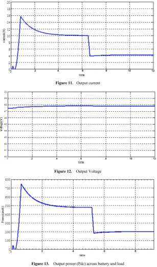
[image:5.595.75.544.317.745.2]Figure 11. Output current
Figure 12. Output Voltage
Figure 13. Output power (Pdc) across battery and load
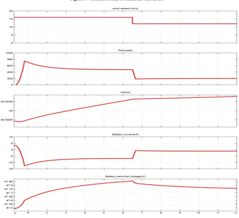
[image:6.595.152.460.77.599.2]In Figure 10, at time t1=3sec the system reaches its maximum output power and between t1 to t2(=6.5sec) the output power
is 479.8watts equal to the maximum power (as shown in Figure 4) of the wind system at a wind speed of 16m/s.
As the wind speed changes the corresponding value of the output power gets changed. At t2(=6.5sec) the wind speed
changes from 16 to 12m/s and the corresponding value of the output power changes from 479.8 to 202.5watts.
These values are the maximum value of power corresponding to wind speed of 16 and 12m/s respectively. Initially till the output power reaches its maximum value, the battery was feeding the load. But after that, the wind system starts charging the battery and feeds the load.
Also as the value of wind speed decreases to 12m/s, the rate of charging reduces as it is clear from the change in value of battery current from 5amperes to less than 1amperes.
Figures 11 to 14 show the waveforms of output current, output voltage, output power of the wind system and output voltage of the wind generator respectively for step change in wind speed from 16 to 12m/s.
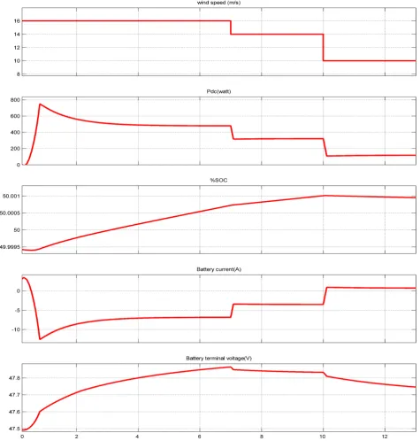
Figure 15 shows different characteristics of the simulated wind system for step change in wind speed from 16m/s to 14m/sand then to 10m/s.
[image:7.595.72.548.236.735.2]system or hybrid systems.
REFERENCES
[1] Alejandro Rolan, AlvaroLuna, Gerardo Vazquez, Daniel Aguilar, Gustavo Azevedo, “Modeling of a Variable Speed Wind Turbine with a Permanent Magnet Synchronous Generator ”. IEEE International Symposium on Industrial Electronics (ISlE 2009) Seoul Olympic Parktel, Seoul, Korea July 5-8, 2009.
[2] Polinder H., de Haan S. W. H., Dubois M. R., Slootweg J., ”Basic Operation Principles and Electrical Conversion Systems of Wind Turbines”, NORPIE / 2004, Nordic
Experimental investigation”, Energy 35 (2010) 2587-2595. [6] Akhmatov V., “Variable-Speed Wind Turbines with
Doubly-Fed Induction Generators Part III: Model with the Back-to-back Converters”, Wind Engineering, Volume 27, No. 2, pp 79-91, 2003
[7] Hansen A.D., Michalke G., “Modelling and control of variable speed multipole PMSG wind turbine”, submitted to Wind Energy, 2007.
[8] Hong-Woo Kima, Sung-SooKimb, Hee-Sang Koa,
“Modeling and control of PMSG-based variable-speed wind turbine”, Electric Power Systems Research 80 (2010) 46–52. [9] Mohammed Aslam Husain and Abu Tariq, “Modeling of a